EP0103094B1 - Manchon d'accouplement pour la jonction à un outil de travail présentant un raccord à accouplement rapide - Google Patents
Manchon d'accouplement pour la jonction à un outil de travail présentant un raccord à accouplement rapide Download PDFInfo
- Publication number
- EP0103094B1 EP0103094B1 EP83106635A EP83106635A EP0103094B1 EP 0103094 B1 EP0103094 B1 EP 0103094B1 EP 83106635 A EP83106635 A EP 83106635A EP 83106635 A EP83106635 A EP 83106635A EP 0103094 B1 EP0103094 B1 EP 0103094B1
- Authority
- EP
- European Patent Office
- Prior art keywords
- coupling
- nipple
- coupling sleeve
- locking member
- sleeve
- Prior art date
- Legal status (The legal status is an assumption and is not a legal conclusion. Google has not performed a legal analysis and makes no representation as to the accuracy of the status listed.)
- Expired
Links
Images
Classifications
-
- B—PERFORMING OPERATIONS; TRANSPORTING
- B25—HAND TOOLS; PORTABLE POWER-DRIVEN TOOLS; MANIPULATORS
- B25F—COMBINATION OR MULTI-PURPOSE TOOLS NOT OTHERWISE PROVIDED FOR; DETAILS OR COMPONENTS OF PORTABLE POWER-DRIVEN TOOLS NOT PARTICULARLY RELATED TO THE OPERATIONS PERFORMED AND NOT OTHERWISE PROVIDED FOR
- B25F1/00—Combination or multi-purpose hand tools
- B25F1/02—Combination or multi-purpose hand tools with interchangeable or adjustable tool elements
-
- A—HUMAN NECESSITIES
- A01—AGRICULTURE; FORESTRY; ANIMAL HUSBANDRY; HUNTING; TRAPPING; FISHING
- A01B—SOIL WORKING IN AGRICULTURE OR FORESTRY; PARTS, DETAILS, OR ACCESSORIES OF AGRICULTURAL MACHINES OR IMPLEMENTS, IN GENERAL
- A01B1/00—Hand tools
- A01B1/22—Attaching the blades or the like to handles; Interchangeable or adjustable blades
- A01B1/222—Adjustable blades
-
- B—PERFORMING OPERATIONS; TRANSPORTING
- B25—HAND TOOLS; PORTABLE POWER-DRIVEN TOOLS; MANIPULATORS
- B25G—HANDLES FOR HAND IMPLEMENTS
- B25G3/00—Attaching handles to the implements
- B25G3/02—Socket, tang, or like fixings
- B25G3/12—Locking and securing devices
- B25G3/20—Locking and securing devices comprising clamping or contracting means acting concentrically on the handle or socket
-
- B—PERFORMING OPERATIONS; TRANSPORTING
- B25—HAND TOOLS; PORTABLE POWER-DRIVEN TOOLS; MANIPULATORS
- B25G—HANDLES FOR HAND IMPLEMENTS
- B25G3/00—Attaching handles to the implements
- B25G3/02—Socket, tang, or like fixings
- B25G3/12—Locking and securing devices
- B25G3/26—Locking and securing devices comprising nails, screws, bolts, or pins traversing or entering the socket
Definitions
- the invention relates to a coupling sleeve for connection to a tool having a quick coupling nipple, in particular gardening tool, in which the nipple preferably decreases in cross section towards its free end and is designed in cross section as a regular hexagon at least in the region of its free end, and wherein the coupling sleeve has a coupling section in which the coupling nipple can be fixed without play with the aid of a latching element and guides which engage on the circumference.
- the invention is therefore based on the object of providing a coupling sleeve which enables the use of a working tool equipped with a coupling nipple of the type described at the outset as a hand tool lying lightly in the hand.
- the coupling sleeve according to DE-A-2 617 621 is less suitable for this as a device handle.
- a coupling sleeve in which at least three substantially parallel and axially symmetrical guide ribs are provided on the inside of the coupling section, the flat tops of which are assigned to the surfaces of the hexagonal nipple end with little play and which extend over the longitudinal section extend the sleeve, which corresponds to the axial longitudinal extent of the hexagonal section of the nipple, and in which the latching element is arranged on the free end of the coupling sleeve on the implement side.
- a coupling sleeve designed in this way has the advantage, on the one hand, that it ensures a perfect coupling with the nipple of the implement and, on the other hand, forms a handle that is easy to hold and does not have a latching element that impairs its handling in its grip area.
- a coupling sleeve designed in this way is inexpensive to manufacture and, moreover, easy to assemble.
- the locking member of the coupling sleeve according to the invention is preferably designed so that it presses an essentially cylindrical portion of the coupling nipple for play-free mounting against the opposite wall of the coupling sleeve.
- the end of the coupling sleeve facing the implement can form a stop in the insertion direction with a shoulder of the coupling nipple, which in cooperation with the locking member prevents an axial displacement of the coupling nipple in the coupling sleeve after the coupling process has ended.
- the latching element can be inserted into recesses which are provided in the cylindrical section of the coupling nipple.
- recesses Preferably, six such recesses are evenly distributed around the circumference of the coupling nipple.
- These recesses and the effective end of the locking member are preferably conical or wedge-shaped, so that they form cooperating wedge surfaces for pressing the stop surfaces of the coupling sleeve and coupling nipple, with the advantage that when pressing the stop surfaces of the coupling sleeve and coupling nipple, wedging on both sides and axial securing occurs .
- the locking member is designed as a radially acting screw, the free end of which can preferably be hemispherical.
- the radial play of the six-surface section of the coupling nipple between the guide ribs is preferably less than that of the radial play of the cylindrical section of the coupling nipple, in which the sleeve end having the latching member and the six-surface nipple section between the guide ribs for canceling the radial play of the free coupling end by radial displacement of the cylindrical section can be clamped with the aid of the locking member.
- the coupling sleeve can have, at least in its end region facing the implement, axially extending grooves which, when the coupling nipple is fixed, serve to receive dirt particles which have previously entered the coupling sleeve.
- the coupling sleeve wall can have one, preferably two opposite openings, with the advantage that dirt particles which have entered the interior of the coupling sleeve can fall out of them, so that they do not hinder the coupling nipple from being fixed.
- the coupling sleeve according to the invention is preferably designed as a handle, i. H. designed outside so that it offers the user a safe and comfortable grip.
- the coupling sleeve according to the invention can form part of an extension handle.
- This extension handle can be a receptacle at its end facing away from the tool
- This receptacle can be designed as an extension having a stop, which has a taper in the area of the locking member.
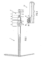
- the implement 1 shown in FIG. 1 is a light hoe which has a coupling nipple 2 firmly connected to it.
- the coupling nipple 2 has several sections 3 to 9, which differ on the one hand in the intended purpose and on the other hand in the cross-sectional shape and size.
- the first nipple section 3 on the implement side, shown on the left in FIG. 1, is substantially frustoconical, so that its cross-section increases towards the free nipple end.
- the first nipple section 3 is followed by a second nipple section 4 in the direction of the free nipple end, which is essentially cylindrical.
- a third nipple section 5 adjoins the second coupling section 4 towards the free nipple end and is essentially cylindrical. The diameter of this nipple section 5 is smaller than that of the adjacent second nipple section 4.
- the third nipple section 5 is followed by a fourth nipple section 6 towards the free nipple end, in which six ribs 11 are provided which are distributed uniformly around the circumference.
- the ribs 11 are formed in one piece with a hexagonal rod 12, on the edges of which they are arranged.
- the hexagonal rod 12 has the same regular hexagonal cross section throughout and is longer than the ribs 11; its area protruding toward the free nipple end forms a further nipple section 7.
- This nipple section 7 is followed by a short nipple section 8 which, like the previous nipple section 7, also has a continuously hexagonal, but smaller cross section than the previous nipple section 7.
- the nipple section 8 is adjoined by a further nipple section 9 which extends to the free nipple end and which corresponds in cross-sectional shape and size to the nipple section 7.
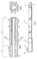
- FIG. 2 shows a coupling sleeve 13 which is suitable for the implement in FIG. 1 and is designed as a handle.
- Fig. 3 shows this sleeve on an enlarged scale.
- the sleeve 13 is hollow and designed in the interior so that the coupling nipple 2 of the implement 1 with its sections 4 to 9 can be inserted into the interior of the sleeve and fixed there.
- a sleeve section 14 is assigned to the nipple sections 4 and 5 in the interior of the sleeve 13, said sleeve section 14 being essentially cylindrical and having a diameter which essentially corresponds to the diameter of the second nipple section 4.
- a sleeve section 15 adjoins the sleeve section 14 in the interior of the sleeve 13 up to its rear end, in which there are provided three parallel guide ribs 16 which run symmetrically to the longitudinal axis of the sleeve 13 and which are formed in one piece with the sleeve wall.
- the guide ribs 16 correspond in cross section to that of an upright rectangle.
- the guide ribs 16 are arranged and their height is such that their narrow sides pointing into the interior of the coupling sleeve 13 each abut one of the six side surfaces of the nipple sections 7 and 9 as soon as the coupling nipple 2 is inserted into the interior of the coupling sleeve 13.
- the second nipple section 4 has six depressions 17 which are distributed uniformly around its circumference and which are essentially hemispherical.
- a latching element 18 designed as a radially acting screw is provided, which has a manually operable rotary knob 19.
- the rotary knob 19 has an inner cylindrical part 20, the edge of which, at least in some areas, is drawn inwards and engages behind the outwardly bent edge of a cylinder 21, which is firmly connected to the wall of the coupling sleeve 13, with the result that the latching element 18 can also be lost is when it has been brought completely out of engagement with the coupling nipple inserted into the interior of the coupling sleeve 13 by actuating the rotary knob 19.
- the radially acting locking member 18 is arranged so that it is aligned with one of the six recesses 17 in section 4 of the coupling nipple 2 as soon as it is inserted so far into the coupling sleeve 13 that its shoulder 10 strikes the end of the coupling sleeve 13 on the implement side. If the locking member 18, ie its knob 19 is now actuated, the tip of the radially acting locking member screw comes into engagement with one of the recesses 17. The interaction between the preferably Hemispherical free end of the locking slide screw with the hemispherical recess causes the coupling nipple 2 to be pulled into the coupling sleeve 13 until its shoulder 10 stops and is axially secured inside the sleeve 13.
- this extension shaft 22 carries a coupling sleeve 23, which essentially corresponds to the coupling sleeve according to FIG. 2, but a receptacle is provided on its end region facing away from the implement and pointing to the right in FIG. 5, in which the extension stem 22 is inserted and attached.
- the extension handle 22 has an extension 24 with a circumferential taper 25.
- the distance of the taper 25 to the free extension end corresponds to the distance of the locking member 18 from the implement-side coupling sleeve end, so that a coupling sleeve according to FIG. 2 can be pushed onto the extension 24 and secured by actuating the locking member.
- the extension arm 22 has the advantage that a working device equipped with a coupling sleeve according to FIG. 2 according to FIG. 1 can be converted into a stick device without great technical effort. For this purpose, only the coupling sleeve 13 is to be removed from the implement 1 after the locking member 18 has been released and the coupling sleeve 23 of the extension arm 22 has to be pushed onto the coupling nipple 2 of the implement 1 and then the locking member has to be actuated. In order to avoid that the coupling sleeve 13 designed as a handle is lost, it can then be pushed onto the extension 24 of the extension handle 22 and secured there by actuating the locking member.
- the coupling sleeves 13, 23 can have, at least in their end region facing away from the implement 1, axially extending grooves 26 which serve to absorb dirt when the coupling nipple 2 is fixed. Its wall can also or instead have at least one, preferably two opposing openings 27 through which dirt particles introduced into the interior of the sleeve can fall out.
- the openings 27 (cf. FIG. 3) can also be arranged and aligned with one another in such a way that they can be used to attach a strap or to carry out a wall hook.
Landscapes
- Engineering & Computer Science (AREA)
- Mechanical Engineering (AREA)
- Life Sciences & Earth Sciences (AREA)
- Soil Sciences (AREA)
- Environmental Sciences (AREA)
- Quick-Acting Or Multi-Walled Pipe Joints (AREA)
- Hand Tools For Fitting Together And Separating, Or Other Hand Tools (AREA)
Claims (13)
Priority Applications (1)
| Application Number | Priority Date | Filing Date | Title |
|---|---|---|---|
| AT83106635T ATE16230T1 (de) | 1982-08-17 | 1983-07-07 | Kupplungshuelse zum anschluss an ein einen schellkupplungsnippel aufweisendes arbeitsgeraet. |
Applications Claiming Priority (2)
| Application Number | Priority Date | Filing Date | Title |
|---|---|---|---|
| DE3230521 | 1982-08-17 | ||
| DE19823230521 DE3230521A1 (de) | 1982-08-17 | 1982-08-17 | Kupplungshuelse zum anschluss an ein einen schnellkupplungsnippel aufweisendes arbeitsgeraet |
Publications (2)
| Publication Number | Publication Date |
|---|---|
| EP0103094A1 EP0103094A1 (fr) | 1984-03-21 |
| EP0103094B1 true EP0103094B1 (fr) | 1985-10-30 |
Family
ID=6171023
Family Applications (1)
| Application Number | Title | Priority Date | Filing Date |
|---|---|---|---|
| EP83106635A Expired EP0103094B1 (fr) | 1982-08-17 | 1983-07-07 | Manchon d'accouplement pour la jonction à un outil de travail présentant un raccord à accouplement rapide |
Country Status (3)
| Country | Link |
|---|---|
| EP (1) | EP0103094B1 (fr) |
| AT (1) | ATE16230T1 (fr) |
| DE (2) | DE3230521A1 (fr) |
Families Citing this family (3)
| Publication number | Priority date | Publication date | Assignee | Title |
|---|---|---|---|---|
| EP3114914B1 (fr) | 2015-07-07 | 2018-12-19 | Kompernass Handelsgesellschaft MbH | Dispositif de couplage mecanique |
| DE102016014297B4 (de) | 2016-11-25 | 2026-05-28 | Stefan Grubmiller | Gartengerät mit 2 Stielen und messerartigen Zinken zur Bodenbearbeitung |
| DE102023110794A1 (de) * | 2023-04-26 | 2024-10-31 | Michael Engelen | Gartenhandgerät |
Family Cites Families (4)
| Publication number | Priority date | Publication date | Assignee | Title |
|---|---|---|---|---|
| US2212679A (en) * | 1937-09-27 | 1940-08-27 | Hoover Co | Dusting tool for suction cleaners |
| FR1103112A (fr) * | 1954-04-15 | 1955-10-31 | Fixation des tamponnoirs dans les manches | |
| FR1355656A (fr) * | 1963-02-04 | 1964-03-20 | Brosse Et J Dupont Reunis | Perfectionnements apportés à la fixation de manches sur des balais ou instruments similaires |
| DE2617621C2 (de) * | 1976-04-22 | 1982-11-18 | Gardena Kress + Kastner Gmbh, 7900 Ulm | System verschiedener Gartengeräte |
-
1982
- 1982-08-17 DE DE19823230521 patent/DE3230521A1/de not_active Withdrawn
-
1983
- 1983-07-07 EP EP83106635A patent/EP0103094B1/fr not_active Expired
- 1983-07-07 DE DE8383106635T patent/DE3361120D1/de not_active Expired
- 1983-07-07 AT AT83106635T patent/ATE16230T1/de not_active IP Right Cessation
Also Published As
| Publication number | Publication date |
|---|---|
| DE3361120D1 (en) | 1985-12-05 |
| EP0103094A1 (fr) | 1984-03-21 |
| DE3230521A1 (de) | 1984-02-23 |
| ATE16230T1 (de) | 1985-11-15 |
Similar Documents
| Publication | Publication Date | Title |
|---|---|---|
| DE2617621C2 (de) | System verschiedener Gartengeräte | |
| EP0332759A2 (fr) | Dispositif de fixation axiale pour la connexion d'éléments tubulaires | |
| EP0414002B1 (fr) | Outil de soudage | |
| EP0707923B1 (fr) | Couteau, notamment couteau d'ébavurage de pièces en matière plastique | |
| DE3040537C2 (de) | Vorrichtung zum Lösen einer Halte- oder Spannvorrichtung für ein zahnärztliches Werkzeug | |
| DE2617622C2 (de) | Kupplungsnippel zur Verbindung eines Arbeitsgerätes mit einem Stiel | |
| EP1137893B1 (fr) | Dispositif d'accouplement muni d'un systeme de blocage | |
| DE2804010A1 (de) | Brechstiftkupplung | |
| EP0428856B1 (fr) | Bielle de relevage pour tracteur | |
| EP0446448B1 (fr) | Dispositif d'assemblage pour tuyaux sous pression ou équivalents | |
| DE2555202C2 (de) | Schutzvorrichtung für Gelenkwellen | |
| DE2830945A1 (de) | System verschiedener gartengeraete | |
| DE1791013C2 (de) | Kupplung für den Anschluß eines zahnärztlichen Hand- oder Winkelstückes an einen als Kleinstmotor ausgebildeten elektrischen Antriebsmotor | |
| EP0717666B1 (fr) | Porte-brosse reglable en continu | |
| EP0103094A1 (fr) | Manchon d'accouplement pour la jonction à un outil de travail présentant un raccord à accouplement rapide | |
| DE29619438U1 (de) | Befestigungsvorrichtung für eine Gerätehandhabe für Gartengeräte | |
| DE69000857T2 (de) | Vorrichtung zum verhindern des sich loesens eines verschiebbar in einem aufnehmenden rohr sitzenden einschiebbaren rohrs und eine mit dieser vorrichtung versehene stuetze. | |
| DE3829526C2 (de) | Pleuelstangen-Kurbel-Vorrichtung, insbesondere zur Betätigung einer Luftklappe innerhalb einer Heiz- und Klimaanlage für Kraftfahrzeuge | |
| DE3921443C2 (fr) | ||
| DE2909469C2 (de) | Spannvorrichtung für chirurgische Werkzeuge | |
| DE1933166C3 (de) | Nabenbefestigung mit einer auf eine Welle aufgeschraubten Mutter | |
| DE9216760U1 (de) | Markiergerät zum Anbringen von Markierungen an Rohrmänteln | |
| DE3518661A1 (de) | Schraubenschluessel | |
| DE19806617A1 (de) | Ausbeulvorrichtung und Bearbeitungsteil für Ausbeulvorrichtung | |
| DE3335495A1 (de) | Kombinationswerkzeug |
Legal Events
| Date | Code | Title | Description |
|---|---|---|---|
| PUAI | Public reference made under article 153(3) epc to a published international application that has entered the european phase |
Free format text: ORIGINAL CODE: 0009012 |
|
| AK | Designated contracting states |
Designated state(s): AT BE CH DE FR GB IT LI LU NL SE |
|
| 17P | Request for examination filed |
Effective date: 19840302 |
|
| GRAA | (expected) grant |
Free format text: ORIGINAL CODE: 0009210 |
|
| AK | Designated contracting states |
Designated state(s): AT BE CH DE FR GB IT LI LU NL SE |
|
| REF | Corresponds to: |
Ref document number: 16230 Country of ref document: AT Date of ref document: 19851115 Kind code of ref document: T |
|
| REF | Corresponds to: |
Ref document number: 3361120 Country of ref document: DE Date of ref document: 19851205 |
|
| ITF | It: translation for a ep patent filed | ||
| ET | Fr: translation filed | ||
| PG25 | Lapsed in a contracting state [announced via postgrant information from national office to epo] |
Ref country code: LU Free format text: LAPSE BECAUSE OF NON-PAYMENT OF DUE FEES Effective date: 19860731 |
|
| PLBE | No opposition filed within time limit |
Free format text: ORIGINAL CODE: 0009261 |
|
| STAA | Information on the status of an ep patent application or granted ep patent |
Free format text: STATUS: NO OPPOSITION FILED WITHIN TIME LIMIT |
|
| 26N | No opposition filed | ||
| ITTA | It: last paid annual fee | ||
| PGFP | Annual fee paid to national office [announced via postgrant information from national office to epo] |
Ref country code: NL Payment date: 19930731 Year of fee payment: 11 |
|
| PGFP | Annual fee paid to national office [announced via postgrant information from national office to epo] |
Ref country code: CH Payment date: 19930819 Year of fee payment: 11 |
|
| PG25 | Lapsed in a contracting state [announced via postgrant information from national office to epo] |
Ref country code: LI Effective date: 19940731 Ref country code: CH Effective date: 19940731 |
|
| EAL | Se: european patent in force in sweden |
Ref document number: 83106635.2 |
|
| PG25 | Lapsed in a contracting state [announced via postgrant information from national office to epo] |
Ref country code: NL Effective date: 19950201 |
|
| NLV4 | Nl: lapsed or anulled due to non-payment of the annual fee | ||
| REG | Reference to a national code |
Ref country code: CH Ref legal event code: PL |
|
| PGFP | Annual fee paid to national office [announced via postgrant information from national office to epo] |
Ref country code: BE Payment date: 19950809 Year of fee payment: 13 |
|
| PG25 | Lapsed in a contracting state [announced via postgrant information from national office to epo] |
Ref country code: BE Effective date: 19960731 |
|
| BERE | Be: lapsed |
Owner name: GARDENA KRESS + KASTNER G.M.B.H. Effective date: 19960731 |
|
| PGFP | Annual fee paid to national office [announced via postgrant information from national office to epo] |
Ref country code: GB Payment date: 19970623 Year of fee payment: 15 |
|
| PGFP | Annual fee paid to national office [announced via postgrant information from national office to epo] |
Ref country code: FR Payment date: 19970717 Year of fee payment: 15 |
|
| PGFP | Annual fee paid to national office [announced via postgrant information from national office to epo] |
Ref country code: SE Payment date: 19970722 Year of fee payment: 15 Ref country code: AT Payment date: 19970722 Year of fee payment: 15 |
|
| PG25 | Lapsed in a contracting state [announced via postgrant information from national office to epo] |
Ref country code: GB Free format text: LAPSE BECAUSE OF NON-PAYMENT OF DUE FEES Effective date: 19980707 Ref country code: AT Free format text: LAPSE BECAUSE OF NON-PAYMENT OF DUE FEES Effective date: 19980707 |
|
| PG25 | Lapsed in a contracting state [announced via postgrant information from national office to epo] |
Ref country code: SE Free format text: LAPSE BECAUSE OF NON-PAYMENT OF DUE FEES Effective date: 19980708 |
|
| GBPC | Gb: european patent ceased through non-payment of renewal fee |
Effective date: 19980707 |
|
| EUG | Se: european patent has lapsed |
Ref document number: 83106635.2 |
|
| PG25 | Lapsed in a contracting state [announced via postgrant information from national office to epo] |
Ref country code: FR Free format text: LAPSE BECAUSE OF NON-PAYMENT OF DUE FEES Effective date: 19990331 |
|
| REG | Reference to a national code |
Ref country code: FR Ref legal event code: ST |
|
| PGFP | Annual fee paid to national office [announced via postgrant information from national office to epo] |
Ref country code: DE Payment date: 19990720 Year of fee payment: 17 |
|
| PG25 | Lapsed in a contracting state [announced via postgrant information from national office to epo] |
Ref country code: DE Free format text: LAPSE BECAUSE OF NON-PAYMENT OF DUE FEES Effective date: 20010501 |