EP0103162B1 - Dispositif de mesure et de commande pour charges suspendues à des câbles, en particulier pour soulever des décors de théatre - Google Patents
Dispositif de mesure et de commande pour charges suspendues à des câbles, en particulier pour soulever des décors de théatre Download PDFInfo
- Publication number
- EP0103162B1 EP0103162B1 EP83107865A EP83107865A EP0103162B1 EP 0103162 B1 EP0103162 B1 EP 0103162B1 EP 83107865 A EP83107865 A EP 83107865A EP 83107865 A EP83107865 A EP 83107865A EP 0103162 B1 EP0103162 B1 EP 0103162B1
- Authority
- EP
- European Patent Office
- Prior art keywords
- measuring
- cable
- control device
- rope
- sensors
- Prior art date
- Legal status (The legal status is an assumption and is not a legal conclusion. Google has not performed a legal analysis and makes no representation as to the accuracy of the status listed.)
- Expired
Links
- 230000003287 optical effect Effects 0.000 claims abstract description 35
- 230000004044 response Effects 0.000 claims abstract description 8
- 238000004804 winding Methods 0.000 claims abstract 7
- 238000006243 chemical reaction Methods 0.000 claims description 4
- WFKWXMTUELFFGS-UHFFFAOYSA-N tungsten Chemical compound [W] WFKWXMTUELFFGS-UHFFFAOYSA-N 0.000 claims description 3
- 238000005259 measurement Methods 0.000 description 16
- 238000011156 evaluation Methods 0.000 description 13
- 230000004913 activation Effects 0.000 description 5
- 229910000831 Steel Inorganic materials 0.000 description 4
- 239000010959 steel Substances 0.000 description 4
- 238000010586 diagram Methods 0.000 description 3
- 230000004304 visual acuity Effects 0.000 description 3
- 230000004907 flux Effects 0.000 description 2
- 102000002508 Peptide Elongation Factors Human genes 0.000 description 1
- 108010068204 Peptide Elongation Factors Proteins 0.000 description 1
- 241001310793 Podium Species 0.000 description 1
- 238000009960 carding Methods 0.000 description 1
- 238000005034 decoration Methods 0.000 description 1
- 230000007547 defect Effects 0.000 description 1
- 238000001514 detection method Methods 0.000 description 1
- 239000000428 dust Substances 0.000 description 1
- 230000006870 function Effects 0.000 description 1
- 230000001771 impaired effect Effects 0.000 description 1
- 239000000463 material Substances 0.000 description 1
- 238000000034 method Methods 0.000 description 1
- 230000003449 preventive effect Effects 0.000 description 1
- 230000008569 process Effects 0.000 description 1
- 230000001960 triggered effect Effects 0.000 description 1
Images

Classifications
-
- B—PERFORMING OPERATIONS; TRANSPORTING
- B66—HOISTING; LIFTING; HAULING
- B66B—ELEVATORS; ESCALATORS OR MOVING WALKWAYS
- B66B5/00—Applications of checking, fault-correcting, or safety devices in elevators
- B66B5/02—Applications of checking, fault-correcting, or safety devices in elevators responsive to abnormal operating conditions
- B66B5/14—Applications of checking, fault-correcting, or safety devices in elevators responsive to abnormal operating conditions in case of excessive loads
- B66B5/145—Applications of checking, fault-correcting, or safety devices in elevators responsive to abnormal operating conditions in case of excessive loads electrical
-
- A—HUMAN NECESSITIES
- A63—SPORTS; GAMES; AMUSEMENTS
- A63J—DEVICES FOR THEATRES, CIRCUSES, OR THE LIKE; CONJURING APPLIANCES OR THE LIKE
- A63J1/00—Stage arrangements
- A63J1/02—Scenery; Curtains; Other decorations; Means for moving same
- A63J1/028—Means for moving hanging scenery
-
- B—PERFORMING OPERATIONS; TRANSPORTING
- B66—HOISTING; LIFTING; HAULING
- B66C—CRANES; LOAD-ENGAGING ELEMENTS OR DEVICES FOR CRANES, CAPSTANS, WINCHES, OR TACKLES
- B66C13/00—Other constructional features or details
- B66C13/18—Control systems or devices
- B66C13/46—Position indicators for suspended loads or for crane elements
-
- B—PERFORMING OPERATIONS; TRANSPORTING
- B66—HOISTING; LIFTING; HAULING
- B66D—CAPSTANS; WINCHES; TACKLES, e.g. PULLEY BLOCKS; HOISTS
- B66D1/00—Rope, cable, or chain winding mechanisms; Capstans
- B66D1/28—Other constructional details
- B66D1/40—Control devices
- B66D1/48—Control devices automatic
- B66D1/485—Control devices automatic electrical
-
- G—PHYSICS
- G01—MEASURING; TESTING
- G01B—MEASURING LENGTH, THICKNESS OR SIMILAR LINEAR DIMENSIONS; MEASURING ANGLES; MEASURING AREAS; MEASURING IRREGULARITIES OF SURFACES OR CONTOURS
- G01B11/00—Measuring arrangements characterised by the use of optical techniques
- G01B11/02—Measuring arrangements characterised by the use of optical techniques for measuring length, width or thickness
- G01B11/04—Measuring arrangements characterised by the use of optical techniques for measuring length, width or thickness specially adapted for measuring length or width of objects while moving
- G01B11/043—Measuring arrangements characterised by the use of optical techniques for measuring length, width or thickness specially adapted for measuring length or width of objects while moving for measuring length
Definitions
- the invention relates to a measuring and control device for loads attached to ropes, in particular for theater point trains, with a rope drum, with a first measuring device that detects the angular position and / or speed of the rope drum, with a motor driving the rope drum, with a second measuring device, scans the optical markings of the rope, with an evaluation device that compares the measurement results of both measuring devices with one another, and with a control device that controls the motor as a function of predefined setpoints of the extended rope length and the determined, actually extended rope length.
- Such a measuring and control device is described in DE-A 3103708. However, there is no information given on how the sensors of the second measuring device are to be arranged in order to achieve exact measurement and control under the conditions that occur in practice.
- a depth indicator device is known in which changes in a relative position from the magnetic yoke to the conveying rope cause changes in the magnetic flux due to the rope profiling, these changes in the magnetic flux being measured and used for control purposes.
- DE-A 1 478763 describes a device for displaying the status and programmed destination travel in theater facilities, such as Decorative trains, point trains, curtains, podiums, stage wagons and revolving stages are described, in which the actual value of the extended rope length is recorded by a slotted disc with sensors on the rope drum. In a single computer for all monitored or controlled theater facilities, these actual values are compared with target values, from which corresponding control signals for the drive motor (s) are generated.
- a disadvantage of this device is that the measuring accuracy and thus also the control accuracy are limited on the one hand by the relatively coarse resolution of the angle encoder or the slotted disc with the encoders, and on the other hand that rope elongations caused by loading cannot be taken into account. On the one hand, this leads to imprecise movement sequences, inaccurate positions of headlights, decorations, etc., and also to undesired readjustments. Also critical strains of the ropes due to material defects, excessive load etc. cannot be determined in this known system. As a result, there is no possibility of taking preventive measures against accidents caused by a broken rope.
- the object of the invention is to improve the measuring and control device of the type mentioned at the outset in such a way that the measuring and control accuracy is improved, in particular taking into account the rope elongation.
- the second measuring device contains a plurality of optical measuring sensors, the spacings of which are selected such that a maximum of two of them each detect a rope marking.
- the resolving power is thus only limited by the width of the markings, the rope length actually extended, taking into account the rope elongation, being measured and used for control and not just the assumed rope length of the unstretched rope.
- the detection of the rope elongation also increases safety, since an impending rope break is always preceded by excessive elongation, which can be detected.
- the measuring and control principle of the invention can thus be used wherever loads on ropes are to be moved very precisely, for example also in lifts, cranes, etc.
- the optical sensors are arranged one behind the other in the longitudinal direction of the rope, their distance corresponding to the mutual distance of the rope markings of the unstretched rope plus n times an increment, where n is the integer index of the respective sensor.
- the distances between the individual sensors are continuously increasing.
- the distance between the zeroth and the first sensor corresponds exactly to the distance between two adjacent rope markings, so that when the rope is not stretched, these two sensors always respond together.
- the distance between the first and the second sensor is then the distance between two adjacent rope markings plus a preselected value (Al). If the rope is in the area between three neighboring rope markings, i.e. stretched by the amount Al in the range of two measuring intervals, the zero and the second sensor respond simultaneously.
- the distance between the zeroth and the first sensor is already equal to the length (I) between two be neighboring rope markings of the unstretched rope plus the increment Al.
- the distance between the zeroth and the first sensor is already equal to the length (I) between two be neighboring rope markings of the unstretched rope plus the increment Al.
- the distances between adjacent optical sensors are determined in the manner of a vernier division, based on the distance between the rope markings of the unstretched rope.
- the sensors are preferably arranged in side openings of a tube, inside of which a piece of the rope runs.
- the sensors can be arranged along a straight line, but they can also be arranged on a screw line running around the pipe.
- a particularly good optically scannable and permanent rope marking is obtained by applying the rope markings as a helical marking in such a way that one cardele of the rope is of a different color than the other cardelees. It has been found to be particularly advantageous for steel cables to produce the carding tubes which form the marking from tungsten wire. This differs significantly from the other steel cardels even when contaminated by oil, dust or the like, whereby the color difference is not impaired by downforce etc.
- the second measuring device contains an evaluation device which is connected downstream of the optical sensors and which can be activated by dynamic response of a predetermined optical sensor and which detects the simultaneous response of the maximum of one further sensor. Every time a rope marking passes the predetermined optical measuring sensor, for example the zeroth measuring sensor, the second measuring device is activated and it is checked whether at this point in time another rope marking is opposite one of the further measuring sensors. The rope elongation can then be determined from this.
- the evaluation device has a parallel input / parallel output register, the activation or clock input of which is connected to the predetermined optical measuring sensor and the data inputs of which are each connected to one of the other optical measuring sensors.
- the predetermined optical sensor for example the zero sensor
- the measurement process is initiated and it is determined whether one or which of the other sensors detects a rope marking at this point in time, which is then written into the corresponding register space.
- an advantageous embodiment of the invention provides that a read-only memory is connected downstream of the register, which is determined by the content of the register - possibly according to a code Conversion by means of a demultiplexer - is addressable, with a predetermined multiplication factor being stored under each address, and that a multiplier is provided, the inputs of which are connected on the one hand to the output of the read-only memory and on the other hand to the first measuring device for the angular position of the side drum, the Output of the multiplier corresponds to the rope length actually extended.
- the first measuring device specifies a basic value for the extended rope length of the unstretched rope, a multiplication factor being determined by means of the rope elongation obtained by the second measuring device, by which the basic value of the extended rope length is multiplied in order to increase the actually extended rope length taking into account the elongation receive.
- the read-only memory is preferably a programmable read-only memory (PROM).
- PROM programmable read-only memory
- a comparator is provided, the inputs of which are connected on the one hand to a further read-only memory for a predetermined permissible rope elongation and on the other hand to the output of the second measuring device and which, depending on the comparison, generates a warning and / or control signal.
- a comparator is provided, the inputs of which are connected on the one hand to a further read-only memory for a predetermined permissible rope elongation and on the other hand to the output of the second measuring device and which, depending on the comparison, generates a warning and / or control signal.
- a rope 10 is shown, the upper end of which is attached to a rope drum (not shown).
- the rope 10 is preferably a struck steel cable, the individual Kar deelen 12, 13, 14 are struck from individual steel wires.
- the rope 10 has, at regular intervals, optically scannable rope markings which, according to the preferred exemplary embodiment shown in FIG. 1, are applied in such a way that one cardeleus 11 is of a different color than the other cardelees 12, 13, 14. It is particularly advantageous to form the card stock 11 representing the rope marking from tungsten wire.
- the cardeleus 11 reappears after a distance 1 on the same side of the rope 10, so that, in the case of sensors arranged in a straight line, the distance between the individual rope markings recognizable there is 1.
- a load (not shown) can be attached to the lower end of the rope 10.
- the rope 10 runs over a certain length within a tube 20 which has openings for receiving optical sensors 21, 22, 23 and 24, respectively.
- the number of sensors can be any, depending on the measurement accuracy requirements.
- the minimum number of optical sensors is two, but in this case it can only be determined whether the rope 10 has a predetermined elongation or not.
- the sensors 21 to 24 are arranged along a straight line in the longitudinal direction of the rope.
- not only one cardeleus 11 has to be designed as a rope marking. It is also conceivable to use several, but not adjacent, cardels as rope marking.
- the mutual distance between the individual optical sensors 21 to 24 in relation to the distance of the rope markings is particularly important.
- the respective distance between the individual optical sensors is selected so that a maximum of two sensors can each detect a rope marking.
- the distance is selected as follows: The distance between the sensors 21 and 22 is 1 + an increment A1.
- the distance between the sensors 22 and 23 is 1 + 2 Al; the distance between the sensors 23 and 24 is 1 +3 ⁇ l. If there are n sensors, the distance between sensor n-1 and sensor n is then 1 + (n-I) 01. 1 is always the distance between two adjacent rope markings.
- the rope 10 passes the sensors 21 .. .24 a maximum of one rope marking at a time opposite a sensor in such a way that it is detected by it. If the rope 10 is now stretched by a load in such a way that it is elongated by the amount ⁇ l in each case over the length 1, the sensor 21 and the sensor 22 are each facing a rope marking at a time. At this point in time, there is no other rope marking to the other sensors, because in the area of the sensor 23, for example, the corresponding rope marking is still 01 in front of the sensor.
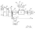
- the outputs of the optical sensors 21, 22, 23, 24 etc. are each connected to inputs 31, 32, 33, 34 etc. of an evaluation device 30.
- This evaluation device is explained in more detail in connection with FIG. 2.
- the evaluation device 30 receives the measurement result of the optical measurement sensors 21... 24 and thus the measurement result of the “second measurement device” via these inputs 31, 32, etc.
- the signals of the first measuring device which represent the angular position of the cable drum, are transmitted to another input of the evaluation device 30 via the line (s) 36. From the measured values of the first and second measuring devices, the evaluation device then determines the actually extended rope length, which is then output via line 38. In addition, upper and lower limit positions of the cable 10 can also be input to the evaluation device 30 via a line 37, so that the evaluation device 30 can ensure that the cable 10 is not moved beyond these points. If the evaluation device 30 takes over the control of the drive motor for the cable drum, a signal appears at the output 39 which corresponds to the target speed of the drive motor. Finally, an alarm signal, which may also stop the motor, is output on line 40 if excessive rope elongation has been determined.
- FIG. 2 shows a more detailed block diagram of the evaluation device 30.
- the outputs of the measuring sensors 21, 22 etc. are fed to a parallel input / parallel output register 41 (parallel input / output; PIO).
- PIO parallel input / output
- the output of the sensor 21 is connected to an activation or clock input of the register 41, while the other sensors 22 ... 24 are connected to the data inputs.
- the register 41 only accepts data from the sensors 22, 23, etc., when the sensor 21 has responded.
- the outputs of the register 41 are connected via a demultiplexer 42 to address inputs of a read-only memory 43, which is preferably a programmable read-only memory (PROM).
- the demultiplexer 42 performs a code conversion here.
- Specified multiplication factors are stored in the read-only memory 43 under each storage location, with a specific value ultimately being assigned to each response of a specific sensor and thus to each rope elongation.
- These multiplication factors are fed to a multiplier 44, which receives the measurement result of the first measuring device for the drum position at its other multiplication input. In the specific exemplary embodiment, this measurement result is obtained via a forward-backward counter 45, the counter input of which is fed via line 36 to the pulses of the angle encoder of the cable drum.
- the counting direction is determined via a control input 49, which is acted upon by the direction of rotation of the motor. For example, when the rope 10 is lowered, the counter 45 is operated as an up counter, while when the rope 10 is opened, the counter 45 is operated as a down counter. The counter 45 can still be reset to its zero position via an input 50.
- a comparator 47 is also provided, to which, on the one hand, the output signals of the demultiplexer 42 are fed and, on the other hand, predetermined values for the rope elongation from a further read-only memory 48. If the measured rope elongation exceeds the value predefined in the read-only memory 48, the comparator 47 emits on line 40 an alarm signal which warns the operator of the measuring and control device and / or switches off the engine.
- Read-only memory 48 can also be a programmable read-only memory (PROM).
- the optical measuring sensors 21, 22 etc. are used to determine the rope elongation, the measuring accuracy or the resolving power being limited by the accuracy of the angle encoder.
- the measuring accuracy can be improved by the second measuring device with the optical sensors.
- the mutual distances between the optical sensors are determined in the manner of a vernier division.
- the individual measuring intervals between two segments or teeth of the angle encoder are then divided by the optical sensors.
- the measurement result of the optical measuring sensors must be added to the measurement result of the angle encoder, so that an adder is then used instead of the multiplier 44.
- the read-only memory 43 can also be omitted under certain circumstances.
- the sensor 21 is then also to be connected to a data input of the register 41, while the takeover pulse for the register 41 at its activation or clock input comes from an external source, for example a clock generator.
Landscapes
- Engineering & Computer Science (AREA)
- Mechanical Engineering (AREA)
- Physics & Mathematics (AREA)
- General Physics & Mathematics (AREA)
- Automation & Control Theory (AREA)
- Control And Safety Of Cranes (AREA)
- Length Measuring Devices By Optical Means (AREA)
- Length Measuring Devices With Unspecified Measuring Means (AREA)
Claims (11)
Priority Applications (1)
| Application Number | Priority Date | Filing Date | Title |
|---|---|---|---|
| AT83107865T ATE27134T1 (de) | 1982-08-13 | 1983-08-09 | Mess- und steuereinrichtung fuer an seilen befestigte lasten, insbesondere fuer theaterpunktzuege. |
Applications Claiming Priority (2)
| Application Number | Priority Date | Filing Date | Title |
|---|---|---|---|
| DE3230213 | 1982-08-13 | ||
| DE19823230213 DE3230213A1 (de) | 1982-08-13 | 1982-08-13 | Mess- und steuereinrichtung fuer an seilen befestigte lasten, insbesondere fuer theaterpunktzuege |
Publications (3)
| Publication Number | Publication Date |
|---|---|
| EP0103162A2 EP0103162A2 (fr) | 1984-03-21 |
| EP0103162A3 EP0103162A3 (en) | 1985-09-18 |
| EP0103162B1 true EP0103162B1 (fr) | 1987-05-13 |
Family
ID=6170832
Family Applications (1)
| Application Number | Title | Priority Date | Filing Date |
|---|---|---|---|
| EP83107865A Expired EP0103162B1 (fr) | 1982-08-13 | 1983-08-09 | Dispositif de mesure et de commande pour charges suspendues à des câbles, en particulier pour soulever des décors de théatre |
Country Status (3)
| Country | Link |
|---|---|
| EP (1) | EP0103162B1 (fr) |
| AT (1) | ATE27134T1 (fr) |
| DE (2) | DE3230213A1 (fr) |
Families Citing this family (13)
| Publication number | Priority date | Publication date | Assignee | Title |
|---|---|---|---|---|
| EP0525230A1 (fr) * | 1991-07-30 | 1993-02-03 | Anglo American Corporation of South Africa Limited | Procédure et appareil pour surveiller un câble d'extraction |
| DE4228392A1 (de) * | 1992-07-06 | 1994-01-13 | Liebherr Werk Nenzing | Verfahren zur Steuerung des Greifers eines Seilbaggers |
| DE4244732C2 (de) * | 1992-12-09 | 1996-08-14 | Deutsche Tiefbohr Ag | Verfahren zur Steuerung eines seilgetriebenen Hebezeuges |
| DE10033626A1 (de) * | 2000-07-11 | 2002-01-24 | Mannesmann Rexroth Ag | Prospektkonterzug |
| DE10041035A1 (de) * | 2000-08-22 | 2002-03-07 | Heinrich Bader | Vorrichtung und Verfahren zum Mechanisieren von Seil- und Prospektzügen, insbesondere im Bühnenbereich |
| US20030062226A1 (en) | 2001-10-03 | 2003-04-03 | Stucky Paul A. | Elevator load bearing assembly having a ferromagnetic element that provides an indication of local strain |
| US20030062225A1 (en) | 2001-10-03 | 2003-04-03 | Stucky Paul A. | Elevator load bearing assembly having a detectable element that is indicative of local strain |
| US7117981B2 (en) * | 2001-12-19 | 2006-10-10 | Otis Elevator Company | Load bearing member for use in an elevator system having external markings for indicating a condition of the assembly |
| CN102374854A (zh) * | 2011-11-02 | 2012-03-14 | 中国船舶重工集团公司第七一〇研究所 | 一种缆长监测装置 |
| CN105439022B (zh) * | 2014-08-05 | 2017-12-05 | 北京金顺帆科技有限公司 | 一种直升机绞车控制系统 |
| EP3470363B1 (fr) * | 2017-10-16 | 2025-01-15 | SkySails Power GmbH | Procédé et système de commande d'enroulement ou de déroulement d'une section de câble sur ou d'un tambour rotatif |
| US12434944B2 (en) * | 2019-03-29 | 2025-10-07 | Inventio Ag | Determination of the state of a suspension means |
| US11486992B2 (en) * | 2019-11-15 | 2022-11-01 | Stage Lighting Patents, LLC | Rotating range sensor to measure truss vertical height for stage configurations |
Family Cites Families (3)
| Publication number | Priority date | Publication date | Assignee | Title |
|---|---|---|---|---|
| DE1030982B (de) * | 1955-09-17 | 1958-05-29 | Siemens Ag | Magnetisch-elektrische Teufenzeigereinrichtung fuer Foerderschaechte mit gleichzeitiger Geschwindigkeitsangabe |
| FR1438839A (fr) * | 1965-06-29 | 1966-05-13 | Stahlinstitut Wissenschaftlich | Procédé pour la mesure sans contact de l'allongement visible d'objets |
| DE2649370C3 (de) * | 1976-10-29 | 1981-03-26 | MAN Gutehoffnungshütte GmbH, 4200 Oberhausen | Vorrichtung zur Gleichlaufregelung einer Punktseilzugeinrichtung für Theaterbühnen |
-
1982
- 1982-08-13 DE DE19823230213 patent/DE3230213A1/de not_active Withdrawn
-
1983
- 1983-08-09 AT AT83107865T patent/ATE27134T1/de not_active IP Right Cessation
- 1983-08-09 DE DE8383107865T patent/DE3371497D1/de not_active Expired
- 1983-08-09 EP EP83107865A patent/EP0103162B1/fr not_active Expired
Also Published As
| Publication number | Publication date |
|---|---|
| DE3230213A1 (de) | 1984-02-23 |
| EP0103162A3 (en) | 1985-09-18 |
| DE3371497D1 (en) | 1987-06-19 |
| EP0103162A2 (fr) | 1984-03-21 |
| ATE27134T1 (de) | 1987-05-15 |
Similar Documents
| Publication | Publication Date | Title |
|---|---|---|
| EP0848804B1 (fr) | Capteur d'angle absolu de braquage | |
| EP0388390B1 (fr) | Système de mesure incrémentiel | |
| EP0103162B1 (fr) | Dispositif de mesure et de commande pour charges suspendues à des câbles, en particulier pour soulever des décors de théatre | |
| DE69307135T2 (de) | Positionsskala und optischer lesesensor zum lesen derselben | |
| DE3325125C1 (de) | Anordnung zur Markierung von Fehlstellen an schnell laufenden Materialbahnen | |
| DE2225153B2 (de) | Warneinrichtung zur Erzeugung eines Warnsignales bei fehlerhaftem Zustand eines Kranes | |
| DE602005002763T2 (de) | Kodierer und Steuervorrichtung für Motor | |
| DE3219132C2 (de) | Direktschärmaschine mit einer Einrichtung zum Regeln der Schärgeschwindigkeit | |
| DE2330415A1 (de) | Verfahren zum beruehrungslosen messen eines bewegten gegenstandes und vorrichtung zur durchfuehrung des verfahrens | |
| DE2521618B1 (de) | Vorrichtung zum Messen oder Einstellen von zweidimensionalen Lagekoordinaten | |
| DE102017119301A1 (de) | Vorrichtung und Verfahren zur Ermittlung des Verschleisszustandes einer Kette | |
| AT394781B (de) | Inkrementales messsystem | |
| EP0108949A1 (fr) | Dispositif pour enregistrer la position et/ou la vitesse d'un piston d'un vérin | |
| DE102007038013B4 (de) | Verfahren zur optischen Messung von Geschwindigkeiten und Sensor zur optischen Messung von Geschwindigkeiten | |
| DE2601274A1 (de) | Detektorvorrichtung | |
| EP4019980A1 (fr) | Dispositif de détermination des données permettant de déterminer une vitesse d'un véhicule, dispositif d'évaluation et procédé correspondant | |
| DE10151234B4 (de) | Umdrehungszähler zum Ermitteln einer Umdrehungszahl eines um eine Drehachse drehbaren Drehelements | |
| DE3509102C2 (de) | Meßeinrichtung | |
| DE102014223251B3 (de) | Verfahren und Vorrichtung zur Erfassung, Auswertung und Darstellung von Messwerten von Motoren elektrischer Antriebe | |
| EP0475085A2 (fr) | Procédé de mesure pour déterminer l'élongation de rupture d'un échantillon sous tension pendant un essai de tension contrôlé par ordinateur | |
| EP3721238B1 (fr) | Détermination de gradient pour mesures de vitesse de rotation | |
| DE3522809C2 (fr) | ||
| EP0802467A2 (fr) | Méthode et moyens pour le positionnement d'un appareil | |
| EP3583257B1 (fr) | Procédé de fonctionnement d'une carde, et carde | |
| DE2839880C3 (de) | Vorrichtung zur Bestimmung der Lageänderung eine Gegenstandes |
Legal Events
| Date | Code | Title | Description |
|---|---|---|---|
| PUAI | Public reference made under article 153(3) epc to a published international application that has entered the european phase |
Free format text: ORIGINAL CODE: 0009012 |
|
| AK | Designated contracting states |
Designated state(s): AT BE CH DE FR IT LI NL SE |
|
| PUAL | Search report despatched |
Free format text: ORIGINAL CODE: 0009013 |
|
| AK | Designated contracting states |
Designated state(s): AT BE CH DE FR IT LI NL SE |
|
| 17P | Request for examination filed |
Effective date: 19850814 |
|
| 17Q | First examination report despatched |
Effective date: 19860926 |
|
| GRAA | (expected) grant |
Free format text: ORIGINAL CODE: 0009210 |
|
| AK | Designated contracting states |
Kind code of ref document: B1 Designated state(s): AT BE CH DE FR IT LI NL SE |
|
| PG25 | Lapsed in a contracting state [announced via postgrant information from national office to epo] |
Ref country code: NL Effective date: 19870513 Ref country code: IT Free format text: LAPSE BECAUSE OF FAILURE TO SUBMIT A TRANSLATION OF THE DESCRIPTION OR TO PAY THE FEE WITHIN THE PRESCRIBED TIME-LIMIT;WARNING: LAPSES OF ITALIAN PATENTS WITH EFFECTIVE DATE BEFORE 2007 MAY HAVE OCCURRED AT ANY TIME BEFORE 2007. THE CORRECT EFFECTIVE DATE MAY BE DIFFERENT FROM THE ONE RECORDED. Effective date: 19870513 |
|
| REF | Corresponds to: |
Ref document number: 27134 Country of ref document: AT Date of ref document: 19870515 Kind code of ref document: T |
|
| PG25 | Lapsed in a contracting state [announced via postgrant information from national office to epo] |
Ref country code: SE Effective date: 19870531 |
|
| ET | Fr: translation filed | ||
| REF | Corresponds to: |
Ref document number: 3371497 Country of ref document: DE Date of ref document: 19870619 |
|
| NLV1 | Nl: lapsed or annulled due to failure to fulfill the requirements of art. 29p and 29m of the patents act | ||
| PLBE | No opposition filed within time limit |
Free format text: ORIGINAL CODE: 0009261 |
|
| STAA | Information on the status of an ep patent application or granted ep patent |
Free format text: STATUS: NO OPPOSITION FILED WITHIN TIME LIMIT |
|
| 26N | No opposition filed | ||
| PG25 | Lapsed in a contracting state [announced via postgrant information from national office to epo] |
Ref country code: AT Effective date: 19880809 |
|
| PG25 | Lapsed in a contracting state [announced via postgrant information from national office to epo] |
Ref country code: LI Effective date: 19880831 Ref country code: CH Effective date: 19880831 Ref country code: BE Effective date: 19880831 |
|
| BERE | Be: lapsed |
Owner name: BAYERISCHE BUHNENBAU G.M.B.H. Effective date: 19880831 |
|
| PG25 | Lapsed in a contracting state [announced via postgrant information from national office to epo] |
Ref country code: FR Free format text: LAPSE BECAUSE OF NON-PAYMENT OF DUE FEES Effective date: 19890428 |
|
| REG | Reference to a national code |
Ref country code: CH Ref legal event code: PL |
|
| PG25 | Lapsed in a contracting state [announced via postgrant information from national office to epo] |
Ref country code: DE Effective date: 19890503 |
|
| REG | Reference to a national code |
Ref country code: FR Ref legal event code: ST |