EP0103166A2 - Vorrichtung zur Zerstäubung eines Fluidums, besonders eines Bearbeitungsschmieröls - Google Patents
Vorrichtung zur Zerstäubung eines Fluidums, besonders eines Bearbeitungsschmieröls Download PDFInfo
- Publication number
- EP0103166A2 EP0103166A2 EP83107883A EP83107883A EP0103166A2 EP 0103166 A2 EP0103166 A2 EP 0103166A2 EP 83107883 A EP83107883 A EP 83107883A EP 83107883 A EP83107883 A EP 83107883A EP 0103166 A2 EP0103166 A2 EP 0103166A2
- Authority
- EP
- European Patent Office
- Prior art keywords
- socket
- fluid
- opening
- conduit
- bore
- Prior art date
- Legal status (The legal status is an assumption and is not a legal conclusion. Google has not performed a legal analysis and makes no representation as to the accuracy of the status listed.)
- Granted
Links
Images
Classifications
-
- F—MECHANICAL ENGINEERING; LIGHTING; HEATING; WEAPONS; BLASTING
- F16—ENGINEERING ELEMENTS AND UNITS; GENERAL MEASURES FOR PRODUCING AND MAINTAINING EFFECTIVE FUNCTIONING OF MACHINES OR INSTALLATIONS; THERMAL INSULATION IN GENERAL
- F16N—LUBRICATING
- F16N7/00—Arrangements for supplying oil or unspecified lubricant from a stationary reservoir or the equivalent in or on the machine or member to be lubricated
- F16N7/30—Arrangements for supplying oil or unspecified lubricant from a stationary reservoir or the equivalent in or on the machine or member to be lubricated the oil being fed or carried along by another fluid
- F16N7/32—Mist lubrication
- F16N7/34—Atomising devices for oil
Definitions
- the present invention relates to an apparatus for spraying a fluid, in particular a machining lubricant, comprising at least one spray nozzle to which the fluid to be sprayed, on the one hand, and the propellant fluid are conveyed of this fluid, on the other hand.
- Apparatuses of the aforementioned type are known in which the supply of the spray nozzle is ensured by two flexible coaxial conduits.
- the external flexible conduit is crossed at its end opposite to that at which it is fixed to the spray nozzle by a radial passage leading to the internal coaxial conduit.
- the two flexible conduits cannot exert a rotational movement on themselves at the end at which they are connected to the spraying apparatus.
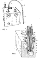
- Figure 1 is a perspective view of an apparatus spraying machining lubricant
- Figure 2 is a section of a detail of this device on an enlarged scale.
- the apparatus shown in FIG. 1 comprises a housing 1 containing its various constituent elements, reservoir of fluid to be sprayed, regulators, control devices, etc. which will not be described here in more detail, being known and foreign to the present invention.
- This device comprises a hose generally designated by 2, constituted by a flexible metal shielded sheath 3 and by two coaxial conduits 4 and 5 terminating through a rigid body 6 at a spray nozzle 7.
- the outer conduit 4 is intended to convey the fluid to be sprayed, for example a cutting oil emulsified by water, while the inner conduit 5 is intended to convey the propellant fluid of the fluid to be sprayed, for example pressurized air.
- the illustrated device comprises, housed inside the housing 1, a solid parallelepiped body 8 in which are arranged two conduits 9 and 10 parallel to the major axis of the body 8.
- the latter has one or more holes 11 perpendicular to the conduits 9 and 10 which each open into the conduit 10 and each bite tangentially on the conduit 9. It should be noted, for this purpose, that the axes of the conduits 9 and 10 are offset laterally relative to the median plane of the body 8 passing through the axes of the multiple perpendicular holes 11.
- the conduit 10 is connected to a supply of propulsion fluid under pressure of for example 250 gr / cm 2 , in the case of a single spray nozzle, while the conduit 9 is connected to the reservoir of the fluid to be sprayed circulating under a pressure of the order of 100 gr / cm 2 for example.
- the solid parallelepiped body 8 may include a number of perpendicular holes 11 accessible from outside the housing 1. Only one has been shown in the drawing. Each of these bores comprises a socket 12 which is screwed by its threaded end into the threaded end 13 of the perpendicular bore 11. This socket is pierced with lateral holes 14 which are located at the height of the conduit 9 when the socket 12 is in place in the perpendicular drilling 11.
- a gasket 15 interposed between a shoulder 12 a of the sleeve and the body 8 prevents any leakage of the fluid passing through the conduit 10.
- a gasket 16 interposed between a shoulder 12 b of the bush 12 and the body 8 prevent any leakage of the fluid passing through the duct 9.
- a connector 17 which is p f rced with lateral holes 18 located at the height of the conduit 9 and opening into the interior of the sleeve 12.
- This connector 17 is held in position in the sleeve 12 by a clamping ring 19 screwed onto said sleeve and which bears on an external shoulder 17 a of the connector.
- a seal 20 is interposed between the sleeve 12 and the shoulder 17 a of the connector 17 to prevent any leakage of the fluid passing through the conduit 9.
- the connector 17 ends with a nozzle 17 b on which the conduit engages flexible 4.
- the connector 17 comprises a central tube 21 passing through the bottom, designated by 17 c and opening into the conduit 10, this central tube passing through the connector defines a chamber 18 a coaxial with said tube but separated in leaktight manner therefrom this.
- a seal 22 interposed between the fitting 17 and the tube 21 prevents any leakage of the fluid passing through the conduit 10.
- the flexible conduit 5 is engaged on the rear end of the tube 21.
- the fluid to be sprayed penetrates inside the flexible duct 4 coming from the duct 9 through the lateral holes 14 of the bush 12 and the lateral holes 18 and the chamber 18 a of the connector 17.
- the fluid for propelling the fluid to be sprayed it enters the flexible conduit 5 coming from the conduit 10 directly through the tube 21.
- a clamping ring 19 to be screwed onto the socket 12 makes it possible by the socket 12 / shoulder 17 a torque of the connector 17 to ensure 360 ° rotation and blocking in the ideal position of the assembly formed. by the flexible 2 and the connector 17 on which it is mounted.
- the arrangement of the sockets 12 with respect to the conduits 9 and 10 of the solid parallelepiped body 8 therein allows several perpendicular bores 11 in the same body 8 without, however, causing pressure losses in the supply of several spray nozzles arranged in battery and working simultaneously.
- Plugs of construction similar to the fitting 17 and corresponding to the sockets 12 but the bottom of which is not drilled and which do not have lateral holes 18 ensure the sealing of the conduits 9 and 10 of the solid parallelepiped body 8 together and each for itself for a perpendicular drilling 11 given not used.
- the solid parallelepiped body 8 can be fitted with sockets with the characteristics of the socket 12 but not having a hole in the direction of the conduit 10 of said body, alternatively sockets with the characteristics of the socket 12 but having no holes lateral 14 in the direction of the conduit 9 of said solid parallelepipedic body 8. With these sockets it is possible to collect at will by means of a connector 17 having no central tube 21 either only the fluid to be sprayed or only the fluid propelling the fluid to spray.
- the two conduits formed in this body may not be parallel provided that said bore intersects the two conduits.
- the sleeve can be fixed to the solid body by any other means than a thread, it can for example be driven into the bore of the body.
- the sleeve came from a single workpiece with the solid body.
- the device no longer comprises, strictly speaking, a socket, it is the shape of the solid body and of its perpendicular drilling, forming a monolithic whole, which is adapted to receive the fitting which in this embodiment comprises the central tube communicating with one of the ducts of the body and a chamber coaxial with said central tube communicating with the other duct of the body. Means are provided for fixing the connector to the body.
Landscapes
- Engineering & Computer Science (AREA)
- General Engineering & Computer Science (AREA)
- Chemical & Material Sciences (AREA)
- Combustion & Propulsion (AREA)
- Oil, Petroleum & Natural Gas (AREA)
- Mechanical Engineering (AREA)
- Nozzles (AREA)
- Electrical Discharge Machining, Electrochemical Machining, And Combined Machining (AREA)
- Auxiliary Devices For Machine Tools (AREA)
Priority Applications (1)
| Application Number | Priority Date | Filing Date | Title |
|---|---|---|---|
| AT83107883T ATE24038T1 (de) | 1982-08-18 | 1983-08-10 | Vorrichtung zur zerstaeubung eines fluidums, besonders eines bearbeitungsschmieroels. |
Applications Claiming Priority (2)
| Application Number | Priority Date | Filing Date | Title |
|---|---|---|---|
| CH4935/82A CH647166A5 (fr) | 1982-08-18 | 1982-08-18 | Appareil de pulverisation d'un fluide. |
| CH4935/82 | 1982-08-18 |
Publications (3)
| Publication Number | Publication Date |
|---|---|
| EP0103166A2 true EP0103166A2 (de) | 1984-03-21 |
| EP0103166A3 EP0103166A3 (en) | 1984-08-01 |
| EP0103166B1 EP0103166B1 (de) | 1986-12-03 |
Family
ID=4285092
Family Applications (1)
| Application Number | Title | Priority Date | Filing Date |
|---|---|---|---|
| EP83107883A Expired EP0103166B1 (de) | 1982-08-18 | 1983-08-10 | Vorrichtung zur Zerstäubung eines Fluidums, besonders eines Bearbeitungsschmieröls |
Country Status (4)
| Country | Link |
|---|---|
| EP (1) | EP0103166B1 (de) |
| AT (1) | ATE24038T1 (de) |
| CH (1) | CH647166A5 (de) |
| DE (1) | DE3368114D1 (de) |
Cited By (2)
| Publication number | Priority date | Publication date | Assignee | Title |
|---|---|---|---|---|
| EP0322358A1 (de) * | 1987-12-15 | 1989-06-28 | Antoine Devanthéry | Versorgungsvorrichtung für mehrere Fluide in Mehrfachleitungen |
| JP2017510756A (ja) * | 2013-12-20 | 2017-04-13 | メミンガー−イロ ゲゼルシャフト ミット ベシュレンクテル ハフツング | 編機用直接噴射潤滑システム |
Families Citing this family (1)
| Publication number | Priority date | Publication date | Assignee | Title |
|---|---|---|---|---|
| DE29714564U1 (de) | 1997-08-14 | 1997-10-09 | Richter, Siegfried, Dipl.-Ing. (FH), 88605 Sauldorf | Vorrichtung zum Vernebeln von Flüssigkeiten |
Family Cites Families (6)
| Publication number | Priority date | Publication date | Assignee | Title |
|---|---|---|---|---|
| FR20339E (fr) * | 1912-04-16 | 1917-08-01 | Westinghouse Electric Corp | Perfectionnements aux dispositifs de graissage |
| GB772409A (en) * | 1955-10-25 | 1957-04-10 | William Wood Hutcheson | Improvements in and relating to pipe joints or pipe-coil terminals, more especially for evaporating and like equipment |
| US3106346A (en) * | 1958-04-30 | 1963-10-08 | Auto Research Corp | System for distributing fluids |
| US3618709A (en) * | 1969-11-06 | 1971-11-09 | Unimist Inc | Pressurized lubrication system |
| US4194767A (en) * | 1978-05-08 | 1980-03-25 | Aeroquip Corporation | Rotary joint |
| DE2829216C2 (de) * | 1978-07-03 | 1981-12-17 | Hewing KG, 4434 Ochtrup | Heizmittelverteiler |
-
1982
- 1982-08-18 CH CH4935/82A patent/CH647166A5/fr not_active IP Right Cessation
-
1983
- 1983-08-10 EP EP83107883A patent/EP0103166B1/de not_active Expired
- 1983-08-10 DE DE8383107883T patent/DE3368114D1/de not_active Expired
- 1983-08-10 AT AT83107883T patent/ATE24038T1/de not_active IP Right Cessation
Cited By (2)
| Publication number | Priority date | Publication date | Assignee | Title |
|---|---|---|---|---|
| EP0322358A1 (de) * | 1987-12-15 | 1989-06-28 | Antoine Devanthéry | Versorgungsvorrichtung für mehrere Fluide in Mehrfachleitungen |
| JP2017510756A (ja) * | 2013-12-20 | 2017-04-13 | メミンガー−イロ ゲゼルシャフト ミット ベシュレンクテル ハフツング | 編機用直接噴射潤滑システム |
Also Published As
| Publication number | Publication date |
|---|---|
| EP0103166B1 (de) | 1986-12-03 |
| DE3368114D1 (en) | 1987-01-15 |
| CH647166A5 (fr) | 1985-01-15 |
| ATE24038T1 (de) | 1986-12-15 |
| EP0103166A3 (en) | 1984-08-01 |
Similar Documents
| Publication | Publication Date | Title |
|---|---|---|
| FR2512216A1 (fr) | Dispositif de connexion pour cable comprenant des fibres optiques et des conducteurs metalliques | |
| FR2550441A1 (fr) | Piece a main pour le detartrage des dents | |
| FR2720019A1 (fr) | Torche pour soudure avec adaptateur de câble à joint sphérique. | |
| FR2477864A1 (fr) | Moteur a air comprime pour un instrument de dentisterie | |
| EP3785803A1 (de) | Ventil und system zur auftragung eines beschichtungsprodukts, das ein solches ventil umfasst | |
| EP1351776B1 (de) | Ventil-modul für farbvorrichtung | |
| FR2733927A1 (fr) | Tete de broche | |
| FR2563889A1 (fr) | Distributeur de liquide et appareillage de serrage utilisant ce distributeur | |
| EP0103166B1 (de) | Vorrichtung zur Zerstäubung eines Fluidums, besonders eines Bearbeitungsschmieröls | |
| CA2033622A1 (fr) | Ensemble porte-outils muni d'un dispositif de palpage | |
| EP1145688A1 (de) | Schnellanschlussdrehkupplung zum Verbinden eines zahnärztlichen Werkzeugs mit einer Versorgungsquelle | |
| EP0004249A1 (de) | Einrichtung für die Verbindung von koaxialen Zu- und Rückfuhrschläuchen mit Maschinen und hydraulischen Geräten | |
| EP0745358B1 (de) | Vielfältig verwendbare Verbindung zum Anschluss verschiedener Typen von zahnärztlichen Instrumenten | |
| EP1681232A1 (de) | Atemgas-Druckregler | |
| FR2562179A1 (fr) | Dispositif de fixation automatique d'un outillage sur un support | |
| EP0041007B1 (de) | Druckrelais zur Positionsangabe des beweglichen Teils eines Arbeitzylinders | |
| FR2514856A1 (fr) | Accouplement de tuyaux pour cable multiconducteur hydraulique ou pneumatique, en particulier pour systemes de soutenement hydrauliques d'exploitations minieres | |
| FR3068105B1 (fr) | Un dispositif de raccordement pour tuyau de plomberie avec detection de fuite et son dispositif de fixation | |
| EP0948294B1 (de) | Drehende mehrzweck-befestigungsvorrichtung | |
| EP0334905A1 (de) | Druckluftmotor mit rückdrucktreibscheibe. | |
| EP0635310A1 (de) | Betätigungspistole für Düsen | |
| CH642249A5 (fr) | Dispositif pour l'accouplement rigide d'un tube d'alimentation en fluide de refroidissement a une piece a main de dentisterie. | |
| FR2848281A1 (fr) | Robinet a boisseau | |
| EP0451072A1 (de) | Durch Fernbedienung lösbarer Schutzgaslichtbogenschweisskopf | |
| EP0072807B1 (de) | Stück zum verbinden eines druckluft- oder electromikromotors mit einem zahnärztlichen handstück |
Legal Events
| Date | Code | Title | Description |
|---|---|---|---|
| PUAI | Public reference made under article 153(3) epc to a published international application that has entered the european phase |
Free format text: ORIGINAL CODE: 0009012 |
|
| AK | Designated contracting states |
Designated state(s): AT DE FR IT SE |
|
| PUAL | Search report despatched |
Free format text: ORIGINAL CODE: 0009013 |
|
| AK | Designated contracting states |
Designated state(s): AT DE FR IT SE |
|
| 17P | Request for examination filed |
Effective date: 19841003 |
|
| GRAA | (expected) grant |
Free format text: ORIGINAL CODE: 0009210 |
|
| AK | Designated contracting states |
Kind code of ref document: B1 Designated state(s): AT DE FR IT SE |
|
| PG25 | Lapsed in a contracting state [announced via postgrant information from national office to epo] |
Ref country code: IT Free format text: LAPSE BECAUSE OF FAILURE TO SUBMIT A TRANSLATION OF THE DESCRIPTION OR TO PAY THE FEE WITHIN THE PRESCRIBED TIME-LIMIT;WARNING: LAPSES OF ITALIAN PATENTS WITH EFFECTIVE DATE BEFORE 2007 MAY HAVE OCCURRED AT ANY TIME BEFORE 2007. THE CORRECT EFFECTIVE DATE MAY BE DIFFERENT FROM THE ONE RECORDED. Effective date: 19861203 |
|
| REF | Corresponds to: |
Ref document number: 24038 Country of ref document: AT Date of ref document: 19861215 Kind code of ref document: T |
|
| PG25 | Lapsed in a contracting state [announced via postgrant information from national office to epo] |
Ref country code: SE Effective date: 19861231 |
|
| REF | Corresponds to: |
Ref document number: 3368114 Country of ref document: DE Date of ref document: 19870115 |
|
| PLBE | No opposition filed within time limit |
Free format text: ORIGINAL CODE: 0009261 |
|
| STAA | Information on the status of an ep patent application or granted ep patent |
Free format text: STATUS: NO OPPOSITION FILED WITHIN TIME LIMIT |
|
| 26N | No opposition filed | ||
| PGFP | Annual fee paid to national office [announced via postgrant information from national office to epo] |
Ref country code: FR Payment date: 19930722 Year of fee payment: 11 |
|
| PG25 | Lapsed in a contracting state [announced via postgrant information from national office to epo] |
Ref country code: FR Effective date: 19950428 |
|
| REG | Reference to a national code |
Ref country code: FR Ref legal event code: ST |
|
| PGFP | Annual fee paid to national office [announced via postgrant information from national office to epo] |
Ref country code: AT Payment date: 19950807 Year of fee payment: 13 |
|
| PGFP | Annual fee paid to national office [announced via postgrant information from national office to epo] |
Ref country code: DE Payment date: 19951031 Year of fee payment: 13 |
|
| PG25 | Lapsed in a contracting state [announced via postgrant information from national office to epo] |
Ref country code: AT Effective date: 19960810 |
|
| PG25 | Lapsed in a contracting state [announced via postgrant information from national office to epo] |
Ref country code: DE Effective date: 19970501 |