EP0103249A2 - Procédé de conduite d'un réacteur à eau bouillante - Google Patents
Procédé de conduite d'un réacteur à eau bouillante Download PDFInfo
- Publication number
- EP0103249A2 EP0103249A2 EP83108729A EP83108729A EP0103249A2 EP 0103249 A2 EP0103249 A2 EP 0103249A2 EP 83108729 A EP83108729 A EP 83108729A EP 83108729 A EP83108729 A EP 83108729A EP 0103249 A2 EP0103249 A2 EP 0103249A2
- Authority
- EP
- European Patent Office
- Prior art keywords
- core
- flow rate
- output
- control
- depth
- Prior art date
- Legal status (The legal status is an assumption and is not a legal conclusion. Google has not performed a legal analysis and makes no representation as to the accuracy of the status listed.)
- Granted
Links
- 238000009835 boiling Methods 0.000 title claims abstract description 16
- XLYOFNOQVPJJNP-UHFFFAOYSA-N water Substances O XLYOFNOQVPJJNP-UHFFFAOYSA-N 0.000 title claims abstract description 14
- 238000011017 operating method Methods 0.000 title description 5
- 230000003247 decreasing effect Effects 0.000 claims abstract description 6
- 238000000034 method Methods 0.000 claims description 15
- 238000003780 insertion Methods 0.000 description 11
- 230000037431 insertion Effects 0.000 description 11
- 230000007774 longterm Effects 0.000 description 5
- 239000002826 coolant Substances 0.000 description 2
- 230000009257 reactivity Effects 0.000 description 2
- 230000000712 assembly Effects 0.000 description 1
- 238000000429 assembly Methods 0.000 description 1
- 230000002238 attenuated effect Effects 0.000 description 1
- 230000015572 biosynthetic process Effects 0.000 description 1
- 238000005352 clarification Methods 0.000 description 1
- 230000003292 diminished effect Effects 0.000 description 1
- 239000000446 fuel Substances 0.000 description 1
- 230000005514 two-phase flow Effects 0.000 description 1
Images

Classifications
-
- G—PHYSICS
- G21—NUCLEAR PHYSICS; NUCLEAR ENGINEERING
- G21C—NUCLEAR REACTORS
- G21C7/00—Control of nuclear reaction
-
- Y—GENERAL TAGGING OF NEW TECHNOLOGICAL DEVELOPMENTS; GENERAL TAGGING OF CROSS-SECTIONAL TECHNOLOGIES SPANNING OVER SEVERAL SECTIONS OF THE IPC; TECHNICAL SUBJECTS COVERED BY FORMER USPC CROSS-REFERENCE ART COLLECTIONS [XRACs] AND DIGESTS
- Y02—TECHNOLOGIES OR APPLICATIONS FOR MITIGATION OR ADAPTATION AGAINST CLIMATE CHANGE
- Y02E—REDUCTION OF GREENHOUSE GAS [GHG] EMISSIONS, RELATED TO ENERGY GENERATION, TRANSMISSION OR DISTRIBUTION
- Y02E30/00—Energy generation of nuclear origin
- Y02E30/30—Nuclear fission reactors
Definitions
- the present invention relates to an operating method of a boiling water reactor and, more particularly, to an operating method of a boiling water reactor in the event that the flow rate of coolant through the core (referred to as “core flow rate”, hereinunder) is decreased due to, for example, a trip of the circulating pump.
- core flow rate the flow rate of coolant through the core
- a method of controlling the operation of a boiling water reactor comprising: driving, when the core flow rate is decreased due to a trip of the circulating pump, the control rods to change the control rod pattern from the pattern intended for the output control during rated operation to a pattern which provides such an output distribution that higher output is obtained in the upper core portion than in the lower core portion.
- control rod operation is conducted to realize the output distribution in which the core output is higher in the upper core portion than in the lower core portion.
- control rods which have been fully withdrawn or inserted to a depth not greater than 12/24 of the core height, are driven into the depth not smaller than 3/24 but not greater than 12/24.
- the control rod or rods which have been inserted to the depth of 4/24 of'the core height are driven to the depth of 6/24 of the core height.
- control rod operation (1) explained above may be used solely or in combination with the following control rod operation (2).
- control rod operations (1) and (2) so as to negate the changes in the reactivity. Namely, the control rods which have been inserted to large depth are withdrawn while the control rods which have been withdrawn or inserted only to a small depth are driven deeper.
- control rod operation may be such that the control rods withdrawn from the depth greater than 13/24 of the core height still remain at the depth not smaller than 13/24 and that the control rods inserted from the fully withdrawn position or from depth smaller than 12/24 still remain within the depth not greater than 12/24 of the core height.
- the boiling water reactor is usually controlled in accordance with a control rod operation pattern which is determined so as to maintain an output distribution having no output peak in the upper core portion, from the view point of a long-term running of reactor over several months.
- the operation control method of the invention may temporarily create such an output distribution as having greater concentration of output in the upper core portion.
- Such an output distribution can last only one day or so at the longest and, hence, does not cause any substantial problem from the view point of the long-term operation plan.
- a first embodiment of the invention will be described hereinunder with specific reference to Figs. 1 to 3.
- the description will refer to a boiling water reactor having a rated core heat output of 3845 MWt and a rated core flow rate of 52073 t/hr, by way of example.
- Fig. 1 shows the regions of operation of the boiling water reactor in a coordinate in which the axis of abscissa represents the core flow rate level (%), i.e. the ratio of the actual core flow rate to the rated core flow rate while axis of ordinate represents the core heat output level (5), i.e. the ratio of the actual core heat output to the rated core heat output.
- a curve designated at numeral 1 is the minimum pump speed curve showing the relationship between the core heat output and the core flow rate as attained when the circulating pump is operated at the minimum speed (up to 20%) allowed by the design, while a curve denoted by numeral 2 is a rod block line showing the limit of withdrawal of the control rods.
- the vertical line 3 is the maximum flow rate curve which shows the relationship between the core flow rate and the core heat output as attained when the circulating pump is operated at the maximum speed allowed by design, i.e. at 100% speed.
- a line denoted by numeral 4 is the cavitation line. Operation in the region below this line is not preferred because of possibility of cavitation around the pump impeller.
- a region A defined by the minimum pump speed line 1, rod block line 2, maximum flow rate line 3 and the cavitation line 4 is the region of normal reactor operation with normal operation of the circulating pump.
- a trip of the circulating pump it is allowed to operate the reactor within the region B defined by a natural circulation curve 5, rod block line 2 and the minimum pump speed curve 1, in which the core flow rate depends primarily on the natural circulation.
- the region B' in which the core heat output to core flow rate ratio (output/flow rate) takes a large value suffers the inferior stability, i.e. small margin of the stability. This is attributable to a high mean voidage in the reactor core and also to a large pressure loss due to two-phase flow.
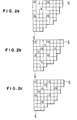
- the control rod operation pattern shown in Fig. 2a has been set up beforehand on the basis of the rated output from the view point of long-term reactor core operation.
- the control rod operation pattern is shown only for a quarter of the reactor core, for the clarification of the drawings.
- the numerical values appearing in each frame represents the insertion depth in terms of 1/24 of the core height. Namely, numeral "24" represents the full insertion, while "0" or blank mans full withdrawal of the control rod.
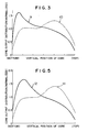
- the reactor core When the circulating pump is tripped under this control rod operation pattern, the reactor core is made to operate along the natural circulation curve 5 in Fig. 1. In such a case, the output distribution has a large peak in the lower core portion as shown by a curve 9 in Fig. 3.
- the core flow rate and the core heat output are about 23% and about 47% under this condition, respectively.
- the decay ratio is 0.85.
- the decay ratio represents the nuclear-hydrothermally stability of the nuclear reactor, that is, indicates how quickly the output returns the ordinary state after a disturbance such as a pressure change occurs.
- the decay ratio can be generally defined as a ratio of an amplitude of the second wave of the output fluctuation to an amplitude of the first wave thereof.
- Fig. 2b shows the control rod operation pattern after the control in accordance with the invention.
- This control rod pattern is realized by effecting a control rod operation shown in Fig. 2c on the control rod operation pattern shown in Fig. 2a, when the core flow rate has come down below 45% of the rated core flow rate while the core heat output has been increased beyond 62% of the rated output under 45% core flow rate.
- the positive and negative symbols show, respectively, the driving of the control rods to greater and smaller depths.
- the output distribution shows a peak value of 1.30 at the height of 16/24 of the core height, as will be seen from curve 10 in Fig. 3.
- the core flow rate is about 23% while the core heat output is about 47% so that the decay ratio is decreased to 0.61 which is about 28% improvement as compared with that attained before the execution of control shown in Fig. 2c.
- the control rod operation pattern is determined in accordance with a rule to minimize the amount of operation of the control rods.
- the control is made in such a way that the control rods which have been inserted to the depth greater than 13/24 still remain within the range of insertion depth not smaller than 13/24 even after the operation, and the control rods which have been fully withdrawn remains at small insertion depth not greater than 12/24 of the core height, whereby the control rod operation is facilitated considerably. It is advisable that the control rods obliquely neighbouring the control rods which have been inserted to large depth are selected as the control rods which are to be inserted newly from the fully withdrawn position.
- the amount of operation of the control rods may be determined as follows, although it may be calculated beforehand by off-line computation.
- the newly inserted control rods are inserted to a depth of 3/24 of the core height thereby to reduce the level of the heat output in the lower core portion.
- the control rods which have been inserted to a large depth are withdrawn to a depth of about 14/24 to further decrease the level of the output in the lower core portion.
- the amount of insertion of the control rods is adjusted by the operator while observing the output distribution through a core performance observation system so as not to allow the formation of large peak in the lower core portion.
- the level of the heat output under low core flow rate in the control rod operation pattern shown in Fig. 2b, attained by the operation control of the invention is substantially equal to the heat output level obtained with the pattern shown in Fig. 2a before the operation control.
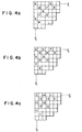
- Fig. 4a shows a control rod operation pattern which has been determined beforehand from the view point of long-term operation of the reactor core.
- the power distribution along the natural circulation line (core heat output 49%, c :e flow rate 26%) in this control rod operation pattern has a peak value of 1.68 at a position located at a level 5/24 of the core height from the bottom of the core. In this state, the decay ratio takes a value of 0.68.
- Fig. 4b shows the control rod operation pattern attained after the operation control in accordance with the invention. This control rod operation pattern is obtained by effecting a control as shown in Fig. 4c on the pattern shown in Fig.
- the core heat output is about 60% and the core flow rate is about 26% of the rated values.
- the power distribution has a peak value of 1.40 at a position located at the level of 17/24 of the core height from the bottom of the core.
- the decay ratio in this state takes a value of 0.48 which amounts to about 21% improvement as compared with that in the state shown in Fig. 4a.
- the difference between the first and second embodiments resides in the control rod operation pattern which is determined from the view point of long-term operation of the reactor core. Namely, in the first embodiment explained in connection with Fig. 2a, only the control rods which have been inserted to large depth are used in the operation control, whereas, in the second embodiment explained in connection with Fig. 4a, both of the control rods inserted to large depth and control rods inserted to small depth take part in the operation control. It will be understood, however, that the control of the operation is conducted by employing the aforementioned methods (1) and (2) in either embodiment.
- the predicted core flow rate and core heat output at which the control rod operation in accordance with the controlling method of the invention is commenced vary depending on the nature of the nuclear reactor, and can be determined by various suitable ways. For instance, it is possible to determine the core flow rate and core heat output such that the decay ratio is converged around 0.5, through an off-line stability analysis.
Landscapes
- Physics & Mathematics (AREA)
- Engineering & Computer Science (AREA)
- Chemical & Material Sciences (AREA)
- Chemical Kinetics & Catalysis (AREA)
- Plasma & Fusion (AREA)
- General Engineering & Computer Science (AREA)
- High Energy & Nuclear Physics (AREA)
- Monitoring And Testing Of Nuclear Reactors (AREA)
- Physical Or Chemical Processes And Apparatus (AREA)
Applications Claiming Priority (2)
| Application Number | Priority Date | Filing Date | Title |
|---|---|---|---|
| JP57155044A JPS5944689A (ja) | 1982-09-06 | 1982-09-06 | 沸騰水型原子炉の運転制御方法 |
| JP155044/82 | 1982-09-06 |
Publications (3)
| Publication Number | Publication Date |
|---|---|
| EP0103249A2 true EP0103249A2 (fr) | 1984-03-21 |
| EP0103249A3 EP0103249A3 (en) | 1984-12-12 |
| EP0103249B1 EP0103249B1 (fr) | 1987-04-08 |
Family
ID=15597439
Family Applications (1)
| Application Number | Title | Priority Date | Filing Date |
|---|---|---|---|
| EP83108729A Expired EP0103249B1 (fr) | 1982-09-06 | 1983-09-05 | Procédé de conduite d'un réacteur à eau bouillante |
Country Status (4)
| Country | Link |
|---|---|
| US (1) | US4632803A (fr) |
| EP (1) | EP0103249B1 (fr) |
| JP (1) | JPS5944689A (fr) |
| DE (1) | DE3370893D1 (fr) |
Cited By (2)
| Publication number | Priority date | Publication date | Assignee | Title |
|---|---|---|---|---|
| WO1996016411A1 (fr) * | 1994-11-23 | 1996-05-30 | Siemens Aktiengesellschaft | Systeme et procede d'arret rapide d'un reacteur nucleaire |
| RU2179755C1 (ru) * | 2000-08-15 | 2002-02-20 | Государственное унитарное предприятие Государственный научный центр РФ - Физико-энергетический институт им. академика А.И. Лейпунского | Канал для циклирования нагрузки твэлов |
Families Citing this family (2)
| Publication number | Priority date | Publication date | Assignee | Title |
|---|---|---|---|---|
| US6697447B1 (en) * | 1999-12-30 | 2004-02-24 | General Electric Company | Maximum extended load line limit analysis for a boiling water nuclear reactor |
| JP5553966B2 (ja) | 2008-03-19 | 2014-07-23 | 千代田化工建設株式会社 | 水銀吸着材およびその吸着材を用いた排煙処理方法 |
Family Cites Families (12)
| Publication number | Priority date | Publication date | Assignee | Title |
|---|---|---|---|---|
| US3565760A (en) * | 1967-10-23 | 1971-02-23 | Gen Electric | Nuclear reactor power monitor system |
| BE760096A (fr) * | 1970-02-19 | 1971-05-17 | Siemens Ag | Procede de reglage de la puissance de reacteurs nucleaires a eau sous pression |
| JPS6139636B2 (fr) * | 1974-07-15 | 1986-09-04 | Hitachi Ltd | |
| US4129475A (en) * | 1975-07-31 | 1978-12-12 | Westinghouse Electric Corp. | Method of operating a nuclear reactor |
| GB1521615A (en) * | 1976-04-13 | 1978-08-16 | Atomic Energy Authority Uk | Nuclear reactor control |
| US4075059A (en) * | 1976-04-28 | 1978-02-21 | Combustion Engineering, Inc. | Reactor power reduction system and method |
| US4279698A (en) * | 1977-01-25 | 1981-07-21 | Hitachi, Ltd. | Nuclear reactor operation control process |
| JPS5435595A (en) * | 1977-08-25 | 1979-03-15 | Toshiba Corp | Water boller reactor |
| JPS5435591A (en) * | 1977-08-26 | 1979-03-15 | Hitachi Ltd | Reactor operating system |
| JPS5435594A (en) * | 1977-08-26 | 1979-03-15 | Hitachi Ltd | Operational system of reactor |
| US4285769A (en) * | 1978-10-19 | 1981-08-25 | General Electric Company | Control cell nuclear reactor core |
| FR2493582A1 (fr) * | 1980-11-03 | 1982-05-07 | Framatome Sa | Procede de conduite d'un reacteur nucleaire par deplacement, dans le coeur de ce reacteur, de groupes de barres de commande |
-
1982
- 1982-09-06 JP JP57155044A patent/JPS5944689A/ja active Granted
-
1983
- 1983-09-05 EP EP83108729A patent/EP0103249B1/fr not_active Expired
- 1983-09-05 DE DE8383108729T patent/DE3370893D1/de not_active Expired
- 1983-09-06 US US06/529,760 patent/US4632803A/en not_active Expired - Lifetime
Cited By (3)
| Publication number | Priority date | Publication date | Assignee | Title |
|---|---|---|---|---|
| WO1996016411A1 (fr) * | 1994-11-23 | 1996-05-30 | Siemens Aktiengesellschaft | Systeme et procede d'arret rapide d'un reacteur nucleaire |
| US5854817A (en) * | 1994-11-23 | 1998-12-29 | Siemens Aktiengesellscaft | Fast shutdown system and process for fast shutdown of a nuclear reactor |
| RU2179755C1 (ru) * | 2000-08-15 | 2002-02-20 | Государственное унитарное предприятие Государственный научный центр РФ - Физико-энергетический институт им. академика А.И. Лейпунского | Канал для циклирования нагрузки твэлов |
Also Published As
| Publication number | Publication date |
|---|---|
| JPS5944689A (ja) | 1984-03-13 |
| EP0103249A3 (en) | 1984-12-12 |
| JPH0353591B2 (fr) | 1991-08-15 |
| EP0103249B1 (fr) | 1987-04-08 |
| DE3370893D1 (en) | 1987-05-14 |
| US4632803A (en) | 1986-12-30 |
Similar Documents
| Publication | Publication Date | Title |
|---|---|---|
| US4337118A (en) | Nuclear reactor power monitoring system | |
| EP0406637A2 (fr) | Installation d'un réacteur à eau bouillante à réduction diphasique de suppression de pression | |
| US4632803A (en) | Operating method of boiling water reactor | |
| KR101224605B1 (ko) | 원자로의 출력 및 축방향 출력분포 제어방법 | |
| JP3053226B2 (ja) | 選択制御棒挿入方法 | |
| JP3011451B2 (ja) | 沸騰水型原子力プラントの炉出力制御装置 | |
| KR102900926B1 (ko) | 원자로 부하 추종 운전 시스템 | |
| US4386048A (en) | Variable overlap control | |
| JP2868894B2 (ja) | 原子力発電所の監視方法 | |
| Pushkarev et al. | Ways of altering the coefficients of reactivity in RBMK reactors | |
| JP3117207B2 (ja) | 沸騰水型原子炉用燃料集合体 | |
| JPH0631819B2 (ja) | 原子力発電所の負荷追従運転方法 | |
| JPS6318151B2 (fr) | ||
| JPS58155396A (ja) | 沸騰水形原子力発電所の負荷追従運転方法 | |
| JPS61117486A (ja) | 原子炉核熱水力安定性制御装置 | |
| JPH04235386A (ja) | 原子炉の運転方法 | |
| JPH07128489A (ja) | 沸騰水型原子炉の運転方法 | |
| JPH0894784A (ja) | Gem装置 | |
| JPH04258791A (ja) | 原子炉出力制御方法及びその装置 | |
| JPH021276B2 (fr) | ||
| JPH0445796B2 (fr) | ||
| JPH06258474A (ja) | 沸騰水型原子炉 | |
| JPS6357757B2 (fr) | ||
| JPH0241714B2 (fr) | ||
| Ake et al. | Fuel Cycle Extension by Part-Length Control Rod Removal at Rancho Seco |
Legal Events
| Date | Code | Title | Description |
|---|---|---|---|
| PUAI | Public reference made under article 153(3) epc to a published international application that has entered the european phase |
Free format text: ORIGINAL CODE: 0009012 |
|
| AK | Designated contracting states |
Designated state(s): DE GB SE |
|
| PUAL | Search report despatched |
Free format text: ORIGINAL CODE: 0009013 |
|
| AK | Designated contracting states |
Designated state(s): DE GB SE |
|
| 17P | Request for examination filed |
Effective date: 19841213 |
|
| GRAA | (expected) grant |
Free format text: ORIGINAL CODE: 0009210 |
|
| AK | Designated contracting states |
Kind code of ref document: B1 Designated state(s): DE GB SE |
|
| REF | Corresponds to: |
Ref document number: 3370893 Country of ref document: DE Date of ref document: 19870514 |
|
| PLBE | No opposition filed within time limit |
Free format text: ORIGINAL CODE: 0009261 |
|
| STAA | Information on the status of an ep patent application or granted ep patent |
Free format text: STATUS: NO OPPOSITION FILED WITHIN TIME LIMIT |
|
| 26N | No opposition filed | ||
| GBPC | Gb: european patent ceased through non-payment of renewal fee | ||
| PG25 | Lapsed in a contracting state [announced via postgrant information from national office to epo] |
Ref country code: GB Free format text: LAPSE BECAUSE OF NON-PAYMENT OF DUE FEES Effective date: 19881122 |
|
| EAL | Se: european patent in force in sweden |
Ref document number: 83108729.1 |
|
| PGFP | Annual fee paid to national office [announced via postgrant information from national office to epo] |
Ref country code: SE Payment date: 19990621 Year of fee payment: 17 |
|
| PGFP | Annual fee paid to national office [announced via postgrant information from national office to epo] |
Ref country code: DE Payment date: 19990930 Year of fee payment: 17 |
|
| PG25 | Lapsed in a contracting state [announced via postgrant information from national office to epo] |
Ref country code: SE Free format text: THE PATENT HAS BEEN ANNULLED BY A DECISION OF A NATIONAL AUTHORITY Effective date: 20000929 |
|
| EUG | Se: european patent has lapsed |
Ref document number: 83108729.1 |
|
| PG25 | Lapsed in a contracting state [announced via postgrant information from national office to epo] |
Ref country code: DE Free format text: LAPSE BECAUSE OF NON-PAYMENT OF DUE FEES Effective date: 20010601 |