EP0103283A2 - Vorrichtung zum Vortreiben eines Werkzeuges in den Boden unter kontinuierlicher Drehbewegung - Google Patents
Vorrichtung zum Vortreiben eines Werkzeuges in den Boden unter kontinuierlicher Drehbewegung Download PDFInfo
- Publication number
- EP0103283A2 EP0103283A2 EP83108909A EP83108909A EP0103283A2 EP 0103283 A2 EP0103283 A2 EP 0103283A2 EP 83108909 A EP83108909 A EP 83108909A EP 83108909 A EP83108909 A EP 83108909A EP 0103283 A2 EP0103283 A2 EP 0103283A2
- Authority
- EP
- European Patent Office
- Prior art keywords
- tube
- hollow
- rotating
- implement
- jack
- Prior art date
- Legal status (The legal status is an assumption and is not a legal conclusion. Google has not performed a legal analysis and makes no representation as to the accuracy of the status listed.)
- Granted
Links
Images

Classifications
-
- E—FIXED CONSTRUCTIONS
- E21—EARTH OR ROCK DRILLING; MINING
- E21B—EARTH OR ROCK DRILLING; OBTAINING OIL, GAS, WATER, SOLUBLE OR MELTABLE MATERIALS OR A SLURRY OF MINERALS FROM WELLS
- E21B3/00—Rotary drilling
- E21B3/02—Surface drives for rotary drilling
-
- E—FIXED CONSTRUCTIONS
- E02—HYDRAULIC ENGINEERING; FOUNDATIONS; SOIL SHIFTING
- E02D—FOUNDATIONS; EXCAVATIONS; EMBANKMENTS; UNDERGROUND OR UNDERWATER STRUCTURES
- E02D7/00—Methods or apparatus for placing sheet pile bulkheads, piles, mouldpipes, or other moulds
- E02D7/22—Placing by screwing down
-
- E—FIXED CONSTRUCTIONS
- E02—HYDRAULIC ENGINEERING; FOUNDATIONS; SOIL SHIFTING
- E02D—FOUNDATIONS; EXCAVATIONS; EMBANKMENTS; UNDERGROUND OR UNDERWATER STRUCTURES
- E02D7/00—Methods or apparatus for placing sheet pile bulkheads, piles, mouldpipes, or other moulds
- E02D7/26—Placing by using several means simultaneously
-
- E—FIXED CONSTRUCTIONS
- E21—EARTH OR ROCK DRILLING; MINING
- E21B—EARTH OR ROCK DRILLING; OBTAINING OIL, GAS, WATER, SOLUBLE OR MELTABLE MATERIALS OR A SLURRY OF MINERALS FROM WELLS
- E21B7/00—Special methods or apparatus for drilling
- E21B7/20—Driving or forcing casings or pipes into boreholes, e.g. sinking; Simultaneously drilling and casing boreholes
Definitions
- This invention relates to devices for insertion of rotating tools into the ground.
- Such tools are normally mounted at the end of a tube.
- the word "tube” will be used herainafter for indicating any elongate drilling means which may be caused to penetrate into the ground.
- the jaw grip also controlled by three jacks, may occur any time at a different position, not exactly coincident with the axis of the device controlling the tool advancement and rotation. This could cause the distortion of the tool carrier tube and inaccuracies in hole execution.
- This device of the prior art allows only the use of drilling devices for which the rotation can be discontinuously imparted; for example, use cannot be made of tricones, diamonded tools for the drilling of rocks or alluvial grounds, etc.
- a further advantageous improvement consists in mounting the jaws as a pendulum with the suspension point integral with the sleeve.
- the gripping jaws are interchangeable to accomodate different tube diameters.
- a further improvement of the invention provides that the actuating head is fitted with a floating sleeve, so that the tube advancement can for sane length be independent of the advancement of the rotating head.
- the threads normally provided at each end of the tube lengths are not damaged during the lead-in step.
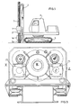
- the inventive apparatus comprises an actuating head 1 mounted on a column 3 carried by a structure 4 movable on tracks, wheels or sliding blocks 5.
- Said actuating head 1 is vertically driven along the column 3 by known means provided on the column, which applies axial forces relative to tube T and directed in both directions. That is forces serving both to drive the tube T into the ground and withdraw it.
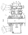
- the actuating head 1 performs the function of causing the hollow central shaft 15 and sleeve 16 integral therewith to rotate by means of two hydraulic motors 23 (Fig. 4).
- the vice 2 is provided integral with the sleeve 16. Its function is that of selectively gripping and disengaging the tube T. Both said head 1 and vice 2 are hollow, so as to allow the passage therethrough of said tube T which projects below and above thereto. After the tube has been gripped, said head 1 and vice 2 move downward. When the positions 1a and 2a, shown by broken lines in Fig. 1, are reached respectively by vice and head, said vice releases the tube T and moves upward along the tube to grip it again at the position shown by full line.
- each hydraulic motor 23 can be connected to both the pinion 41 and gear 42 by means of the clutch 49.
- Said pinion 41 and gear 42 respectively mesh with the gear wheels 43 and 44 integral with the shaft 45, on which the pinion 46 is also mounted. The latter drives the wheel 47 integral with the hollow shaft 15.
- Said hollow shaft 15 is slidably connected to a sleeve 16 which is integral for rotation with the shaft 15, but axially free.
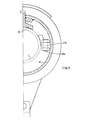
- the sleeve 16 has an integral flange 16a, to which the flange 37a of said vice 2 is bolted (Figgs. 2 and 3).
- the vice 2 has a ring 37 coaxial with the hollow shaft 15.
- Said ring 37 has a flange 37a which is made integral with the flange 16a.
- Said ring 37 is provided with ears 37b, each of which having a rod 48 pivoted thereto by a pin 48a.
- the movable jaws 33 are secured by screws 36 to the end of rods 48, so that such jaws are pendulum mounted. Thus, they can be readily replaced by other jaws of different sizes, such as to acccmodate tubes T of different diameters.
- each jaw 33 has a sloping surface 33a cooperating with the sloping surface 27a of a plate 27 mounted on a collar 26 providing for radially displacing said jaw 33 whenever said collar is axially moved. Said jaw 33 is held at opening position by springs 30.
- the axial movement carried out by the collar 26 is imparted to the latter by a hollow jack 50 which does not rotate.
- the jack 50 is supported by the ring 37 through the two thrust bearings 21 and bushing 28 and is arranged concentrically to the ring 37 and sleeve 16. It consists of a hollow piston 29 and jacket 38.
- the piston 29 is axially secured to the ring 37 by screws 29a and flat bushing 39 penetrating into a notch 39a integral with said piston 29.
- the jacket 38 is axially movable together with the collar 26 which does not rotate. This is provided with a notch 26, in which the flat bushing 59 slides.
- Bushing 49 is integral with said jacket 38 by the screw 24.
Landscapes
- Engineering & Computer Science (AREA)
- Mining & Mineral Resources (AREA)
- Life Sciences & Earth Sciences (AREA)
- Geology (AREA)
- General Life Sciences & Earth Sciences (AREA)
- Environmental & Geological Engineering (AREA)
- Fluid Mechanics (AREA)
- Physics & Mathematics (AREA)
- Geochemistry & Mineralogy (AREA)
- Mechanical Engineering (AREA)
- Paleontology (AREA)
- Civil Engineering (AREA)
- General Engineering & Computer Science (AREA)
- Structural Engineering (AREA)
- Earth Drilling (AREA)
- Road Repair (AREA)
- Turning (AREA)
Priority Applications (1)
| Application Number | Priority Date | Filing Date | Title |
|---|---|---|---|
| AT83108909T ATE35564T1 (de) | 1982-09-13 | 1983-09-09 | Vorrichtung zum vortreiben eines werkzeuges in den boden unter kontinuierlicher drehbewegung. |
Applications Claiming Priority (2)
| Application Number | Priority Date | Filing Date | Title |
|---|---|---|---|
| IT23221/82A IT1190999B (it) | 1982-09-13 | 1982-09-13 | Procedimento atto a migliorare l'esecuzione di perforazioni mediante l'inserimento di utensili nel terreno e relativa apparecchiatura |
| IT2322182 | 1982-09-13 |
Publications (3)
| Publication Number | Publication Date |
|---|---|
| EP0103283A2 true EP0103283A2 (de) | 1984-03-21 |
| EP0103283A3 EP0103283A3 (en) | 1984-09-26 |
| EP0103283B1 EP0103283B1 (de) | 1988-07-06 |
Family
ID=11205037
Family Applications (1)
| Application Number | Title | Priority Date | Filing Date |
|---|---|---|---|
| EP83108909A Expired EP0103283B1 (de) | 1982-09-13 | 1983-09-09 | Vorrichtung zum Vortreiben eines Werkzeuges in den Boden unter kontinuierlicher Drehbewegung |
Country Status (4)
| Country | Link |
|---|---|
| EP (1) | EP0103283B1 (de) |
| AT (1) | ATE35564T1 (de) |
| DE (1) | DE3377290D1 (de) |
| IT (1) | IT1190999B (de) |
Cited By (4)
| Publication number | Priority date | Publication date | Assignee | Title |
|---|---|---|---|---|
| EP1660729A4 (de) * | 2003-07-24 | 2008-07-09 | Yip Hoi Thong | Rammvorrichtung |
| US20150016893A1 (en) * | 2013-07-05 | 2015-01-15 | American Piledriving Equipment, Inc | Accessory connection systems and methods for use with helical piledriving systems |
| JP2016223237A (ja) * | 2015-06-03 | 2016-12-28 | ジャパンパイル株式会社 | 鋼管杭埋設方法、及び、鋼管杭埋設システム |
| US10995563B2 (en) | 2017-01-18 | 2021-05-04 | Minex Crc Ltd | Rotary drill head for coiled tubing drilling apparatus |
Families Citing this family (2)
| Publication number | Priority date | Publication date | Assignee | Title |
|---|---|---|---|---|
| CN102112685A (zh) | 2008-07-31 | 2011-06-29 | Yk设备私人有限公司 | 打桩装置 |
| US9249551B1 (en) | 2012-11-30 | 2016-02-02 | American Piledriving Equipment, Inc. | Concrete sheet pile clamp assemblies and methods and pile driving systems for concrete sheet piles |
Family Cites Families (7)
| Publication number | Priority date | Publication date | Assignee | Title |
|---|---|---|---|---|
| FR1083891A (fr) * | 1953-07-24 | 1955-01-13 | Bade & Co Gmbh | Procédé de tubage et dispositif pour sa mise en oeuvre |
| GB1094201A (en) * | 1964-09-16 | 1967-12-06 | Cementation Co Ltd | Improvements in rotary ground boring apparatus |
| FR1524223A (fr) * | 1967-03-22 | 1968-05-10 | Presspali Spa | Procédé et dispositif pour la manoeuvre d'un mécanisme à mouvement alternatif rotatif pour l'enfoncement et l'enlèvement du sol de poteaux, tubes de forage et similaires |
| BE755680A (fr) * | 1969-09-11 | 1971-02-15 | Allard Pierre J M T | Dispositif de serrage et de manoeuvre d'un tube de forage, pieude fondation ou analogue |
| JPS5117204B2 (de) * | 1971-11-08 | 1976-06-01 | ||
| DE2438956A1 (de) * | 1974-08-14 | 1976-02-26 | Leffer Stahl & App | Hydraulische verrohrungsmaschine |
| GB2114185B (en) * | 1982-01-25 | 1985-05-01 | Matsuzawa Kiko Kk | Method for boring vertical hole and machine therefor |
-
1982
- 1982-09-13 IT IT23221/82A patent/IT1190999B/it active
-
1983
- 1983-09-09 DE DE8383108909T patent/DE3377290D1/de not_active Expired
- 1983-09-09 AT AT83108909T patent/ATE35564T1/de not_active IP Right Cessation
- 1983-09-09 EP EP83108909A patent/EP0103283B1/de not_active Expired
Cited By (7)
| Publication number | Priority date | Publication date | Assignee | Title |
|---|---|---|---|---|
| EP1660729A4 (de) * | 2003-07-24 | 2008-07-09 | Yip Hoi Thong | Rammvorrichtung |
| US7591612B2 (en) | 2003-07-24 | 2009-09-22 | Yk Equipment Pte Ltd. | Piling device |
| US20150016893A1 (en) * | 2013-07-05 | 2015-01-15 | American Piledriving Equipment, Inc | Accessory connection systems and methods for use with helical piledriving systems |
| US9371624B2 (en) * | 2013-07-05 | 2016-06-21 | American Piledriving Equipment, Inc. | Accessory connection systems and methods for use with helical piledriving systems |
| JP2016223237A (ja) * | 2015-06-03 | 2016-12-28 | ジャパンパイル株式会社 | 鋼管杭埋設方法、及び、鋼管杭埋設システム |
| US10995563B2 (en) | 2017-01-18 | 2021-05-04 | Minex Crc Ltd | Rotary drill head for coiled tubing drilling apparatus |
| US11136837B2 (en) | 2017-01-18 | 2021-10-05 | Minex Crc Ltd | Mobile coiled tubing drilling apparatus |
Also Published As
| Publication number | Publication date |
|---|---|
| EP0103283A3 (en) | 1984-09-26 |
| DE3377290D1 (en) | 1988-08-11 |
| IT8223221A0 (it) | 1982-09-13 |
| EP0103283B1 (de) | 1988-07-06 |
| IT8223221A1 (it) | 1984-03-13 |
| ATE35564T1 (de) | 1988-07-15 |
| IT1190999B (it) | 1988-02-24 |
Similar Documents
| Publication | Publication Date | Title |
|---|---|---|
| US4526242A (en) | Drilling device | |
| US3741322A (en) | Drilling rig with drill rod magazine | |
| US3926267A (en) | Device for driving holes in the ground | |
| US4102409A (en) | Rock drilling machine | |
| EP0103283B1 (de) | Vorrichtung zum Vortreiben eines Werkzeuges in den Boden unter kontinuierlicher Drehbewegung | |
| US4711310A (en) | Rotary head | |
| US5033554A (en) | Well point placement and removal apparatus | |
| US3301334A (en) | Drill rig | |
| US3737245A (en) | Drill bit for pole boring machine | |
| JPH11500501A (ja) | 掘削及びパイプ埋立装置 | |
| EP0312724B1 (de) | Verfahren und Vorrichtung zum Herstellen von Bohrlöchern im Boden | |
| US4147457A (en) | Method and an apparatus for driving sheet piles into the ground | |
| SE429149B (sv) | Maskin for senkborrning i berg | |
| US3738765A (en) | Sealing structure for pole boring machine | |
| EP0310679B1 (de) | Vorrichtung zum bohren im bereich der anschlussstelle eines ausgekleideten rohres | |
| US20070044592A1 (en) | Apparatus for handling tubulars and method | |
| JPS6135356B2 (de) | ||
| US4721171A (en) | Opening device for drill rods for an extension rod drilling equipment | |
| JP3015733B2 (ja) | 横穴掘削装置 | |
| SE415586B (sv) | Anordning for nergrevning av en pa sjobottnen utlagd rorledning | |
| GB2053053A (en) | An over-the-top drilling rig with a combined bitching and coupling unit | |
| SU631639A1 (ru) | Механизм привода кулачкового зажима шнека | |
| HU212887B (en) | Apparatus and method for cutting-up the internal surface of piping | |
| JP2567334Y2 (ja) | 調査兼用ボーリングマシン | |
| CN210359362U (zh) | 多尺寸轴承套圈斜油孔加工装置 |
Legal Events
| Date | Code | Title | Description |
|---|---|---|---|
| PUAI | Public reference made under article 153(3) epc to a published international application that has entered the european phase |
Free format text: ORIGINAL CODE: 0009012 |
|
| AK | Designated contracting states |
Designated state(s): AT CH DE FR GB IT LI NL |
|
| PUAL | Search report despatched |
Free format text: ORIGINAL CODE: 0009013 |
|
| AK | Designated contracting states |
Designated state(s): AT CH DE FR GB IT LI NL |
|
| 17P | Request for examination filed |
Effective date: 19850502 |
|
| 17Q | First examination report despatched |
Effective date: 19860212 |
|
| GRAA | (expected) grant |
Free format text: ORIGINAL CODE: 0009210 |
|
| AK | Designated contracting states |
Kind code of ref document: B1 Designated state(s): AT CH DE FR GB IT LI NL |
|
| PG25 | Lapsed in a contracting state [announced via postgrant information from national office to epo] |
Ref country code: NL Effective date: 19880706 Ref country code: LI Effective date: 19880706 Ref country code: FR Free format text: THE PATENT HAS BEEN ANNULLED BY A DECISION OF A NATIONAL AUTHORITY Effective date: 19880706 Ref country code: CH Effective date: 19880706 Ref country code: AT Effective date: 19880706 |
|
| REF | Corresponds to: |
Ref document number: 35564 Country of ref document: AT Date of ref document: 19880715 Kind code of ref document: T |
|
| ITF | It: translation for a ep patent filed | ||
| REF | Corresponds to: |
Ref document number: 3377290 Country of ref document: DE Date of ref document: 19880811 |
|
| PG25 | Lapsed in a contracting state [announced via postgrant information from national office to epo] |
Ref country code: GB Effective date: 19880909 |
|
| REG | Reference to a national code |
Ref country code: CH Ref legal event code: PL |
|
| EN | Fr: translation not filed | ||
| NLV1 | Nl: lapsed or annulled due to failure to fulfill the requirements of art. 29p and 29m of the patents act | ||
| PLBE | No opposition filed within time limit |
Free format text: ORIGINAL CODE: 0009261 |
|
| STAA | Information on the status of an ep patent application or granted ep patent |
Free format text: STATUS: NO OPPOSITION FILED WITHIN TIME LIMIT |
|
| GBPC | Gb: european patent ceased through non-payment of renewal fee | ||
| PG25 | Lapsed in a contracting state [announced via postgrant information from national office to epo] |
Ref country code: DE Effective date: 19890601 |
|
| 26N | No opposition filed | ||
| ITTA | It: last paid annual fee |