EP0103301A2 - Dispositif optique à grand angle - Google Patents
Dispositif optique à grand angle Download PDFInfo
- Publication number
- EP0103301A2 EP0103301A2 EP83109036A EP83109036A EP0103301A2 EP 0103301 A2 EP0103301 A2 EP 0103301A2 EP 83109036 A EP83109036 A EP 83109036A EP 83109036 A EP83109036 A EP 83109036A EP 0103301 A2 EP0103301 A2 EP 0103301A2
- Authority
- EP
- European Patent Office
- Prior art keywords
- ring
- lens
- optical
- ring lens
- image
- Prior art date
- Legal status (The legal status is an assumption and is not a legal conclusion. Google has not performed a legal analysis and makes no representation as to the accuracy of the status listed.)
- Granted
Links
- 230000003287 optical effect Effects 0.000 title claims abstract description 68
- 230000005540 biological transmission Effects 0.000 claims abstract description 6
- 238000012937 correction Methods 0.000 description 12
- 238000000034 method Methods 0.000 description 5
- 239000005331 crown glasses (windows) Substances 0.000 description 3
- 238000012360 testing method Methods 0.000 description 3
- 238000004026 adhesive bonding Methods 0.000 description 2
- 238000013459 approach Methods 0.000 description 2
- 230000008859 change Effects 0.000 description 2
- 238000010276 construction Methods 0.000 description 2
- 238000013461 design Methods 0.000 description 2
- 230000009466 transformation Effects 0.000 description 2
- 239000000853 adhesive Substances 0.000 description 1
- 230000001070 adhesive effect Effects 0.000 description 1
- 235000015278 beef Nutrition 0.000 description 1
- 230000008901 benefit Effects 0.000 description 1
- 230000001427 coherent effect Effects 0.000 description 1
- 230000008878 coupling Effects 0.000 description 1
- 238000010168 coupling process Methods 0.000 description 1
- 238000005859 coupling reaction Methods 0.000 description 1
- 238000011161 development Methods 0.000 description 1
- 230000000694 effects Effects 0.000 description 1
- 238000005265 energy consumption Methods 0.000 description 1
- 238000005516 engineering process Methods 0.000 description 1
- 239000000463 material Substances 0.000 description 1
- 239000002184 metal Substances 0.000 description 1
- 230000035515 penetration Effects 0.000 description 1
- 230000008569 process Effects 0.000 description 1
Images


Classifications
-
- G—PHYSICS
- G03—PHOTOGRAPHY; CINEMATOGRAPHY; ANALOGOUS TECHNIQUES USING WAVES OTHER THAN OPTICAL WAVES; ELECTROGRAPHY; HOLOGRAPHY
- G03B—APPARATUS OR ARRANGEMENTS FOR TAKING PHOTOGRAPHS OR FOR PROJECTING OR VIEWING THEM; APPARATUS OR ARRANGEMENTS EMPLOYING ANALOGOUS TECHNIQUES USING WAVES OTHER THAN OPTICAL WAVES; ACCESSORIES THEREFOR
- G03B37/00—Panoramic or wide-screen photography; Photographing extended surfaces, e.g. for surveying; Photographing internal surfaces, e.g. of pipe
- G03B37/06—Panoramic or wide-screen photography; Photographing extended surfaces, e.g. for surveying; Photographing internal surfaces, e.g. of pipe involving anamorphosis
-
- G—PHYSICS
- G02—OPTICS
- G02B—OPTICAL ELEMENTS, SYSTEMS OR APPARATUS
- G02B13/00—Optical objectives specially designed for the purposes specified below
- G02B13/06—Panoramic objectives; So-called "sky lenses" including panoramic objectives having reflecting surfaces
-
- G—PHYSICS
- G03—PHOTOGRAPHY; CINEMATOGRAPHY; ANALOGOUS TECHNIQUES USING WAVES OTHER THAN OPTICAL WAVES; ELECTROGRAPHY; HOLOGRAPHY
- G03B—APPARATUS OR ARRANGEMENTS FOR TAKING PHOTOGRAPHS OR FOR PROJECTING OR VIEWING THEM; APPARATUS OR ARRANGEMENTS EMPLOYING ANALOGOUS TECHNIQUES USING WAVES OTHER THAN OPTICAL WAVES; ACCESSORIES THEREFOR
- G03B17/00—Details of cameras or camera bodies; Accessories therefor
- G03B17/56—Accessories
- G03B17/565—Optical accessories, e.g. converters for close-up photography, tele-convertors, wide-angle convertors
Definitions
- the invention relates to a wide-angle optical device which can be connected to known optical or photographic devices for recording and projecting round images.
- the horizontal viewing angle of the lenses of the photographic apparatus used to photograph the natural and artificial surroundings is between 5 ° and 180 °, the latter also being called fish-eye optics.
- the range of lenses with a viewing angle of 180 ° to 360 ° is missing.
- a lens with a horizontal viewing angle of 360 ° would be suitable to record the surroundings next to and behind the apparatus on a single image in addition to the surroundings in front of the recording apparatus and the positive single image reproduced by reversing the beam path on a circular screen.
- the recording is made with eleven cameras on eleven films at the same time and the projection requires eleven pieces of synchronously controlled projectors.
- the image format of the individual images is a standardized rectangle with an aspect ratio of 1: 1.33; the circular screen is therefore a poligonal prism.
- the projected images are separated by black stripes.
- the projector assigned to the opposite screen is arranged behind this black image column. This process is known under the name "CYRKORAMA" and was first introduced in the United States pavilion at the World Exposition in sheep by projecting cinema films.
- the aim of the invention was to create a wide-angle optical device that can be used as an optical approach for any photo-technical apparatus, for example, Cameras, film cameras, FS cameras, telescopes are suitable for generating a complete or partially complete circular image recording, or making any projector or image monitor suitable for the projection of complete or partially complete circular images.
- the essence of the invention is that the surface points of an object cylinder jacket can be translated into a plane if the object image on the cylinder jacket is mapped onto a cone surface arranged in the cylinder interior by rays directed towards the center of the cylinder and perpendicular to the cylinder jacket and then the object points on the Conical surface is transmitted by central projection in an image plane perpendicular to the common longitudinal axis of the cylinder and the conical surface.
- This device has been further developed according to the invention in such a way that it has a housing which can preferably be detachably connected to the lens of an optical or photo-technical device, has a ring lens fastened in the housing and a cover plate coupled to the ring lens, the outer circumferential surface of the ring lens being formed as a light transmission surface, and furthermore the ring lens has a narrowing opening in the direction of the lens, the surface surface of which, seen from the light transmission surface, is designed as a mirror surface is, and the optical axis of the housing and the ring lens coincides with the optical axis of the lens of the optical or photographic device.
- the housing is an opaque cylinder which has an external thread at its lens end.
- the device according to the invention can be coupled as an approach to any commercially available optical or photographic device.
- the outer surface of the optical opening of the ring lens is a truncated cone surface with an angle of 45 ° to the horizontal plane of the ring lens.
- the distortion-free operability of the device depends to a large extent on it,
- the outer surface of the optical opening of the ring lens is a toroidal surface, the tangent of which, with the frustoconical surface which can be used in its place, forms an angle of at most 3 ° in the crossing points.
- the outer jacket of the ring lens can be a cylinder jacket parallel to the optical axis of the ring lens, or a concave circular arc shaped jacket or convex arcuate jacket.
- a further optical ring is arranged so as to be freely movable around the ring lens.
- This ring can be a ring with a rectangular cross section, or a plano-concave ring, or a plano-convex ring, or a double-concave ring or a double-convex ring.
- a finder prism is arranged on the outside of the cover plate and a correction lens on the inside of the cover plate coaxial to the ring lens.
- the finder prism makes it easier to find the selected main subject and the correction lens serves to eliminate the difference in the object width of the ring lens and the finder prism.
- the use of the device according to the invention is significantly facilitated if the finder prism is arranged on the cover plate so as to be freely rotatable about its optical axis.
- a cuboid or cylindrical prism attachment of a base plate and a front plate of the finder prism is connected, the rear side of which, forming an angle of 45 ° to the optical axis, is designed as a mirror surface as seen from the front plate.
- the front plate of the finder prism can be a concave or convex cylinder jacket with a longitudinal axis which is transverse or parallel to the optical axis of the ring lens, or a concave or convex spherical surface with a radius perpendicular to the optical axis of the ring lens.
- the correction lens is a plano-convex converging lens or plano-concave scattering lens.
- the optical means used in the device according to the invention can be made from crown glass or from corresponding optical plastic.
- the various configurations of the jacket of the ring lens in the device according to the invention serve to change the vertical viewing angle and to interchange the edges of the object cylinder.
- part of the jacket of the object cylinder is depicted as the main motif.
- the viewfinder prism By focusing the viewfinder prism, the intersection of the object cylinder jacket and the horizontal plane, i.e. the panorama is in focus.
- the circular image of the respective object cylinder is shown in the form of a ring image in the film plane of the optical or photo-technical device due to the transformation of the ring lens in the device according to the invention.
- the focus is adjusted with the distance adjustment element of the device after the viewfinder prism has been aimed at the main subject of the object cylinder jacket.
- the image of the main motif is in the middle of the beef image and can be shrunk in one or both directions.
- the up or down Components of the object cylinder appear in the ring pattern, depending on the design of the ring lens, as radii directed towards the center of the ring pattern or outwards from the center.
- Internal data such as exposure time, aperture, distance and possible leveling can be stored in the empty corners of the individual image.
- the image in the center of the ring image of the main motif depicted by the viewfinder prism can be represented as a conventional image.
- the beam path of the device according to the invention is to be reversed during the projection.
- the conventional projector should be provided with a device according to the invention which does not contain a finder prism.
- the ring image on the single image creates a complete, coherent and real spatial effect during the projection on a circular screen.
- the image of the main motif can be emitted.
- a single film camera is required for the recording, and a single film projector - provided with the device according to the invention - is also to be used for the reproduction.
- the wide-angle optical device according to the invention is also suitable for testing self-vibrations of building structures, by attaching tuning forks of known vibrations close to the horizontal plane and flickering stripes on the construction elements of the building.
- the image color valency is proportional to the number of vibrations, so the ideal number of self-vibrations and the dynamic factor can be determined by interpolation and adjusted by changing the span and mass accordingly.
- a vibration graphic can also be recorded by stationary rotation of the recording device equipped with the device according to the invention about the optical axis.
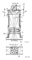
- a ring lens 1 made of crown glass or optical plastic has a cylindrical outer shell 2 according to its basic shape.
- An optical opening 3 is formed concentrically in the interior of the ring lens 1, so that the ring lens 1 has a frusto-conical inner jacket 7 which forms an angle of 45 ° with the vertical and which is designed as an optical mirror surface.
- the opening 3 is delimited at the top by a base circle 4 and at the bottom by a tip circle 6 closer to a camera 5.
- the section through the ring lens 1 shows that it is composed of a rectangle 8 and a right-angled, isosceles triangle 9.
- the diameter of the tip circle 6 is one third of the diameter of the ring lens 1.
- the concentric opening 3 in the interior of the ring lens 1 is designed such that its jacket 7 has a toroidal surface instead of a truncated cone shape, the jacket 7 with a guide curve to the base circle 4 and is adapted to the tip circle 6, and the tangent of the surface encloses an angle of at most 3 ° with the stub cone surface that can be used in its place in the crossing point.
- FIGS. 3-7 show the ring lens 1 according to the invention with a cylindrical jacket 2 and various additional optical rings 11. The ring lens 1 and the respective additional optical ring 11 are clamped together.
- the ring lens 1 is fastened to an edge 13 of a housing 12 by gluing.
- the housing 12 is an opaque metal cylinder which, at its end opposite the ring lens 1, has an external thread similar to the light filters available on the market. This male thread ensures the simple, detachable and secure coupling of the device according to the invention and the respective optical or photographic device.
- the housing 12 ensures that the optical axes of the ring lens 1 and an objective 14 of the camera 5 match.
- the end face of the ring lens 1 is covered with a cover plate 15 fastened by adhesive and opaque. This cover plate 15 prevents the direct or indirect penetration of undesired stray rays through the ring lens 1 into the housing 12 or into the lens 14.
- a finder prism 17 is adapted in a sleeve 16 arranged concentrically on the cover plate 15.
- the cross section of the finder prism 17 is the same as the simple main section of the ring lens 1.
- a cuboid prism attachment 20, 21 is attached to a base plate 18 and a front plate 19, and a rear side 22 of the finder Prism 17 forms an angle of 45 ° to its optical axis, the rear side 22 being designed as a mirror surface as seen from the front plate 19.
- the rear side 22 of the finder prism 17 can also be replaced by a plane mirror.
- a plano-convex converging lens is fixed coaxially by gluing as a correction lens 23.
- the task of the correction lens 23 is to compensate for the difference in the object width between the ring lens 1 and the finder prism 17.
- FIG. 10 shows a single image which was exposed with a camera 5 provided with the device according to the invention.
- the light rays project the object cylinder points from the jacket of the object cylinder 25 lying in a set object width t of the camera 5 in a reduced and distorted manner on the reflective jacket 7 of the ring lens 1, and the lens 14 of the camera 5 transforms these light beams onto the film 24 in such a way that a center circle 28 of a ring image 27 in the film plane corresponds to a section circle of the object cylinder 25 and a horizon plane h, the pixels in the ring image 27 thicken outwards from the center circle 28 and condense from the center circle 28 towards the center.
- the conventional distance adjuster 14 serves to change the beam length of the object cylinder 25.
- the image of the object plane selected by the finder prism 17 lies in the middle of the individual image in the film 25, the image points shrinking in one or in both mutually perpendicular directions or shrinking centrally are.
- FIG. 11 shows an embodiment of the wide-angle optical device according to the invention, in which an annular lens 1 with a frusto-conical inner jacket 7 and cylindrical outer jacket 2 is fastened to the housing 12.
- a plano-concave optical ring 11 is connected to the jacket 2 of the ring lens 1, accordingly a prism attachment 20 with a concave cylindrical jacket and with a longitudinal axis of the front plate 19 of the finder prism 17 perpendicular to the optical axis of the ring lens 1 is adapted.
- a plano-convex converging lens is glued to the underside of the cover plate 15 as a correction lens 23.
- the direction of the component of the object cylinder 25 in the case of the ring lens 1 with a concave circular-arc-shaped jacket 2 corresponds to the beam path of the ring lens 1 with a cylindrical jacket 2.
- FIG. 25 A single image exposed with the device shown above is visible in FIG.
- the image of the jacket of the object cylinder 25 appears as a ring image 27 on the film 24, an inner concentric circle 29 delimiting the ring image 27 with the image of the tip circle 6 of the ring lens 1, ie with the image of the base circle of the object cylinder 25, and another the concentric circle 30 delimiting the ring pattern 27 with the image of the base circle 4 of the ring lens 1, ie with the image of the roof circle of the object cylinder 25 is the same.
- the upward direction of the component of the object cylinder 25 corresponds to that from the center pointing outwards in the ring pattern 27 as well as in the ring lens 1 with a cylindrical jacket 2.
- the outer circle 30 touches the sides of the frame on the film 24.
- the object width t des Objectives 14 can be adjusted so that the outer circle 30 touches the corners of the single image on the film 24.
- various internal data such as exposure time, aperture, distance and possible leveling, can be recorded in the empty corners of the individual image.
- a ring lens 1 with a frustoconical jacket 7, and with a cylindrical jacket 2 supplemented with a plano-convex optical ring 11, a finder prism 17 with a convex spherical front plate 19 and a plano-concave scattering lens are arranged as a correction lens 23.
- FIG. 14 A single image exposed with the device described above is visible in FIG. 14.
- the direction of the component of the object cylinder 25 is reversed by 180 ° by the ring lens 1 having a convex outer jacket 2 in the form of a circular arc, compared with the beam path of the ring lens 1 with a concave circular or cylindrical jacket 2.
- the upward direction of the component of the object cylinder 25 corresponds to a direction pointing to the center in the ring image 27.
- That transmitted through the finder prism 17 Image lies in the plane of the object cylinder 25, so that a flat image 31 located in the center of the single image can be focused by focusing the viewfinder image.
- the flat image 31 can be used to record the main motif independently of the ring image 27.
- the arrows drawn with a continuous line in the figures represent the upward-pointing component of the object cylinder 25 and their illustrations on the single image.
- the arrows drawn with dashed lines represent the straight line of the object plane of the viewfinder prism image and its image on the individual image.
- the image produced by the camera supplemented with the device according to the invention can be displayed on a circular screen or a circular photographic paper as a circular image with a projector consisting of a light source, a parabolic mirror and a converging lens.
- the projection distance, the ratio of the height and the circumference of the circular image can be changed by correcting the focal point and the beam length of the focal length.
- the flat image 31 can be projected through the finder prism 17 onto a screen or photo paper.
- the ring lens 1 is also covered on its jacket 2 and the projected image has a normal size or a panorama size depending on the front plate design of the finder prism 17.
- the device according to the invention can be connected to cameras, film cameras, FS cameras, video cameras, to optical instruments and devices and to image projectors.
- the device can be used to test self-vibrations of three-dimensional building structures. Flickering strips are to be glued to one side of the critical building structure vibrating in a plane perpendicular to the horizontal plane, and tuning forks of known vibration numbers are to be arranged parallel to the vibration level in the vicinity of the point of maximum deflection.
- the finder prism is aimed at the tuning fork and at the same time this and the building structure are vibrated. After the round image has been recorded, the image color valence of the vibrating elements in the ring image 27 and in the flat image 31 changes in connection with the number of vibrations.
- the number of vibrations of the tuning fork can be compared with the number of vibrations of the component and the number of self-vibrations of the building structure and the components connected to it can be determined by interpolation. Knowing the self-vibration number, the ideal self-vibration number or the dynamic factor of the construction can be set by changing the span and the cash register.
Landscapes
- Physics & Mathematics (AREA)
- General Physics & Mathematics (AREA)
- Optics & Photonics (AREA)
- Lenses (AREA)
- Optical Radar Systems And Details Thereof (AREA)
- Stereoscopic And Panoramic Photography (AREA)
- Accessories Of Cameras (AREA)
Priority Applications (1)
| Application Number | Priority Date | Filing Date | Title |
|---|---|---|---|
| AT83109036T ATE24780T1 (de) | 1982-09-14 | 1983-09-13 | Weitwinkelige optische vorrichtung. |
Applications Claiming Priority (2)
| Application Number | Priority Date | Filing Date | Title |
|---|---|---|---|
| HU292182 | 1982-09-14 | ||
| HU822921A HU193030B (en) | 1982-09-14 | 1982-09-14 | Optical instrument of wide visual angle |
Publications (3)
| Publication Number | Publication Date |
|---|---|
| EP0103301A2 true EP0103301A2 (fr) | 1984-03-21 |
| EP0103301A3 EP0103301A3 (en) | 1984-09-05 |
| EP0103301B1 EP0103301B1 (fr) | 1987-01-07 |
Family
ID=10961687
Family Applications (1)
| Application Number | Title | Priority Date | Filing Date |
|---|---|---|---|
| EP83109036A Expired EP0103301B1 (fr) | 1982-09-14 | 1983-09-13 | Dispositif optique à grand angle |
Country Status (7)
| Country | Link |
|---|---|
| EP (1) | EP0103301B1 (fr) |
| JP (1) | JPS59140442A (fr) |
| AT (1) | ATE24780T1 (fr) |
| CS (1) | CS250234B2 (fr) |
| DD (1) | DD214221A5 (fr) |
| DE (1) | DE3369010D1 (fr) |
| HU (1) | HU193030B (fr) |
Cited By (7)
| Publication number | Priority date | Publication date | Assignee | Title |
|---|---|---|---|---|
| US4900914A (en) * | 1987-05-27 | 1990-02-13 | Carl-Zeiss-Stiftung | Wide-angle viewing window with a plurality of optical structures |
| EP0671613A1 (fr) * | 1994-03-09 | 1995-09-13 | TEMIC TELEFUNKEN microelectronic GmbH | Système optique |
| EP0816891A1 (fr) * | 1996-06-27 | 1998-01-07 | HE HOLDINGS, INC. dba HUGHES ELECTRONICS | Système intégré de détection optique panoramique et à haute résolution |
| EP0766112A3 (fr) * | 1995-09-26 | 1998-04-01 | Rockwell International Corporation | Assemblé optique panoramique avec élément d'entrée réfléchissant plan |
| US6082869A (en) * | 1999-04-01 | 2000-07-04 | Draheim; Jon M | Door/window mounted safety mirror |
| US7034999B1 (en) | 1998-09-29 | 2006-04-25 | Casler Christopher L | Hemispheric lens for a remote-controlled retail electronic entertainment device |
| EP1440562A4 (fr) * | 2001-09-18 | 2009-05-06 | Wave Group Ltd | Systeme d'imagerie panoramique a zoom optique |
Families Citing this family (5)
| Publication number | Priority date | Publication date | Assignee | Title |
|---|---|---|---|---|
| JPH02151828A (ja) * | 1988-12-02 | 1990-06-11 | Mitsubishi Electric Corp | 全方位観測装置 |
| US4973113A (en) * | 1989-04-20 | 1990-11-27 | E. I. Du Pont De Nemours And Company | Method and apparatus for making transmission holograms |
| TW198748B (fr) * | 1990-02-20 | 1993-01-21 | Hughes Aircraft Co | |
| DE102010041490A1 (de) * | 2010-09-27 | 2012-03-29 | Carl Zeiss Microimaging Gmbh | Optisches Instrument und Verfahren zur optischen Überwachung |
| DE102012215624B3 (de) * | 2012-09-04 | 2014-02-27 | FoxyLED GmbH | Optische Anordnung |
Family Cites Families (4)
| Publication number | Priority date | Publication date | Assignee | Title |
|---|---|---|---|---|
| FR338386A (fr) * | 1903-03-21 | 1904-05-17 | Francois Fernand Bourdil | Système de production d'images panoramiques animées |
| US2304434A (en) * | 1928-09-03 | 1942-12-08 | Ibm | Projecting device |
| GB1026870A (en) * | 1963-06-06 | 1966-04-20 | Akinwunmi Adegboye | Improvements in or relating to panoramic cine cameras |
| GB1493188A (en) * | 1975-04-22 | 1977-11-23 | Anderson H | Optic for instantaneously photographing an horizon of 360 degree |
-
1982
- 1982-09-14 HU HU822921A patent/HU193030B/hu not_active IP Right Cessation
-
1983
- 1983-09-13 DE DE8383109036T patent/DE3369010D1/de not_active Expired
- 1983-09-13 EP EP83109036A patent/EP0103301B1/fr not_active Expired
- 1983-09-13 AT AT83109036T patent/ATE24780T1/de not_active IP Right Cessation
- 1983-09-14 JP JP58168495A patent/JPS59140442A/ja active Pending
- 1983-09-14 DD DD83254824A patent/DD214221A5/de unknown
- 1983-09-14 CS CS836696A patent/CS250234B2/cs unknown
Cited By (7)
| Publication number | Priority date | Publication date | Assignee | Title |
|---|---|---|---|---|
| US4900914A (en) * | 1987-05-27 | 1990-02-13 | Carl-Zeiss-Stiftung | Wide-angle viewing window with a plurality of optical structures |
| EP0671613A1 (fr) * | 1994-03-09 | 1995-09-13 | TEMIC TELEFUNKEN microelectronic GmbH | Système optique |
| EP0766112A3 (fr) * | 1995-09-26 | 1998-04-01 | Rockwell International Corporation | Assemblé optique panoramique avec élément d'entrée réfléchissant plan |
| EP0816891A1 (fr) * | 1996-06-27 | 1998-01-07 | HE HOLDINGS, INC. dba HUGHES ELECTRONICS | Système intégré de détection optique panoramique et à haute résolution |
| US7034999B1 (en) | 1998-09-29 | 2006-04-25 | Casler Christopher L | Hemispheric lens for a remote-controlled retail electronic entertainment device |
| US6082869A (en) * | 1999-04-01 | 2000-07-04 | Draheim; Jon M | Door/window mounted safety mirror |
| EP1440562A4 (fr) * | 2001-09-18 | 2009-05-06 | Wave Group Ltd | Systeme d'imagerie panoramique a zoom optique |
Also Published As
| Publication number | Publication date |
|---|---|
| CS250234B2 (en) | 1987-04-16 |
| ATE24780T1 (de) | 1987-01-15 |
| EP0103301B1 (fr) | 1987-01-07 |
| DD214221A5 (de) | 1984-10-03 |
| EP0103301A3 (en) | 1984-09-05 |
| HU193030B (en) | 1987-08-28 |
| DE3369010D1 (en) | 1987-02-12 |
| JPS59140442A (ja) | 1984-08-11 |
Similar Documents
| Publication | Publication Date | Title |
|---|---|---|
| DE19832317C1 (de) | Anordnung, bei der von einer Lichtquelle aus Licht auf eine Fläche gerichtet wird | |
| DE69727052T2 (de) | Omnidirektionales bildaufnahmegerät | |
| DE19635666C1 (de) | Integriertes Mikroskop | |
| DE19851000C2 (de) | Projektionsanordnung | |
| DE602004003305T2 (de) | Bildprojektor | |
| DE3020171C2 (de) | Suchervorrichtung für eine Fernsehkamera | |
| EP0103301B1 (fr) | Dispositif optique à grand angle | |
| DE2645187C2 (de) | Fernsehkamera | |
| DE2602967A1 (de) | Verfahren zur aufnahme oder projektion einer panorama-ansicht und vorrichtung zur ausfuehrung desselben | |
| DE2240746A1 (de) | Optisches abbildungsgeraet | |
| DE2611971A1 (de) | Optische vorrichtung zum uebertragen von licht oder zum betrachten eines bildes | |
| EP1464164A1 (fr) | Unite camera video | |
| DE1937933A1 (de) | Optischer Wandler zum Umwandeln einer perspektivischen Photographie eines kugelfoermigen Koerpers in eine ebene Projektion | |
| EP1754106B1 (fr) | Dispositif de surimposition d'informations dans la trajectoire du faisceau du viseur d'une camera | |
| DE19907345A1 (de) | Vorrichtung zum Abbilden eines als Raster von Bildpunkten darstellbaren Bildes auf einem Schirm | |
| DE2217156A1 (de) | Verfahren zur aufzeichnung und wiedergabe von bildern | |
| DE677812C (de) | Verfahren und Vorrichtung zur Kinematographie mittels Linsenraster | |
| EP0285907B1 (fr) | Dispositif de copie électophotographique | |
| DE3823075A1 (de) | Verfahren und vorrichtung zur einstellung einer abbildung einer vorlage auf eine bildflaeche einer bildaufnahmeroehre oder dergleichen | |
| DE1814693C (de) | Spiegelreflex-Kamera mit rnikrophotometrischer Kontrolle | |
| DE2316273C3 (de) | Verfahren und Vorrichtung zur Kontrastminderung bei der Reproduktion | |
| AT223465B (de) | Einäugige Spiegelreflexkamera | |
| DE1597409C (de) | Farbfernsehkamera | |
| DE60310563T2 (de) | Verbesserungen an einem Bildprojektor | |
| DE616298C (de) | Photographische Kamera mit Einstellsucher |
Legal Events
| Date | Code | Title | Description |
|---|---|---|---|
| PUAI | Public reference made under article 153(3) epc to a published international application that has entered the european phase |
Free format text: ORIGINAL CODE: 0009012 |
|
| AK | Designated contracting states |
Designated state(s): AT BE CH DE FR GB IT LI LU NL SE |
|
| PUAL | Search report despatched |
Free format text: ORIGINAL CODE: 0009013 |
|
| AK | Designated contracting states |
Designated state(s): AT BE CH DE FR GB IT LI LU NL SE |
|
| 17P | Request for examination filed |
Effective date: 19840928 |
|
| GRAA | (expected) grant |
Free format text: ORIGINAL CODE: 0009210 |
|
| AK | Designated contracting states |
Kind code of ref document: B1 Designated state(s): AT BE CH DE FR GB IT LI LU NL SE |
|
| PG25 | Lapsed in a contracting state [announced via postgrant information from national office to epo] |
Ref country code: NL Effective date: 19870107 Ref country code: IT Free format text: LAPSE BECAUSE OF FAILURE TO SUBMIT A TRANSLATION OF THE DESCRIPTION OR TO PAY THE FEE WITHIN THE PRESCRIBED TIME-LIMIT;WARNING: LAPSES OF ITALIAN PATENTS WITH EFFECTIVE DATE BEFORE 2007 MAY HAVE OCCURRED AT ANY TIME BEFORE 2007. THE CORRECT EFFECTIVE DATE MAY BE DIFFERENT FROM THE ONE RECORDED. Effective date: 19870107 |
|
| REF | Corresponds to: |
Ref document number: 24780 Country of ref document: AT Date of ref document: 19870115 Kind code of ref document: T |
|
| REF | Corresponds to: |
Ref document number: 3369010 Country of ref document: DE Date of ref document: 19870212 |
|
| ET | Fr: translation filed | ||
| NLV1 | Nl: lapsed or annulled due to failure to fulfill the requirements of art. 29p and 29m of the patents act | ||
| PG25 | Lapsed in a contracting state [announced via postgrant information from national office to epo] |
Ref country code: LU Free format text: LAPSE BECAUSE OF NON-PAYMENT OF DUE FEES Effective date: 19870930 |
|
| PLBE | No opposition filed within time limit |
Free format text: ORIGINAL CODE: 0009261 |
|
| STAA | Information on the status of an ep patent application or granted ep patent |
Free format text: STATUS: NO OPPOSITION FILED WITHIN TIME LIMIT |
|
| 26N | No opposition filed | ||
| PG25 | Lapsed in a contracting state [announced via postgrant information from national office to epo] |
Ref country code: GB Effective date: 19880913 Ref country code: AT Effective date: 19880913 |
|
| PG25 | Lapsed in a contracting state [announced via postgrant information from national office to epo] |
Ref country code: SE Effective date: 19880914 |
|
| PG25 | Lapsed in a contracting state [announced via postgrant information from national office to epo] |
Ref country code: LI Effective date: 19880930 Ref country code: CH Effective date: 19880930 Ref country code: BE Effective date: 19880930 |
|
| BERE | Be: lapsed |
Owner name: KOZPONTI VALTO-ES HITELBANK RC Effective date: 19880930 |
|
| PG25 | Lapsed in a contracting state [announced via postgrant information from national office to epo] |
Ref country code: FR Free format text: LAPSE BECAUSE OF NON-PAYMENT OF DUE FEES Effective date: 19890531 |
|
| REG | Reference to a national code |
Ref country code: CH Ref legal event code: PL |
|
| GBPC | Gb: european patent ceased through non-payment of renewal fee | ||
| PG25 | Lapsed in a contracting state [announced via postgrant information from national office to epo] |
Ref country code: DE Effective date: 19890601 |
|
| REG | Reference to a national code |
Ref country code: FR Ref legal event code: ST |
|
| EUG | Se: european patent has lapsed |
Ref document number: 83109036.0 Effective date: 19890712 |