EP0103310A2 - Dispositif de développement pour copieur électrostatique - Google Patents
Dispositif de développement pour copieur électrostatique Download PDFInfo
- Publication number
- EP0103310A2 EP0103310A2 EP83109210A EP83109210A EP0103310A2 EP 0103310 A2 EP0103310 A2 EP 0103310A2 EP 83109210 A EP83109210 A EP 83109210A EP 83109210 A EP83109210 A EP 83109210A EP 0103310 A2 EP0103310 A2 EP 0103310A2
- Authority
- EP
- European Patent Office
- Prior art keywords
- developing
- developing sleeve
- magnetic
- permanent magnet
- copying apparatus
- Prior art date
- Legal status (The legal status is an assumption and is not a legal conclusion. Google has not performed a legal analysis and makes no representation as to the accuracy of the status listed.)
- Granted
Links
Images




Classifications
-
- G—PHYSICS
- G03—PHOTOGRAPHY; CINEMATOGRAPHY; ANALOGOUS TECHNIQUES USING WAVES OTHER THAN OPTICAL WAVES; ELECTROGRAPHY; HOLOGRAPHY
- G03G—ELECTROGRAPHY; ELECTROPHOTOGRAPHY; MAGNETOGRAPHY
- G03G21/00—Arrangements not provided for by groups G03G13/00 - G03G19/00, e.g. cleaning, elimination of residual charge
- G03G21/0005—Arrangements not provided for by groups G03G13/00 - G03G19/00, e.g. cleaning, elimination of residual charge for removing solid developer or debris from the electrographic recording medium
- G03G21/0035—Arrangements not provided for by groups G03G13/00 - G03G19/00, e.g. cleaning, elimination of residual charge for removing solid developer or debris from the electrographic recording medium using a brush; Details of cleaning brushes, e.g. fibre density
-
- G—PHYSICS
- G03—PHOTOGRAPHY; CINEMATOGRAPHY; ANALOGOUS TECHNIQUES USING WAVES OTHER THAN OPTICAL WAVES; ELECTROGRAPHY; HOLOGRAPHY
- G03G—ELECTROGRAPHY; ELECTROPHOTOGRAPHY; MAGNETOGRAPHY
- G03G15/00—Apparatus for electrographic processes using a charge pattern
- G03G15/06—Apparatus for electrographic processes using a charge pattern for developing
- G03G15/08—Apparatus for electrographic processes using a charge pattern for developing using a solid developer, e.g. powder developer
- G03G15/09—Apparatus for electrographic processes using a charge pattern for developing using a solid developer, e.g. powder developer using magnetic brush
Definitions
- the present invention generally relates to a developing device for a transfer type electrostatic copying apparatus.
- the invention relates to a developing device which is so arranged that, by supplying mono-component magnetizable toner onto a developing sleeve which is driven for rotation, magnetic brush is formed on the developing sleeve by the action of a stationary permanent magnet provided within said developing sleeve, while the bristle length of the magnetic brush is restricted by a bristle cutting member.
- the developing apparatus which is arranged to form the magnetic brush by supplying the mono-component magnetizable toner onto the peripheral surface of the developing sleeve to be rotated around a stationary permanent magnet
- the surplus mono-component magnetizable toner of the magnetic brush cut off by the bristle cutting member for restricting the bristle length tends to stay stationarily at the upstream side of the bristle cutting member along the rotational direction of the developing sleeve, thereby to cause the mono-component magnetizable toner to be solidified, and thus, an undesirable blocking phenomenon is liable to take place.
- the mono-component magnetizable toner is blocked by the solidified mono-component magnetizable toner and cannot be transported up to the developing position, thus making it impossible to effect the developing.
- the remaining mono-component magnetizable toner which has not been used for the development at the developing position is continuously rotated as it is attracted onto the predetermined position of the developing sleeve, thereby to be magnetized by the powerful magnetizing action from the permanent magnet, with corresponding reduction of fluidity of the mono-component magnetizable toner.
- an object of the invention is to provide an improved developing apparatus for use in an electrostatic copying apparatus which is capable of preventing the blocking phenomenon of the mono-component magnetizable toner by a bristle cutting member, and also capable of maintaining the proper fluidity of the mono-component magnetizable toner and also uniformity in the state of formation of the brush bristles of the magnetic brush, through solution of the technical problems as described above.
- another object of the invention is to provide an improved developing device capable of preventing the blockina of the developing material within the storaqe container, and also capable of supplying the developing material to the develo p inq roller by approximately a predetermined amount through simple construction, with substantial elimination of the technical problems inherent in the prior art arrangements as described above.
- the invention still further relates in its preferred form to a presence detection device of a developing material in the developing device for use in an electrostatic copying apparatus and more particularly, to a presence detection device of the developing material in the developing device arranged to form magnetic brush by supplying developing material onto the peripheral surface of a developing sleeve provided therein with a stationary permanent magnet and driven for rotation.
- another preferred object of the invention is to provide an inexpensive presence detection device with simple construction for use in a developing device of an electrostatic copying apparatus.
- an improved developing device for an electrostatic copying apparatus in which a permanent magnet having a plurality of magnetic poles magnetized at each equal space in a peripheral direction of the permanent magnet is coaxially secured in a hollow developing sleeve made of non-magnetic material and driven to rotate, a one-component magnetizable toner is supplied on the developing sleeve so as form a magnetic brush, and a bristle cutting member restricts a length of the magnetic brush, characterized in that there is provided a blade member made of non-magnetic material, disposed upstream along the rotational direction of the developing sleeve at the vicinity of the bristle cutting member, inclining to separate from the peripheral surface of the developing sleeve downstream along the rotational direction, and contacting with the peripheral surface of the developing sleeve.
- the neighboring magnetic poles are directed to have alternately opposite polar orientation, the magnetic poles formed at a magnetized position facing the bristle.cutting member and a magnetized position contacting with the blade member are neighboring and opposite polarization to each other, the blade member has a construction so as to allow the one-component magnetizable toner pass at about central position between the magnetic pole facing the bristle cutting member and the magnetic pole contacting with the blade member.
- the magnetized position contacting with the blade member has a pair of neighboring magnetic poles with the same polarization
- a single magnetized position of the permanent magnet has a pair of neighboring magnetic poles with the same polarization in an area from a developing zone to the blade member along the rotational direction of the developing sleeve.
- a plurality of magnetized positions of the permanent magnet has a pair of neighboring magnetic poles with the same polarization in an area from the developing zone to a blade member along the rotary direction of the developing direction.
- the blade member which is in sliding contact with the peripheral surface of the developing sleeve is provided at the upstream side immediately before the bristle cutting member along the rotational direction of the developing sleeve, the mono-component magnetizable toner is flowing at all times at the upstream side of the bristle cutting member, and accordingly, the undesirable blocking phenomenon of the mono-component magnetizable toner by the bristle cutting member may be advantageously prevented.
- the mono-component magnetizable toner on the developing sleeve is once separated from the peripheral surface of the developing sleeve by the blade member at every one rotation of the developing sleeve, the proper fluidity of the mono-component magnetizable toner can be positively achieved, with the state of bristle formation of the magnetic brush being uniformly maintained.
- the developing material is supplied onto a developing roller having the developing sleeve disposed in the vicinity of a photosensitive material, there are further provided, (f) a storage container having a bottom formed in an arcuate-shape and extending downwardly, and having a supply port opening for supply the developing material onto a peripheral surface of the developing roller, (g) a rotary shaft provided rotatably around the center of the arcuate bottom of the storage container, (h) a stirring and feeding means for stirring the developing material in the storage container to supply to the supply port, and extending radially from the rotary shaft to the vicinity of the inner surface of the bottom of the straqe container, ( i )a ratchet wheel secured to the rotary shaft axially, (j) a rocking lever having one end supported by a pin paralled to the rotary shaft, having the other end engaging to associate with the developing roller, and swingable around the pin in accordance with the rotational motion of the developing roller, and (k) a claw disposed on the immediate
- a presence-detecting device for detecting the developing material comprising; (1) a detecting member made of non-magnetic material, swingable about a horizontal axis in a vertical plane with respect to an axis of the developing sleeve between a first angular position corresponding to a substantially central position of neighborinq N pole and S pole of the permanent magnet at a vicinity of the developing sleeve in accordance with the depressing force of the maqnetizable toner attracted by the permanent magnet and a second angular position far from the developing sleeve in accordance with the own weight of the detectiong member against the depressing force of the developing material, disposed between the developing sleeve and an supply port of a developing material storaae container for storing the developing material and for supplying the developing material to the developing sleeve,(m) an engaging member swingable about a hprizontal axis formed integrally the detecting member, and (n) switching means having an actuator engaging with the engaging the engaging
- the developing material supplied from the storage container is depressed as it is attracted by the permanent magnet so that the detecting member is subjected to the angular displacement between the first angular displacement position and the second angular displacement position, with the switching state of the switch means being altered according to the angular displacement of said detecting member, and therefore, presence or absence of the developing material on the peripheral surface of the developing sleeve can be readily detected. Furthermore, at the first angular displacement position, since the detecting member is positioned at approximately the central portion between the N pole and S pole, said detecting member is readily subjected to the angular displacement even by the slight depressing force by the developing material.
- Fig. 1 a schematic side sectional view of a transfer type electrostatic copying machine according to one preferred embodiment of the invention.
- the copying apparatus of Fig. 1 includes a photosensitive or photoreceptor drum 4 having a photcsensitive material or photoreceptor 3 provided on the entire peripheral surface of a drum 2, and rotatably mounted at approximately a central portion of a machine housing 1.
- a charging corona discharger 6 for preliminarily charging the photoreceptor 3
- a developing device 7 for visualizing an electrostatic latent image formed on the photoreceptor 3 into a visible toner image
- a transfer corona discharger 8 for transferring the toner image thus formed on the photoreceptor 3 onto a copy paper sheet
- a cleaning device 9 for cleaning off the toner remaining on the photoreceptor 3 after the transfer process.
- an exposure device 10 for projecting light-wise image of an original to be copied (not shown) onto the photoreceptor 3 in a position between the charging corona discharger 6 and the developing device 7 as shown by the dotted arrows:
- an original carrier 11 is provided on which the original to be copied is horizontally placed for reciprocating movement as indicated by the arrows.
- a light projecting means 12 for projecting light onto the original through the original .carrier 11 further includes an exposure lamp 13, a reflector plate 14a and an auxiliary reflector plate 14b.
- the light projected towards the oriainal placed on the original carrier 11 is focussed onto the photoreceptor 3 through a single focal point lens 15 to form the image of the original thereon, and thus, the electrostatic latent image is formed on the photoreceptor 3.
- the copy paper sheets stacked and accommodated in a paper feeding cassette 17 are fed, one sheet by one sheet, by a paper feeding roller 18 from the paper feeding cassette 17.
- the copy paper sheets are transported by a pair of feeding and transporting rollers 21 and 22 through upper and lower guide plates 19 and 20 in pair.
- the copy paper sheet fed into a transfer region 25 through another pair of upper and lower guide plates 23 and 24 is caused to closely adhere to the surface of the photoreceptor drum 4 confronting the transfer corona charger 8.
- the copy paper sheet After the transfer process, the copy paper sheet is held, at its one edge in the direction of width thereof, between a separating roller 26 and an auxiliary separating roller 27 so as to be peeled off the surface of the photoreceptor drum 4, and is fed into a heat fixing device 31 having a pair of heat fixing rollers 29 and 30 through a guide plate 28. In this heat fixing device 31, the toner image on the surface of the copy paper sheet is fixed. After the fixing process as described above, the copy paper sheet is discharged onto a copy paper tray (not shown) through a pair of discharging rollers 32 and 33.
- a sprocket wheel 36 around which a first endless chain 37 is directed or passed.
- the chain 37 is sequentially passed around a sprocket wheel 38, a sprocket wheel 39 coupled to the feeding and transporting roller 22 and a sprocket wheel 40 connected to the copy paper feeding roller 18 along its running direction indicated by the.arrow.
- a second endless chain 41 is passed around another sprocket wheel (not shown) secured to the output shaft 35 so as to be one unit with the sprocket wheel 36.
- the chain 41 is sequentially passed around sprocket wheels 42 and 43, two sprocket wheels 44 and 45 for driving the original carrie--P 11, and sprocket wheels 46 and 47 along its running direction indicated by the arrow.
- the gear (not shown) to be rotated as one unit with the sprocket wheel 43 is engaged with a gear 48 connected to the heat fixing roller 29.
- the sprocket wheel 44 is connected to a gear 49 through a clutch which is not shown, while the sprocket wheel 45 is coupled to a gear 50 and a pulley 51 through a clutch which is not shown, with the gears 49 and 50 being in mesh with each other.
- a wire 160 connected, at its one end, to the right side end of the original carrier 11 in Fig.
- said original carrier 11 is driven by the driving force from the sprocket wheel 44, said original carrier 11 is caused to run at a comparatively high speed, while when the original carrier 11 is driven by the driving force from the sprocket wheel 45, it is caused to move at a comparatively low speed.
- a gear 52 mounted on the same shaft as the sprocket wheel 46 is connected to a gear 57 through gears 53, 54, 55 and 56.
- the gear 56 is secured to a rotary shaft 58 of the cleaning device 9, while the gear 57 is concentrically fixed to a sleeve 120 of the cleaning device 9.
- a gear 60 to be rotated as one unit with the sprocket wheel 47 is connected through a gear 61 to a gear 62 which is coupled to a cylindrical member 128 of the cleaning device 9. Meanwhile, the gear 60 is connected to a near 64 associated with the separating roller 26 through a gear 63.
- the gear 60 is connected to a gear 65 which is integral with the photoreceptor drum 4, while the gear 65 is engaged with a gear 69 through gears 66, 67 and 68, with the gear 69 being connected to a developing sleeve 71 of the developing device 7.
- the developina device 7 further includes a developing roller 72 disposed in the vicinity of the photoreceptor 3 in a direction parallel with the axis of the photoreceptor drum 4, a storage container 73 for storing therein the mono-component magnetizable toner, as a developing material, a stirring and feeding means 74 operably housed in the storage container 73 for stirring the mono-component magnetizable toner therein and also for supplying the mono-component magnetizable toner onto the developing roller 72, a bristle cutting member 75 for restricting the length of the magnetic brush bristles to be formed on the peripheral surface of the developing roller 72, and a blade member 76 for once separating the magnetic brush from the peripheral surface of the developing roller 72 so as to bring it towards the bristle cutting member 76.
- the developing roller 72 has a permanent magnet member 77 concentrically secured in the hollow developing sleeve 71 made of non-magnetizable material.
- One end of the permanent magnet member 77 extends through corresponding one end of the developing sleeve 71 through a bearing 82, and is fixed to a support member 81 secured to a front side plate 79 of a frame 78 of the developing device 7.
- the other end of the developing sleeve 71 extends through a rear side plate 80 of the frame 78 through a bearing 83, and is fixed with the qear 69.
- the other end of the permanent nacret member 77 is supported by the developing sleeve 71 through a bearing 84.
- the permanent magnet member 77 is magnetized by a plurality of magnetic poles circumferentially directed at equal intervals, with neighboring magnetic poles being directed to have alternately opposite polar orientation.
- the mono-component magnetizable toner supplied from the storage container 73 forms the magnetic brush on the developing sleeve 71.
- the peripheral surface of the photoreceptor 3 is rubbed against the magnetic brush, whereby the electrostatic latent image on the photoreceptor 3 is developed into the visible image.
- the storage container 73 includes an arcuate portion 87 having an arcuate shape in a vertical plane and extending in a direction parallel to the developing roller 72, and a conical portion 88 connected to the upper portion of the arcuate portion 87 at the side opposite to the developing roller 72 with respect to the central axis of the arcuate portion 87 and open upwardly as shown, and is formed into one unit with a frame 78.
- the arcuate portion 87 is formed with a supply port 89 for supplying the mono-component magnetizable toner onto the developing sleeve 72.
- the above supply port 89 is defined above the developing roller 72 so that the mono-component magnetizable toner may be supplied onto the peripheral surface of the developing roller 72.
- the stirring and supplyinq means 74 further includes a rotary shaft 92 journalled to the front and rear side plates 79 and 80 on the central axis of the arcuate portion 87 through bearings 90 and 91, a stirring and supplying member 93 integrally provided with the rotary shaft 92, a ratchet wheel 94 secured to one end of the rotary shaft 92, a rocking lever 96 pivotally supported at its end by a pin 95 provided on the rear side plate 80 and connected, at the other end thereof, to the gear 69 for rocking motion about said pin 95 following the rotation of the gear 69, a claw member 98 pivotally connected to an intermediate portion of the rocking lever 96 by a pin 97 for engagement with the teeth of the ratchet wheel 94, and a spring 99 which urges the claw member 98 towards the ratchet wheel 94.
- the stirrina and feedina member 93 extends in parallel with and adjacent to an inner wall 87a of the arcuate portion 87 between the front and rear side walls 79 and 80, with its opposite end portions being bent at right angles so as to be pressed into the rotary shaft 92 for securing.
- a pin 100 is provided, while an elongated opening 101 is formed at the other end of the rocking lever 96 for engagement with the pin 100.
- the spring 99 is provided to surround the pin 97, with one end of the spring 99 being engaged with the rocking lever 96 and the other end thereof, with the claw member 98. By the spring force of this spring 99, the claw member 98 is urged about the pin 97 in the direction shown by the arrow 102.
- the rocking lever 96 is provided with a stopper piece 103 for restricting the rotation of the claw member 98.
- the stirring and supply member 93 is rotated about the rotary shaft 92 following the rotational movement of the developing sleeve 71, whereby the mono-component magnetizable toner in the arcuate portion 87 is agitated, and is also brought to the supply port 89 through a longitudinal portion 93a of the stirring and supply member 93.
- the mono-component magnetizable toner thus brought to the supply port 89 is fed from said supply port 89 onto the peripheral surface of the developing sleeve 71.
- the number of revolutions of the stirring and supplying member 93 is so selected that the toner will not be absent on the peripheral surface of the developing sleeve 71, and in the embodiment described so far, it is arranged so that the stirring and supplying member 93 completes one rotation, while the developing sleeve 71 makes 30 rotations, which may be achieved by suitably selecting the number of teeth of the ratchet wheel 94 and rocking distance of the claw member 94.
- a reverse rotation preventing member 105 which is arranqed to contact with the teeth of the ratchet wheel 94 at the downstream side of the rotational direction 104.
- the magnetic brush on the developing sleeve 71 is always restricted to have a predetermined bristle length so as to be brought to the developing position 86, but at the upstream side immediately before the bristle cutting member 75, there may be a case where the mono-component magnetizable toner cut off by the bristle cutting member 75 remains to be solidified, thus giving rise to the so-called blocking phenomenon, which takes place due to depression of the mono-component magnetizable toner moving over the developing sleeve 71 by the bristle cutting member 75, and tends to occur more frequently as the force of the depression increases, i.e. as the number of planetuions of the developing sleeve 71 increases.
- the ma q netic bruch on the developing sleeve 71 is blocked by the mono-component magnetizable toner subjected to the blocking so as not to be fed to the developing position 86, thus making it impossible to effect the developing at the portion.
- the base portion of the magnetic brush does not contribute to the development, and remains on the peripheral surface of the developing sleeve 71 as it is so as to continue rotation together with the developing sleeve 71. Accordingly, the toner on the developing sleeve 71 is lowered in its fluidity, with alteration in the state of formation of the brush bristles, and thus, the developing efficiency is correspondingly reduced.
- the blade member 76 is provided at the upstream side of the bristle cutting member 75 along the rotational direction 85.
- the blade member 76 described above is so inclined as to be spaced from the developing sleeve 71 towards the downstream side along the rotational direction 85, with its base portion 76a being secured to the frame 78, and the free end 76b thereof is arranged to be slid on the developing sleeve 71 over its entire length.
- the position thereof corresponding to the bristle cuttina member 75 and the position which is in sliding contact with the free end 76b of the blade member 76 are magnetized by the neighboring magnetic poles having mutually different polar orientation.
- the position correspondinq to the bristle cutting member 75 is magnetized with the N pole, while the position corresponding to the blade member 76 is magnetized with S pole.
- a plurality of passing holes 106 are formed in the blade member 76 at a predetermined interval therebetween in the direction of width of said blade member 76 (i.e. in the direction perpendicular to the paper surface in Fig. 3). These passing holes 106 are each formed at approximately the central portion between the N pole (or S pole) corresponding to the bristle cutting member 75 and the S pole (or N pole) corresponding to the blade member 76.
- the passing holes 106 are each formed at approximately the central portion between the N pole and S pole as described earlier, the magnetic attracting force exerting on the mono-component magnetizable toner at the passing holes 106 is directed in a direction normal to the magnetic lines of force, i.e. in a radial inner direction of the developing sleeve 71. Accordingly, the toner is readily supplied towards the inner side of the radial direction of the developing sleeve 71 from the passing holes 106 through the above described magnetic attracting force.
- the mono-component magnetizable toner after being once separated from the peripheral surface of the developing sleeve 71, is caused to fall through the passing holes 106 to be fed onto the developing sleeve 71, and therefore, the toner is always fluidized immediately before the bristle cutting member 75, with the possibility of occurrence of the undesirable blocking being advantageously prevented.
- the mono-component magnetizable toner on the developing sleeve 71 is loosened or softened by the blade member 76 at every rotation of the developing sleeve 71, the bristles of the magnetic brush at the developing position 86 are formed in the same state at all times, with consequent improvements on the developing efficiency.
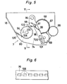
- Fig.7 showinq a simplified cross section taken along the line VII-VII in Fig. 3, the developing apparatus 7 is provided with a detecting device 110 for detecting the presence of the toner (refer to both Figs. 7 and 3).
- the detecting device 110 further includes a detecting member 111 extending vertically between the supply port 89 of the storage container 73 and the developing roller 72, and pivotable in a plane at right angles with respect to the axis of the developing roller 72, an engaging member 112 extending in parallel relation with respect to the axis of the developing roller 72 and rotatably supported by the side plates 79 and 80, and a microswitch 113 as a switching means whose switched state is varied in response to the angular displacement of the engaging member 112.
- the detecting member 111 extends vertically via a through-opening 114 defined in the frame 78 for restricting the range of angular displacement of said detecting member lll, while the engaging member 112 is disposed above the through-opening 114.
- One end portion of the engaging member 112 is bent at right angles at the outer side of the side plate 79, and the bent portion 112a thus formed is engaged with an actuator 115 of the microswitch 113, which is coupled, for example, to a toner replenishing instruction means such as a pilot lamp or the like (not shown).
- the detecting member 111 is rotated in the direction approaching the developing roller 72 through depression by the mono-component magnetizable toner as shown by the imaginary line in Fig. 3.
- the free end of the detecting member 111 corresponds to the approximately central position of the N pole and S pole of the permanent magnetic member 77, whereby the detecting member 111 comes to be readily subjected to the angular displacement through a slight depressing force by the mono-component magnetizable toner.
- the engaging member 112 is also subjected to the angular displacement, according to which the microswitch 113 is cut off. Accordingly, the pilot lamp as described earlier is kept de-energized at the first angular displacement position 116.
- the microswitch 113 is rendered conductive, with consequent illumination of the pilot lamp, and thus, it is indicated that the toner in the storage container 73 has been used up, with simultaneous absence of the toner on the peripheral surface of the developing sleeve 71.
- the detecting member 111 and engaging member 112 should preferably be made to be light in weight as far as practicable so that they may be subjected to the angular displacement even by the slight depressing force of the toner.
- FIG. 8 showing a cross sectional view of a developing apparatus according to another embodiment of the present invention, by which the developing apparatus 7 of the embodiment of Figs. 1 to 7 may be replaced.
- the permanent magnet member 77 is magnetized by a pair of magnetic poles (S poles in this embodiment) having the same polarity in a position corresponding to the position of sliding contact of the blade member 76 with the developing sleeve 71.
- S poles in this embodiment the magnetic poles are disposed at intervals of 2 to 6 mm on the circumferential surface of the permanent magnet member 77.
- the magnet member 77 is magnetized by the magnetic pole neighboring said two magnetic poles (S poles in this embodiment) and having polarity opposite thereto (N pole in this embodiment). Since other constructions of the developing device of Fig. 8 are generally similar to those of the arrangement of Fig 3, detailed description thereof is omitted here for brevity.
- the attracting force for attracting the mono-component magnetizable toner onto the developing sleeve 71 at the sliding contact position of the blade member 76 is weakened.
- the magnetic lines of force from the magnetic poles of the same polarity are directed in the radial direction of the developing sleeve 71, the mono-component magnetizable toner is subjected to the magnetic attracting force in the tangential direction of the developing sleeve 71.
- the mono-component magnetizable toner on the developing sleeve 71 is separated from the surface of the developing sleeve 71 at a position before the sliding contact position of the blade member 76, and jumps over the sliding contact position to be transferred to the blade member 76, and thus, reaches the passing holes 106. Accordingly, in the above arrangement, it is not necessary to cause the blade member 76 to strongly contact the sleeve 71, and therefore, the undesirable blocking of the toner by the blade member 76 can be prevented.
- FIG. 9 there is shown, on an enlaraed scale, a cross section of a developing apparatus according to a further embodiment of the invention, in which like parts corresponding to those in Fig. 3 are designated by like reference numerals.
- the permanent magnet member 77 is magnetized by a pair of magnetic poles having the same polarity (N poles in this embodiment) in the range from the developing position 86 to the blade member 76 along the rotational direction 85 of the developing sleeve 71.
- These magnetic poles are arranged, for example, at intervals of 2 to 6 mm on the circumferential surface of the permanent magnet member 77. Since other constructions are generally similar to those of the arrangement of Fig. 3, detail description thereof is also omitted here for brevity.
- the mono-component magnetizable toner of the magnetic brush formed on the surface of the developing sleeve 71 not contributing to the developing, and rotated together with the developing sleeve 71 from the developing position 86 is temporarily displaced when it passes the position at which said magnetic poles of the same polarity are disposed close to each other.
- the above displacement takes place because, in the region between the developing position 86 and the position at which said magnetic poles of the same polarity are disposed, the regular variation of the chain structure of the magnetic brush owing to the alternate arrangement of the N poles and S poles is shifted towards irregular variation.
- the mono-component magnetizable toner whose magnetizing function is thus weakened is transported up to the position of the blade member 76, the toner may be easily peeled off or scraped off from the peripheral surface of the developing sleeve 71.
- the position at which the pair of magnetic poles of the same polarity close to each other are to be magnetized is not limited to be one position as described in the above arrangement of Fig. 13, but may be further modified to be provided at a plurality of spots in the range from the developing position 86 to the blade member 76 along the rotational direction 85.
Landscapes
- Physics & Mathematics (AREA)
- General Physics & Mathematics (AREA)
- Dry Development In Electrophotography (AREA)
Priority Applications (1)
| Application Number | Priority Date | Filing Date | Title |
|---|---|---|---|
| EP19830109210 EP0103310B1 (fr) | 1980-01-31 | 1981-01-30 | Dispositif de développement pour copieur électrostatique |
Applications Claiming Priority (13)
| Application Number | Priority Date | Filing Date | Title |
|---|---|---|---|
| JP1181180A JPS56107274A (en) | 1980-01-31 | 1980-01-31 | Developing device of electrostatic copier |
| JP1980012034U JPS6328435Y2 (fr) | 1980-01-31 | 1980-01-31 | |
| JP11810/80 | 1980-01-31 | ||
| JP1980012036U JPS6328436Y2 (fr) | 1980-01-31 | 1980-01-31 | |
| JP12034/80U | 1980-01-31 | ||
| JP12036/80U | 1980-01-31 | ||
| JP1980012037U JPS6333225Y2 (fr) | 1980-01-31 | 1980-01-31 | |
| JP1203580U JPS56113346U (fr) | 1980-01-31 | 1980-01-31 | |
| JP12035/80U | 1980-01-31 | ||
| JP11811/80 | 1980-01-31 | ||
| JP1181080A JPS56107280A (en) | 1980-01-31 | 1980-01-31 | Cleaning device of transfer type electrostatic copier |
| JP12037/80U | 1980-01-31 | ||
| EP19830109210 EP0103310B1 (fr) | 1980-01-31 | 1981-01-30 | Dispositif de développement pour copieur électrostatique |
Related Parent Applications (2)
| Application Number | Title | Priority Date | Filing Date |
|---|---|---|---|
| EP19810300404 Division EP0033647B1 (fr) | 1980-01-31 | 1981-01-30 | Dispositif de nettoyage pour appareil de tirage électrostatique |
| EP19810300404 Division-Into EP0033647B1 (fr) | 1980-01-31 | 1981-01-30 | Dispositif de nettoyage pour appareil de tirage électrostatique |
Publications (3)
| Publication Number | Publication Date |
|---|---|
| EP0103310A2 true EP0103310A2 (fr) | 1984-03-21 |
| EP0103310A3 EP0103310A3 (en) | 1984-09-26 |
| EP0103310B1 EP0103310B1 (fr) | 1987-04-15 |
Family
ID=27561879
Family Applications (1)
| Application Number | Title | Priority Date | Filing Date |
|---|---|---|---|
| EP19830109210 Expired EP0103310B1 (fr) | 1980-01-31 | 1981-01-30 | Dispositif de développement pour copieur électrostatique |
Country Status (1)
| Country | Link |
|---|---|
| EP (1) | EP0103310B1 (fr) |
Family Cites Families (5)
| Publication number | Priority date | Publication date | Assignee | Title |
|---|---|---|---|---|
| JPS5843739B2 (ja) * | 1974-10-10 | 1983-09-28 | キヤノン株式会社 | 現像装置 |
| US3965862A (en) * | 1975-01-30 | 1976-06-29 | Xerox Corporation | Xerographic development system |
| JPS5451846A (en) * | 1977-09-30 | 1979-04-24 | Ricoh Co Ltd | Electrostatic latent image developing device |
| JPS54139548A (en) * | 1978-03-23 | 1979-10-30 | Hitachi Metals Ltd | Processor for magnetic toner |
| GB2046635B (en) * | 1979-02-15 | 1983-08-03 | Canon Kk | Magnet brush developer |
-
1981
- 1981-01-30 EP EP19830109210 patent/EP0103310B1/fr not_active Expired
Also Published As
| Publication number | Publication date |
|---|---|
| EP0103310B1 (fr) | 1987-04-15 |
| EP0103310A3 (en) | 1984-09-26 |
Similar Documents
| Publication | Publication Date | Title |
|---|---|---|
| US4468111A (en) | Developing device for use on an electrostatic copying apparatus | |
| US5499090A (en) | Image forming apparatus having a toner recycling mechanism | |
| EP0529807B1 (fr) | Vis sans fin de développement pour l'utilisation dans un appareil d'impression électrophotographique | |
| US4436412A (en) | Cleaning device for use on an electrostatic copying apparatus | |
| JP2522155Y2 (ja) | 画像形成装置 | |
| CA2132243C (fr) | Lubrification d'un cylindre d'enlevement du toner | |
| JPS60159870A (ja) | 複ロール式現像装置 | |
| US5519470A (en) | Cross mixing paddle wheel | |
| EP0103310A2 (fr) | Dispositif de développement pour copieur électrostatique | |
| CA1079954A (fr) | Transporteur de toner recupere | |
| US5335051A (en) | Foreign material removing device and developing apparatus comprising the same | |
| US5223898A (en) | Developing apparatus with the following roller closer to the drum than the first roller | |
| JPH03163479A (ja) | クロスミキシング複式オーガシステム | |
| EP0026678A1 (fr) | Appareil de tirage électrostatograhique | |
| EP0033647A2 (fr) | Dispositif de nettoyage pour appareil de tirage électrostatique | |
| JPS6328435Y2 (fr) | ||
| JPH0158512B2 (fr) | ||
| US4433904A (en) | Electrophotographic copying machine | |
| JP4019617B2 (ja) | 現像装置および画像形成装置 | |
| JP3479479B2 (ja) | 画像形成装置の現像装置 | |
| JP5288975B2 (ja) | 画像形成装置 | |
| JPS6333225Y2 (fr) | ||
| JPS6328436Y2 (fr) | ||
| JPH0158513B2 (fr) | ||
| JPH0233255Y2 (fr) |
Legal Events
| Date | Code | Title | Description |
|---|---|---|---|
| PUAI | Public reference made under article 153(3) epc to a published international application that has entered the european phase |
Free format text: ORIGINAL CODE: 0009012 |
|
| AC | Divisional application: reference to earlier application |
Ref document number: 33647 Country of ref document: EP |
|
| AK | Designated contracting states |
Designated state(s): DE FR GB IT |
|
| PUAL | Search report despatched |
Free format text: ORIGINAL CODE: 0009013 |
|
| AK | Designated contracting states |
Designated state(s): DE FR GB IT |
|
| 17P | Request for examination filed |
Effective date: 19841031 |
|
| GRAA | (expected) grant |
Free format text: ORIGINAL CODE: 0009210 |
|
| AC | Divisional application: reference to earlier application |
Ref document number: 33647 Country of ref document: EP |
|
| AK | Designated contracting states |
Kind code of ref document: B1 Designated state(s): DE FR GB IT |
|
| ITF | It: translation for a ep patent filed | ||
| ET | Fr: translation filed | ||
| REF | Corresponds to: |
Ref document number: 3176117 Country of ref document: DE Date of ref document: 19870521 |
|
| PLBE | No opposition filed within time limit |
Free format text: ORIGINAL CODE: 0009261 |
|
| STAA | Information on the status of an ep patent application or granted ep patent |
Free format text: STATUS: NO OPPOSITION FILED WITHIN TIME LIMIT |
|
| 26N | No opposition filed | ||
| ITTA | It: last paid annual fee | ||
| PGFP | Annual fee paid to national office [announced via postgrant information from national office to epo] |
Ref country code: FR Payment date: 19950110 Year of fee payment: 15 |
|
| PGFP | Annual fee paid to national office [announced via postgrant information from national office to epo] |
Ref country code: GB Payment date: 19950120 Year of fee payment: 15 |
|
| PGFP | Annual fee paid to national office [announced via postgrant information from national office to epo] |
Ref country code: DE Payment date: 19950121 Year of fee payment: 15 |
|
| PG25 | Lapsed in a contracting state [announced via postgrant information from national office to epo] |
Ref country code: GB Effective date: 19960130 |
|
| GBPC | Gb: european patent ceased through non-payment of renewal fee |
Effective date: 19960130 |
|
| PG25 | Lapsed in a contracting state [announced via postgrant information from national office to epo] |
Ref country code: FR Effective date: 19960930 |
|
| PG25 | Lapsed in a contracting state [announced via postgrant information from national office to epo] |
Ref country code: DE Effective date: 19961001 |
|
| REG | Reference to a national code |
Ref country code: FR Ref legal event code: ST |