EP0103316A2 - Ecran pour vis à billes ayant un élément déviateur de billes - Google Patents
Ecran pour vis à billes ayant un élément déviateur de billes Download PDFInfo
- Publication number
- EP0103316A2 EP0103316A2 EP83201130A EP83201130A EP0103316A2 EP 0103316 A2 EP0103316 A2 EP 0103316A2 EP 83201130 A EP83201130 A EP 83201130A EP 83201130 A EP83201130 A EP 83201130A EP 0103316 A2 EP0103316 A2 EP 0103316A2
- Authority
- EP
- European Patent Office
- Prior art keywords
- nut
- thread
- balls
- bosses
- ball
- Prior art date
- Legal status (The legal status is an assumption and is not a legal conclusion. Google has not performed a legal analysis and makes no representation as to the accuracy of the status listed.)
- Withdrawn
Links
Images

Classifications
-
- F—MECHANICAL ENGINEERING; LIGHTING; HEATING; WEAPONS; BLASTING
- F16—ENGINEERING ELEMENTS AND UNITS; GENERAL MEASURES FOR PRODUCING AND MAINTAINING EFFECTIVE FUNCTIONING OF MACHINES OR INSTALLATIONS; THERMAL INSULATION IN GENERAL
- F16H—GEARING
- F16H25/00—Gearings comprising primarily only cams, cam-followers and screw-and-nut mechanisms
- F16H25/18—Gearings comprising primarily only cams, cam-followers and screw-and-nut mechanisms for conveying or interconverting oscillating or reciprocating motions
- F16H25/20—Screw mechanisms
- F16H25/22—Screw mechanisms with balls, rollers, or similar members between the co-operating parts; Elements essential to the use of such members
- F16H25/2204—Screw mechanisms with balls, rollers, or similar members between the co-operating parts; Elements essential to the use of such members with balls
- F16H25/2214—Screw mechanisms with balls, rollers, or similar members between the co-operating parts; Elements essential to the use of such members with balls with elements for guiding the circulating balls
- F16H25/2223—Cross over deflectors between adjacent thread turns, e.g. S-form deflectors connecting neighbouring threads
Definitions
- the present invention relates to a nut for ball bearing screws having an improved ball deviating element.
- the ball bearing screws as known, comprise a nut and a shaft and a threading inside the nut and outside the shaft for acco modating a plurality of balls which are recirculated by means of deviating elements associated to the nut.
- the ball bearing screws are of two types, i.e. a first type in which the deviating element provides for the recirculation of the balls from one thread to the adjoining one and a second type which comprises a pair of deviating elements for providing the recirculation of the balls from one thread to another spaced away thread along a substantially axial conduit bored in the nut.
- the ball bearing screws are generally used where required to ensure the handling of mechanical means of considerable mass at high speed and accuracy, while assuring low friction coefficient and hing reliability.
- a typical example as to the application of said mechanical means are the machine tolls, and in particular computerised machine tools which have to operate with high level of accuracy.
- the deviating elements at present known comprise inserts positio ned on the nut which are of complicated structure and comprise a plurality of parts to be secured on the outer surface of the nut.
- It's another object of the invention to provide a deviating ele ment of such a configuration as to allow, in addition to the removal of impacts between balls and deviated path, also a rapid assembling without any need of using external elements.
- the nut for ball bearing screws according to the invention could be of the type for recirculating the balls from one thread to the adjoining one or for recirculating said balls from one thread to another spaced away thread along a substantially axial conduit bored in the nut an is substantially characterised in that for the first type said ball deviating element has a deviated path for said balls as obtained by bosses provided on a body insertable in the nut, said deviating path having a first mouth associated with a thread portion of said one thread and a second mouth associated with said adjoining thread and characterised in that for the second type there are provided a pair of devia ting elements each having an inner conduit with a mouth exiting in the respective thread and a mouth exiting in the axial conduit, each inner conduit being obtained by bosses provided on a body insertable in the nut.
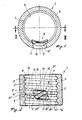
- a nut -generally shown at 1- comprises a tubular steel body 2 having a threading conventionally formed in its internal surface including a conti nuous rounded bottom thread 3 having edges 4 and 4' for the sli ding of a plurality of balls 5.
- the thread depth is less than the balls' diameter, whereby the latter are free to cooperate with a corresponding threading on a shaft (not shown) making up, together with the nut, the ball bearing screw assembly.
- said body 2 has a throu gh hole 7 for the exact housing of a improved deviating element according to the invention and generally shown at 8.
- the element 8 is formed by a body 9 having, when housed in said hole 7, a smooth external surface 10 arranged flush with the external surface of the body 2 and an internal surface having a sustantially S-shaped groove 11 with a bottom 11', as shown in Fig. 1, lower than the rounded bottom 3 of the inside threading of the nut.
- the groove 11 is defined by two opposite edges 12 and 12' arranged as continuation respectively of the edges 4 and 4' of said two adjoining thread portions 6 and 6', said edges 12 and 12' being obtained by providing the internal surface of the deviating element 8 with cylindrical bosses 13 and 13' of a cross-section corresponding to the section of the threading provided on the outer surface of the shaft, said bosses 13 and 13' being arranged in alignment with the thread portions 6 and 6' respecti vely so as to form mouths 11' and 11".
- the leading portions of the cylindri cal bosses 13 and 13' project beyond the body 9 to be accomoda ted within the inoperative branches 14 and 14' of the thread portions 6 and 6'.
- the body 9 also has side extensions 15 and 15' intended to bear on the ridges 16 and 16' joining alternate thread portions 6 and 6'..
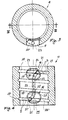
- the nut 17 is provided with two deviating elements, generally shown at 18 and 18', superimposed and respectively cooperating with a first thread 19 and a second thread 19'.
- Each deviating element 18 and 18' has an inner conduit 20 and 20', the conduit 20 having a mouth 21 exiting in the first thread 19 and a mouth 22 exiting into one end of an axial conduit 23 bored in the nut 17 and the conduit 20' having a mouth 21' exiting in the second thread 19' and a mouth 22' exiting into the other end of the axial conduit 23.
- the lead-in portions 24 and 24' of the mouth 21 and 21' are bored into cylindrical bosses 25 and 25' corresponding to the bosses 13 and 13' of the embodiment shown in Figs. 1 and 2.
- bosses 25 and 25' project beyond the elements 18 and 18' to be accomodated within the inoperative branches 26 and 26' of the thread portions 19 and 19', respectively. Also in this case side reteaning exten sions 27 are provided.
- bosses 13, 13' of Figs. 1 and 2 and the bosses 25, 25' of Figs. 3 and 4 make up a thickness for forning the edges 12, 12' and the lead-in portions 24, 24' so that the groove 11 of Figs. 1 and 2 and the conduits 20, 20' of Figs. 3 and 4 can be correctly joined to the relative thread portions, and thus avoiding any possible risk of impact of the balls 5 during recirculation.
- the cylindrical bosses will cooperate with the shaft's threading ensuring, together with the side extensions 15, 15' and 27,a correct and steady positioning of the deviating elements in the nut.
- a nut generally shown at 28 in Figs. 5 and 6.wherein the parts corresponding to those of Figs. 1 and 2 are indicated with the same reference numerals.
- the nut 28 is provided with a deviating element 29 providing for the recirculation of the balls 5 from one thread to the adjoining one and differs from the deviating element 8 in that it is provided, instead than the groove 11, with an inner conduit 30 bored in the same devia ting element 29.
Landscapes
- Engineering & Computer Science (AREA)
- General Engineering & Computer Science (AREA)
- Mechanical Engineering (AREA)
- Transmission Devices (AREA)
Applications Claiming Priority (2)
| Application Number | Priority Date | Filing Date | Title |
|---|---|---|---|
| IT22897/82A IT1153555B (it) | 1982-08-19 | 1982-08-19 | Dato con elemento di scambio perfezionato per viti a circolazione di sfere |
| IT2289782 | 1982-08-19 |
Publications (2)
| Publication Number | Publication Date |
|---|---|
| EP0103316A2 true EP0103316A2 (fr) | 1984-03-21 |
| EP0103316A3 EP0103316A3 (fr) | 1985-01-09 |
Family
ID=11201659
Family Applications (1)
| Application Number | Title | Priority Date | Filing Date |
|---|---|---|---|
| EP83201130A Withdrawn EP0103316A3 (fr) | 1982-08-19 | 1983-07-29 | Ecran pour vis à billes ayant un élément déviateur de billes |
Country Status (3)
| Country | Link |
|---|---|
| EP (1) | EP0103316A3 (fr) |
| ES (1) | ES274048Y (fr) |
| IT (1) | IT1153555B (fr) |
Cited By (12)
| Publication number | Priority date | Publication date | Assignee | Title |
|---|---|---|---|---|
| FR2579515A1 (fr) * | 1985-04-01 | 1986-10-03 | Novatome | Procede de fabrication d'un deviateur pour systeme vis-ecrou a billes a recyclage interne |
| EP0289441A1 (fr) * | 1987-04-29 | 1988-11-02 | Waybol S.A. | Mécanisme à vis-écrou à recirculation des billes par guides équipés de supports demi-spheriques ayant un mouvement oscillant pour l'autoalignement des entrées du guide |
| US5005436A (en) * | 1988-02-11 | 1991-04-09 | R.G.B. S.P.A. | Recirculating ball screw-nut screw coupling |
| EP0636816A1 (fr) * | 1993-07-30 | 1995-02-01 | Dana Corporation | Guide de transfert d'une vis à bille |
| US5622082A (en) * | 1995-08-22 | 1997-04-22 | Thomson Saginaw Ball Screw Company, Inc. | Ball nut and screw assemblies with improved crossovers |
| US5937700A (en) * | 1998-05-12 | 1999-08-17 | Thomson Saginaw Ball Screw Company, L.L.C. | Externally installable ball return crossover systems for ball nut and screw assemblies and methods of constructing and installing them |
| US6112610A (en) * | 1997-08-05 | 2000-09-05 | Thomson Saginaw Ball Screw Company, Llc | Externally insertable self-retaining crossover for ball nut and screw assemblies |
| WO2004027286A3 (fr) * | 2002-09-17 | 2004-10-14 | Ina Schaeffler Kg | Vis d'entrainement a billes et procede de fabrication d'un ecrou notamment destine a une vis d'entrainement a billes |
| EP1584542A1 (fr) * | 2004-04-07 | 2005-10-12 | Ntn Corporation | Assemblage vis-écrou à billes pour véhicules automobiles |
| KR100986127B1 (ko) * | 2005-06-20 | 2010-10-07 | 이관호 | 볼쐐기식 감속기 |
| CN105276114A (zh) * | 2014-06-16 | 2016-01-27 | 上银科技股份有限公司 | 隧道式滚珠螺杆 |
| FR3160441A1 (fr) * | 2024-03-22 | 2025-09-26 | Ntn Europe | Organe fileté à recirculation et mécanisme de vis à billes |
Family Cites Families (5)
| Publication number | Priority date | Publication date | Assignee | Title |
|---|---|---|---|---|
| GB879462A (en) * | 1957-02-13 | 1961-10-11 | Cam Gears Ltd | Improvements in screw and nut gear |
| US3161073A (en) * | 1961-10-02 | 1964-12-15 | Scully Jones & Co | Ball screw mechanism |
| FR2204271A5 (fr) * | 1972-10-20 | 1974-05-17 | Tech Integrale S | |
| FR2249578A5 (fr) * | 1973-10-30 | 1975-05-23 | Tech Integrale | |
| FR2306381A1 (fr) * | 1975-03-18 | 1976-10-29 | Luc Jacques | Ecrou a circulation de billes non recyclees |
-
1982
- 1982-08-19 IT IT22897/82A patent/IT1153555B/it active
-
1983
- 1983-07-29 EP EP83201130A patent/EP0103316A3/fr not_active Withdrawn
- 1983-08-18 ES ES274048U patent/ES274048Y/es not_active Expired
Cited By (14)
| Publication number | Priority date | Publication date | Assignee | Title |
|---|---|---|---|---|
| EP0198750A1 (fr) * | 1985-04-01 | 1986-10-22 | Novatome | Procédé de fabrication d'un déviateur pour système vis-écrou à billes à recyclage interne |
| FR2579515A1 (fr) * | 1985-04-01 | 1986-10-03 | Novatome | Procede de fabrication d'un deviateur pour systeme vis-ecrou a billes a recyclage interne |
| EP0289441A1 (fr) * | 1987-04-29 | 1988-11-02 | Waybol S.A. | Mécanisme à vis-écrou à recirculation des billes par guides équipés de supports demi-spheriques ayant un mouvement oscillant pour l'autoalignement des entrées du guide |
| US5005436A (en) * | 1988-02-11 | 1991-04-09 | R.G.B. S.P.A. | Recirculating ball screw-nut screw coupling |
| EP0636816A1 (fr) * | 1993-07-30 | 1995-02-01 | Dana Corporation | Guide de transfert d'une vis à bille |
| US5622082A (en) * | 1995-08-22 | 1997-04-22 | Thomson Saginaw Ball Screw Company, Inc. | Ball nut and screw assemblies with improved crossovers |
| US6112610A (en) * | 1997-08-05 | 2000-09-05 | Thomson Saginaw Ball Screw Company, Llc | Externally insertable self-retaining crossover for ball nut and screw assemblies |
| US5937700A (en) * | 1998-05-12 | 1999-08-17 | Thomson Saginaw Ball Screw Company, L.L.C. | Externally installable ball return crossover systems for ball nut and screw assemblies and methods of constructing and installing them |
| WO2004027286A3 (fr) * | 2002-09-17 | 2004-10-14 | Ina Schaeffler Kg | Vis d'entrainement a billes et procede de fabrication d'un ecrou notamment destine a une vis d'entrainement a billes |
| US7536929B2 (en) | 2002-09-17 | 2009-05-26 | Ina-Schaeffler, Kg | Ball screw and method for producing a spindle nut, in particular of a ball screw |
| EP1584542A1 (fr) * | 2004-04-07 | 2005-10-12 | Ntn Corporation | Assemblage vis-écrou à billes pour véhicules automobiles |
| KR100986127B1 (ko) * | 2005-06-20 | 2010-10-07 | 이관호 | 볼쐐기식 감속기 |
| CN105276114A (zh) * | 2014-06-16 | 2016-01-27 | 上银科技股份有限公司 | 隧道式滚珠螺杆 |
| FR3160441A1 (fr) * | 2024-03-22 | 2025-09-26 | Ntn Europe | Organe fileté à recirculation et mécanisme de vis à billes |
Also Published As
| Publication number | Publication date |
|---|---|
| ES274048Y (es) | 1987-07-16 |
| IT8222897A0 (it) | 1982-08-19 |
| IT8222897A1 (it) | 1984-02-19 |
| IT1153555B (it) | 1987-01-14 |
| EP0103316A3 (fr) | 1985-01-09 |
| ES274048U (es) | 1984-01-16 |
Similar Documents
| Publication | Publication Date | Title |
|---|---|---|
| EP0103316A2 (fr) | Ecran pour vis à billes ayant un élément déviateur de billes | |
| EP0845619B1 (fr) | Appareil avec vis a billes | |
| US5791192A (en) | Ball return and piece structure of internal circulation type ball screw system | |
| US7363835B2 (en) | Ball screw apparatus | |
| EP0930450B1 (fr) | Vis a billes | |
| JPH11270650A (ja) | ボールねじ装置 | |
| KR20020063801A (ko) | 직선운동 안내 유닛 | |
| US7465094B2 (en) | Linear guide apparatus | |
| KR900002426B1 (ko) | 판넬 펀치 | |
| EP0426461A1 (fr) | Dispositif pour transmettre un couple de rotation par billes | |
| EP0164498B1 (fr) | Dispositif pour l'entraînement en va-et-vient d'une tige | |
| TWI907545B (zh) | 直線運動導引單元 | |
| JP2970051B2 (ja) | ボールねじ一体型直動案内ユニット | |
| JPH028178B2 (fr) | ||
| EP1624228B1 (fr) | Mécanisme à recirculation de billes et vis à billes | |
| JPS5853730Y2 (ja) | 磁気記録再生装置のガイドポスト装置 | |
| JPH0524819Y2 (fr) | ||
| JPH0535228Y2 (fr) | ||
| KR850000729B1 (ko) | 축상자속 전기기계 | |
| KR890001642Y1 (ko) | 무한궤도용 상·하부 로울러의 부싱(Bushing) | |
| JPH0659655U (ja) | 変速機のリバースアイドラギヤ支持装置 | |
| JPS5954584U (ja) | 流体噴射式織機の緯糸測長装置 | |
| JP2791863B2 (ja) | インクリボンカセット | |
| KR200206055Y1 (ko) | 테이프 레코더용 폴 베이스 장착구조 | |
| JPS5883558A (ja) | コイル插入機 |
Legal Events
| Date | Code | Title | Description |
|---|---|---|---|
| PUAI | Public reference made under article 153(3) epc to a published international application that has entered the european phase |
Free format text: ORIGINAL CODE: 0009012 |
|
| AK | Designated contracting states |
Designated state(s): DE FR GB IT |
|
| PUAL | Search report despatched |
Free format text: ORIGINAL CODE: 0009013 |
|
| AK | Designated contracting states |
Designated state(s): DE FR GB IT |
|
| 17P | Request for examination filed |
Effective date: 19850328 |
|
| 17Q | First examination report despatched |
Effective date: 19860618 |
|
| STAA | Information on the status of an ep patent application or granted ep patent |
Free format text: STATUS: THE APPLICATION IS DEEMED TO BE WITHDRAWN |
|
| 18D | Application deemed to be withdrawn |
Effective date: 19861029 |
|
| RIN1 | Information on inventor provided before grant (corrected) |
Inventor name: SCARAVELLA, ALFREDO |