EP0103384B1 - Système d'entrée d'air pour un moteur - Google Patents
Système d'entrée d'air pour un moteur Download PDFInfo
- Publication number
- EP0103384B1 EP0103384B1 EP83304390A EP83304390A EP0103384B1 EP 0103384 B1 EP0103384 B1 EP 0103384B1 EP 83304390 A EP83304390 A EP 83304390A EP 83304390 A EP83304390 A EP 83304390A EP 0103384 B1 EP0103384 B1 EP 0103384B1
- Authority
- EP
- European Patent Office
- Prior art keywords
- airstream
- engine
- duct
- intake duct
- housing
- Prior art date
- Legal status (The legal status is an assumption and is not a legal conclusion. Google has not performed a legal analysis and makes no representation as to the accuracy of the status listed.)
- Expired
Links
- 239000002245 particle Substances 0.000 claims description 29
- 238000000926 separation method Methods 0.000 claims description 11
- 230000003247 decreasing effect Effects 0.000 claims description 3
- 230000015572 biosynthetic process Effects 0.000 description 3
- 239000000463 material Substances 0.000 description 2
- 239000003921 oil Substances 0.000 description 2
- 239000004576 sand Substances 0.000 description 2
- 230000035939 shock Effects 0.000 description 2
- 230000000903 blocking effect Effects 0.000 description 1
- 125000004122 cyclic group Chemical group 0.000 description 1
- 230000009977 dual effect Effects 0.000 description 1
- 239000000428 dust Substances 0.000 description 1
- 239000000945 filler Substances 0.000 description 1
- 230000037406 food intake Effects 0.000 description 1
- 238000010438 heat treatment Methods 0.000 description 1
- 229910001385 heavy metal Inorganic materials 0.000 description 1
- 230000002452 interceptive effect Effects 0.000 description 1
- 230000004048 modification Effects 0.000 description 1
- 238000012986 modification Methods 0.000 description 1
- 239000010705 motor oil Substances 0.000 description 1
- 230000002093 peripheral effect Effects 0.000 description 1
- XLYOFNOQVPJJNP-UHFFFAOYSA-N water Substances O XLYOFNOQVPJJNP-UHFFFAOYSA-N 0.000 description 1
Images




Classifications
-
- B—PERFORMING OPERATIONS; TRANSPORTING
- B64—AIRCRAFT; AVIATION; COSMONAUTICS
- B64D—EQUIPMENT FOR FITTING IN OR TO AIRCRAFT; FLIGHT SUITS; PARACHUTES; ARRANGEMENT OR MOUNTING OF POWER PLANTS OR PROPULSION TRANSMISSIONS IN AIRCRAFT
- B64D33/00—Arrangement in aircraft of power plant parts or auxiliaries not otherwise provided for
- B64D33/02—Arrangement in aircraft of power plant parts or auxiliaries not otherwise provided for of combustion air intakes
-
- F—MECHANICAL ENGINEERING; LIGHTING; HEATING; WEAPONS; BLASTING
- F02—COMBUSTION ENGINES; HOT-GAS OR COMBUSTION-PRODUCT ENGINE PLANTS
- F02C—GAS-TURBINE PLANTS; AIR INTAKES FOR JET-PROPULSION PLANTS; CONTROLLING FUEL SUPPLY IN AIR-BREATHING JET-PROPULSION PLANTS
- F02C7/00—Features, components parts, details or accessories, not provided for in, or of interest apart form groups F02C1/00 - F02C6/00; Air intakes for jet-propulsion plants
- F02C7/04—Air intakes for gas-turbine plants or jet-propulsion plants
- F02C7/05—Air intakes for gas-turbine plants or jet-propulsion plants having provisions for obviating the penetration of damaging objects or particles
-
- B—PERFORMING OPERATIONS; TRANSPORTING
- B64—AIRCRAFT; AVIATION; COSMONAUTICS
- B64D—EQUIPMENT FOR FITTING IN OR TO AIRCRAFT; FLIGHT SUITS; PARACHUTES; ARRANGEMENT OR MOUNTING OF POWER PLANTS OR PROPULSION TRANSMISSIONS IN AIRCRAFT
- B64D33/00—Arrangement in aircraft of power plant parts or auxiliaries not otherwise provided for
- B64D33/02—Arrangement in aircraft of power plant parts or auxiliaries not otherwise provided for of combustion air intakes
- B64D2033/022—Arrangement in aircraft of power plant parts or auxiliaries not otherwise provided for of combustion air intakes comprising bird or foreign object protections
-
- B—PERFORMING OPERATIONS; TRANSPORTING
- B64—AIRCRAFT; AVIATION; COSMONAUTICS
- B64D—EQUIPMENT FOR FITTING IN OR TO AIRCRAFT; FLIGHT SUITS; PARACHUTES; ARRANGEMENT OR MOUNTING OF POWER PLANTS OR PROPULSION TRANSMISSIONS IN AIRCRAFT
- B64D33/00—Arrangement in aircraft of power plant parts or auxiliaries not otherwise provided for
- B64D33/02—Arrangement in aircraft of power plant parts or auxiliaries not otherwise provided for of combustion air intakes
- B64D2033/0266—Arrangement in aircraft of power plant parts or auxiliaries not otherwise provided for of combustion air intakes specially adapted for particular type of power plants
- B64D2033/0293—Arrangement in aircraft of power plant parts or auxiliaries not otherwise provided for of combustion air intakes specially adapted for particular type of power plants for turboprop engines
-
- Y—GENERAL TAGGING OF NEW TECHNOLOGICAL DEVELOPMENTS; GENERAL TAGGING OF CROSS-SECTIONAL TECHNOLOGIES SPANNING OVER SEVERAL SECTIONS OF THE IPC; TECHNICAL SUBJECTS COVERED BY FORMER USPC CROSS-REFERENCE ART COLLECTIONS [XRACs] AND DIGESTS
- Y02—TECHNOLOGIES OR APPLICATIONS FOR MITIGATION OR ADAPTATION AGAINST CLIMATE CHANGE
- Y02T—CLIMATE CHANGE MITIGATION TECHNOLOGIES RELATED TO TRANSPORTATION
- Y02T50/00—Aeronautics or air transport
- Y02T50/60—Efficient propulsion technologies, e.g. for aircraft
Definitions
- This invention relates to an air intake system for separating foreign particles and other objects from air flowing into the inlet of a gaseous power plant such as a gas turbine engine.
- Aircraft engines in particular are susceptible to ingesting objects such as birds, hail, sand, stones, pieces of tire and the like. Such objects can damage or destroy such an engine, particularly if it is a small high speed engine.
- a gas turbine is intallled in an aircraft in a nacelle which has an air intake duct providing a first substantially rearward path leading from a forwardly facing air intake opening below the engine.
- Guide means in the duct separate a primary airstream to guide it along a second path at a substantial angle to the first, rearwardly extending path to supply air to the engine air inlet.
- a secondary stream of intake air is allowed to continue rearwards through an exit passage to the surrounding atmosphere. Debris carried in with the air through the air intake opening therefore tends to continue straight through and be discharged through the air exit passage.
- a hopper is formed in the exit passage where supercooled water and particles of ice are allowed to accumulate without restricting the outlet passage and a cyclic ice shedder is provided to dislodge the accumulated material so that it can be discharged through the exit passage.
- US 3329377 is a further example of a separator for a gas turbine engine in which a primary airstream entering along a rearwardly directed path is turned through a large angle to flow to the engine air inlet while a secondary stream is allowed to continue rearwards out of the nacelle.
- a separator for removing foreign particles and comprising an air intake duct extending rearwardly from an air intake opening for an intake airstream to flow in a first substantially rearward path therein, and means for separating from said intake airstream a primary airstream and for guiding said primary airstream along a second path at a substantial angle to the first path for passage into the engine air inlet, the intake duct being arranged to discharge a secondary stream of air from the intake airstream along a third path rearwardly so that particles entering the duct with the intake airstream will tend to travel with said secondary airstream to be separated from the primary airstream, a plenum being disposed behind the intake duct in the path of said secondary airstream and the particles carried by the secondary airstream being separated in said plenum from the airstream, duct means being connected to the plenum to guide a fourth stream of air from the plenum forwardly along a third path substantially separated from the third path and then to discharge said air smoothly into the primary airstream, forwardly of the rearmost part
- Figure 1 shows a typical engine, nacelle and air intake system of the kind presently used in certain aircraft made by The de Havilland Aircraft of Canada, Limited.
- a gas turbine engine 12 which drives a propeller 14 through a gearbox 16.
- the engine 12 is mounted with its air inlet 18 located at the rear of the engine and opening radially into a large plenum 20. Air enters an intake duct 22, travels rearwardly, and then travels upwardly through a screen 24 into the engine 12.
- Figure 2 shows a system used in many aircraft at the present time.
- the engine 12 faces forwardly and air for the engine enters an intake duct 28 and travels directly into the engine. There is no arrangement for removing foreign objects which are ingested, and any such foreign objects may damage the engine.
- FIG 3 shows a modification of the Figure 2 arrangement of a kind which has been currently proposed for removing foreign objects and particles.
- a bypass duct 30 branches off the main intake duct 32 and removes about 15% of the intake air as bypass air.
- a screen 34 in the main duct 32 just downstream of the bypass duct 30 prevents foreign objects from travelling into the engine.
- the screen 34 is formed from heavy metal rods.
- the Figure 3 arrangement has several serious disadvantages. Firstly, the screen 34, even though made of heavy material, must be shock mounted in order to withstand the impact of heavy objects such as birds. Secondly, because the screen 34 tends to ice, it must be electrically heated, thereby adding to the complexity and cost of the arrangement. Thirdly, each of the three ends of the intake duct arrangement must be shock mounted by means of a corrugated mounting, which adds weight and cost. Fourthly, when the engine is to be serviced, the nacelle must be removed and then the three branches of the intake duct must be separately removed, adding to the cost of servicing the engine. Finally, the loss of 15% of the intake air as bypass flow causes a reduction in the efficiency of the engine.
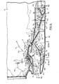
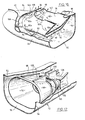
- FIG. 5 to 17 A preferred intake structure 40 according to the invention is shown in Figures 5 to 17 and has been found to operate in a highly satisfactory manner.
- the structure 40 will first be described generally with reference to Figures 5 and 9.
- the intake structure 40 includes a main intake duct 42.
- An inlet airstream 44 enters duct 42 and is divided into a primary airstream 46 and a secondary airstream 48.
- the primary airstream 46 turns sharply upwardly and then travels directly into the engine inlet 50 and through the engine intake duct indicated in dotted lines at 51.
- the secondary airstream 48 travels directly rearwardly into a plenum 52 located behind duct 42. Birds, stones, ice and the like entering the main intake duct 42 simply travel straight through the plenum 52 as shown by arrows 56, and exit through a door 58 which is opened when required.
- a third airstream 60 (which may be equal to the entire secondary airstream 48 if no other air is removed from the plenum 52) travels forwardly through an air duct 64 located below and to the sides of the main intake duct 42.
- the third airstream 60 When the third airstream 60 reaches the front end of the air duct 64, it divides into two streams 60a, 60b, one travelling upwardly on each side of the main air intake duct 42.
- the airstreams 60a, 60b rejoin as stream 60c at the top of the main air intake duct 42, and then travel rearwardly and upwardly through the peripheral gap formed by the engine inlet 50 and intake lip 86 (to be described), to rejoin the primary airstream 46 flowing into the engine inlet 50 and engine intake duct 51.
- a portion of the third airstream also travels from the plenum 52 directly forwardly and upwardly at the sides of the intake duct 42 to rejoin the primary air stream, as will be described.
- the invention solves a problem which in the past had been thought to be almost impossible to solve, i.e. it permits bypass of foreign objects without complexity and without creating significant instabilities, icing problems or substantial losses.
- the intake structure 40 is formed as a unit in a housing 72 connected at its rear to the nacelle 10 by hinges 73.
- the intake structure 40 is normally held in closed position against the nacelle 10 by a set of latches 74 ( Figure 6) which are conventional in nature and therefore will not be described in detail.
- the latches 74 can be released and the intake structure 40 swung downwardly as shown in Figure 8 for engine servicing.
- The. main intake duct 42 is centered laterally within the housing 72.
- the intake duct 42 is generally rectangular in cross-section, as shown in the drawings, but with rounded sides 76 and an inlet opening 77.
- the bottom wall 78 of the main intake duct 42 terminates in the cusp or V-shaped formation 68, which consists of an upwardly curved bottom wall portion 80 and a straight bottom wall portion 82. Both terminate at rear edges 80a, 82a located directly beneath the engine inlet 50, with a concave filler plate 83 extending therebetween.
- the V-shaped formation or cusp 68 extends upwardly to the upper wall 98 (to be described) of the housing, as shown in Figures 9, 12 and 16.
- the top wall 84 of the main intake duct 42 slopes slightly upwardly rearwardly along the bulk of its length and then at its rear curves sharply upwardly at a curved portion 86, terminating just above the bottom of the engine inlet 50.
- the rear edge 88 of the curved portion 86 also forms the front edge of a top opening 90 ( Figures 6, 9 and 16) from the main intake duct 42 into the engine inlet 50.
- the curved portion 86 extends above the opening 90 and into the inlet 50 to help guide the primary airstream 46 upwardly into the inlet 50.
- the housing 72 includes a bottom wall 92, sidewalls 94, a front wall 96, and an upper wall 98.
- a front opening 100 for the main intake duct 42 is located in the front wall 84 of the housing.
- the housing sidewalls 94 extend above the housing upper wall 98 along the front part of the housing 78 and terminate in a formed rim 102 (Figure 6).
- the rim 102 is shaped to fit the contour of the lower edge of the nacelle 10 and also to ensure that the entire housing 72 can be firmly secured to the nacelle.
- the shape of the rim 102 is also arranged to facilitate access to the front of the engine 12.
- the housing sidewalls 94 each include an upwardly projecting portion 104 adjacent the front thereof, as best shown in Figures 6 to 8 and 14.
- the upwardly projecting sidewall portions 104 help to ensure that the housing 72 will not detach from the nacelle 10 in use and also, when the housing 72 is swung downwardly, expose the sides of the from of engine 12 for servicing
- the lower portion 64a of the air duct 64 is defined in part by the space between the bottom wall 78 of the main intake duct 42 and the bottom wall 92 of the housing 72.
- the side portions 64b of the air duct 64 are formed by the spaces between the sidewalls 76 of the main intake duct 42 and the sidewalls 94 of the housing 72.
- the front of the air duct 64 is defined by a curved plate 106, best shown in Figures 9 and 15, which extends from the housing bottom wall 92 upwardly to a position above the front part of the main intake duct top wall 84.
- the curved plate 106 has a hole 107 therein for the intake duct 42 to pass therethrough.
- the top portion 64c of the air duct 64 is defined by the space between the upper part of the curved plate 106 and the curved rear portion 86 of the top wall 84 of the main intake duct 42.
- a longitudinally extending vertical divider plate 108 within the secondary air duct 54 divides the air duct 64 laterally into two equal parts to improve the stability of the third airstream 60 as it travels upwardly on each side of the main intake duct 42.
- its upper wall 98 extends from the front wall 96 over the curved plate 106, and is secured to the housing front wall 96, the curved plate 106, and the sidewalls 94. The upper wall 98 then extends rearwardly to the rear of the housing 72.
- the upper wall 98 includes a generally heart shaped opening 110 bordered by an upstanding rim 112.
- the opening 110 is shaped to match the shape of a standard engine inlet 50.
- the inlet 50 includes a downwardly and outwardly flared rim 114 ( Figure 9) fitted with a conventional outwardly facing O-ring 116 against which the rim 112 seals when the housing 72 is swung to its closed position.
- the plenum 52 in the rear portion of housing 72, is defined by two generally funnel-shaped structures 118, 120, best shown in Figures 9 and 17, which guide air (and particles) along a path of decreasing cross-sectional area toward the door 58.
- the funnel-shaped structures 118, 120 are separated by a space 122 which allows a fourth stream of air 124 (but not particles) travelling rearwardly through the funnel-shaped structures to travel upwardly and then rearwardly through the open rear end of the housing 72 and into an engine oil cooler 126 located behind the housing 72.
- This allows the intake structure 40 to perform dual duty, in that it provides particle free air both for the engine and also for the oil cooler of the engine.
- the funnel-shaped structures 118, 120 are supported by flanges 128, 130 which extend from the tops of the structures 118, 120 to the upper wall 98 of the housing 72.
- the door 58 includes a sector-shaped front surface 132, a flat lower surface 134 which is flush with the housing bottom wall 92 when the door is closed, and an upper surface 136 connected to a hydraulic actuator 138.
- the actuator 138 moves it to the dotted line position in Figure 9, permitting particles and other objects to exit from the intake structure.
- the third airstream 60 travels forwardly through the air duct 64 (including portions 64a, 64b thereof) beneath and to the sides of the main intake duct 42.
- the third airstream 60 is equal in flow to the secondary airstream 48 less the sum of any air flows travelling to the trapdoor 58, or to the oil cooler 126, or lost in leaks.
- the main portion of the third airstream 60 flows from lower duct 64 upwardly on each side of the main intake duct 42, and then rearwardly and upwardly through duct portion 64c, over curved portion 86 and into the engine inlet 50.
- a part 60d of the third airstream 60 may also tend to travel around the sides of the cusp 68, directly forwardly and upwardly over the sides of the main intake duct 42, and then over the side edges of the upper opening 90 in the main intake duct 42.
- the upper side edges of opening 90 are cut back or notched as indicated at 142, from a location forwardly of the stagnation point S forwardly to blend in with the lip 88 forming a continuous flow gap between duct 42 and engine inlet 50.
- Rearwardly of notches 142 the upper side edges of duct 42 seal against the top surface 98 of the structure, as shown in Figure 9. This prevents secondary air from feeding forwardly into the engine inlet 50 aft of the stagnation point S and causing flow separation.
- lip 88 which defines the dimension of the flow gap between the duct 42 and the engine inlet 50, is important. This lip, which guides the primary airstream 46, should be located so as to provide efficient turning of the primary airstream 46 into the engine inlet. 50. Thus the lip 88 should not be too far from wall 51a. However, the spacing must be sufficient so as not to choke off the third airstream 60c. However, the spacing between lip 88 and wall 51 a should be sufficiently small as not to create a larger third airstream than necessary, since it is desired to have most of the intake air travel directly into the engine inlet 50 which is the most efficient path.
- the plenum 52 is pressurized, helping to produce a positive pressure on the convex side of the primary airstream 46 flowing through the main intake duct 42 into the engine inlet 50. This helps to deflect the primary airstream 46 into the engine inlet, although of course the main deflecting force consists of the suction produced by the engine. As mentioned, the main separation of the primary and secondary airstreams occurs at the stagnation point S which will vary in position with variation of the third airstream to primary airstream flow ratio.
- the cusp 68 which produces an air roller bearing 70, separates the secondary and third airstreams from each other, and thus reduces losses in the system. Without such flow separation, buffeting between the forward and rearward flows tends to occur, and this creates not only losses but also undesired vibrations.
- a further advantage of the system shown is that a simple boot de-icing system may be used, consisting simply of an expansible rubber boot (not shown) fitted around the opening 100 of the main air intake duct 42. Although ice will be
- a complex anti-icing system (consisting of heating structure to prevent the formation of ice on engine intake screens) is not normally required.
- the separator of the invention can be differently oriented with respect to the engine, and can be used with engines in applications other than in aircraft but where dust or particles may present a problem.
Landscapes
- Engineering & Computer Science (AREA)
- Chemical & Material Sciences (AREA)
- Combustion & Propulsion (AREA)
- Aviation & Aerospace Engineering (AREA)
- Mechanical Engineering (AREA)
- General Engineering & Computer Science (AREA)
- Cooling, Air Intake And Gas Exhaust, And Fuel Tank Arrangements In Propulsion Units (AREA)
Claims (16)
Applications Claiming Priority (2)
| Application Number | Priority Date | Filing Date | Title |
|---|---|---|---|
| CA409600 | 1982-08-17 | ||
| CA000409600A CA1201894A (fr) | 1982-08-17 | 1982-08-17 | Prise d'air pour moteur a explosion |
Publications (3)
| Publication Number | Publication Date |
|---|---|
| EP0103384A2 EP0103384A2 (fr) | 1984-03-21 |
| EP0103384A3 EP0103384A3 (en) | 1984-07-11 |
| EP0103384B1 true EP0103384B1 (fr) | 1988-09-28 |
Family
ID=4123425
Family Applications (1)
| Application Number | Title | Priority Date | Filing Date |
|---|---|---|---|
| EP83304390A Expired EP0103384B1 (fr) | 1982-08-17 | 1983-07-29 | Système d'entrée d'air pour un moteur |
Country Status (3)
| Country | Link |
|---|---|
| EP (1) | EP0103384B1 (fr) |
| CA (1) | CA1201894A (fr) |
| DE (1) | DE3378137D1 (fr) |
Cited By (1)
| Publication number | Priority date | Publication date | Assignee | Title |
|---|---|---|---|---|
| US9500129B2 (en) | 2012-10-29 | 2016-11-22 | Honeywell International Inc. | Turboshaft engines having improved inlet particle scavenge systems and methods for the manufacture thereof |
Families Citing this family (15)
| Publication number | Priority date | Publication date | Assignee | Title |
|---|---|---|---|---|
| US4685942A (en) * | 1982-12-27 | 1987-08-11 | General Electric Company | Axial flow inlet particle separator |
| GB2203801B (en) * | 1987-04-14 | 1991-11-27 | Rolls Royce Plc | A gas turbine engine |
| US4938021A (en) * | 1988-10-27 | 1990-07-03 | Sundstrand Corporation | Sustainer propulsion system |
| US5123240A (en) * | 1990-03-19 | 1992-06-23 | General Electric Co. | Method and apparatus for ejecting foreign matter from the primary flow path of a gas turbine engine |
| GB2259328B (en) * | 1991-09-03 | 1995-07-19 | Gen Electric | Gas turbine engine variable bleed pivotal flow splitter |
| GB9906621D0 (en) * | 1999-03-23 | 1999-05-19 | British Aerospace | Vehicle propulsion systems |
| RU2174616C2 (ru) * | 1999-09-21 | 2001-10-10 | Государственное унитарное предприятие "Завод им. В.Я. Климова" - дочернее предприятие государственного унитарного предприятия Военно-промышленный комплекс "МАПО" | Входное устройство для турбовинтового двигателя |
| RU2189474C1 (ru) * | 2000-12-27 | 2002-09-20 | Общество с ограниченной ответственностью "Проектно-конструкторское бюро "Энергия" | Способ подачи и отвода потока очищенного охлаждающего воздуха к турбогенератору |
| KR20090008479A (ko) * | 2004-09-15 | 2009-01-21 | 가부시키가이샤 엔.티.티.도코모 | 이동 통신 시스템, 무선 제어국, 무선 기지국, 이동국 및 이동 통신 방법 |
| EP1674694B1 (fr) * | 2004-12-23 | 2014-02-12 | Rolls-Royce plc | Conduite d'aspiration pour compresseur |
| EP2192787B1 (fr) * | 2008-11-28 | 2011-01-26 | Alcatel Lucent | Procédé et appareil de protection d'équipement |
| US20120070271A1 (en) | 2010-09-21 | 2012-03-22 | Urban Justin R | Gas turbine engine with bleed duct for minimum reduction of bleed flow and minimum rejection of hail during hail ingestion events |
| FR3039209B1 (fr) * | 2015-07-23 | 2017-07-14 | Snecma | Manche d’entree d’air pour un turbopropulseur d’aeronef |
| FR3075761A1 (fr) * | 2017-12-21 | 2019-06-28 | Airbus Operations | Partie anterieure de nacelle d'un ensemble propulsif comportant un cadre de rigidification incline |
| CN121448623B (zh) * | 2026-01-07 | 2026-03-03 | 天津天陆嘉航科技有限公司 | 一种防砂面板与进气流道可拆分的进气防护装置 |
Family Cites Families (3)
| Publication number | Priority date | Publication date | Assignee | Title |
|---|---|---|---|---|
| US3329377A (en) * | 1965-10-11 | 1967-07-04 | United Aircraft Canada | Protection for aircraft engines against snow, ice and airborne particles |
| US3371471A (en) * | 1965-10-15 | 1968-03-05 | Avco Corp | Sand and dust collector for engine air inlets |
| US3952972A (en) * | 1974-12-24 | 1976-04-27 | United Aircraft Of Canada Limited | Inertial separator |
-
1982
- 1982-08-17 CA CA000409600A patent/CA1201894A/fr not_active Expired
-
1983
- 1983-07-29 EP EP83304390A patent/EP0103384B1/fr not_active Expired
- 1983-07-29 DE DE8383304390T patent/DE3378137D1/de not_active Expired
Non-Patent Citations (1)
| Title |
|---|
| PRODUCT ENGINEERING, vol. 45, no. 6, June 1974, Cleveland, GB, "Turboprop aircraft is reliable, easy to maintain", pp. 12,13 * |
Cited By (1)
| Publication number | Priority date | Publication date | Assignee | Title |
|---|---|---|---|---|
| US9500129B2 (en) | 2012-10-29 | 2016-11-22 | Honeywell International Inc. | Turboshaft engines having improved inlet particle scavenge systems and methods for the manufacture thereof |
Also Published As
| Publication number | Publication date |
|---|---|
| CA1201894A (fr) | 1986-03-18 |
| DE3378137D1 (en) | 1988-11-03 |
| EP0103384A2 (fr) | 1984-03-21 |
| EP0103384A3 (en) | 1984-07-11 |
Similar Documents
| Publication | Publication Date | Title |
|---|---|---|
| US4456458A (en) | Air intake system for engine | |
| EP0103384B1 (fr) | Système d'entrée d'air pour un moteur | |
| US4346860A (en) | Vane fairing for inertial separator | |
| CA1229494A (fr) | Prise d'air a separateur pour moteur aeronautique | |
| CA2614432C (fr) | Separateur de particules utilisant une regulation de la couche limite | |
| US7611093B2 (en) | Dual flow APU inlet and associated systems and methods | |
| US5123240A (en) | Method and apparatus for ejecting foreign matter from the primary flow path of a gas turbine engine | |
| US4836473A (en) | Apparatus for influencing a boundary layer on the surface of a body moving through a medium | |
| EP2969764B1 (fr) | Systèmes de protection d'entrée interchangeables pour admissions d'air de moteurs d'avion et procédés associés | |
| US4004760A (en) | Device for preventing foreign matters from being sucked into a gas turbine engine for an aircraft | |
| US5042603A (en) | Engine air intake apparatus | |
| US20090261208A1 (en) | Aircraft engine inlet pivotable barrier filter | |
| DE2452526A1 (de) | Verbesserungen an den dynamischen lufteintritten der turboantriebe von drehfluegel-flugzeugen | |
| GB2205903A (en) | Variable geometry jet engine nacelle | |
| US4502875A (en) | Air intakes of aircraft mounted gas turbine engines | |
| US6116015A (en) | Breather outlet | |
| US4425756A (en) | Gas turbine engine and its associated air intake system | |
| US3513641A (en) | Foreign particle separator for an air moving member | |
| US8801823B2 (en) | Device, method, and system to separate liquid and particulate matter from the airstream of a centrifugal fan | |
| JPH04272432A (ja) | ブリーザ出口 | |
| US8539748B2 (en) | Segmented inertial particle separators and methods of assembling turbine engines | |
| US10266275B1 (en) | Pressure recovery device for an aircraft engine air intake | |
| US2405102A (en) | Air intake filter for aircraft engines | |
| JPS63117127A (ja) | 異物の分離装置 | |
| US20110088652A1 (en) | Ram induction system |
Legal Events
| Date | Code | Title | Description |
|---|---|---|---|
| PUAI | Public reference made under article 153(3) epc to a published international application that has entered the european phase |
Free format text: ORIGINAL CODE: 0009012 |
|
| AK | Designated contracting states |
Designated state(s): DE FR GB IT |
|
| PUAL | Search report despatched |
Free format text: ORIGINAL CODE: 0009013 |
|
| AK | Designated contracting states |
Designated state(s): DE FR GB IT |
|
| 17P | Request for examination filed |
Effective date: 19841222 |
|
| GRAA | (expected) grant |
Free format text: ORIGINAL CODE: 0009210 |
|
| AK | Designated contracting states |
Kind code of ref document: B1 Designated state(s): DE FR GB IT |
|
| REF | Corresponds to: |
Ref document number: 3378137 Country of ref document: DE Date of ref document: 19881103 |
|
| ITF | It: translation for a ep patent filed | ||
| ET | Fr: translation filed | ||
| PLBE | No opposition filed within time limit |
Free format text: ORIGINAL CODE: 0009261 |
|
| STAA | Information on the status of an ep patent application or granted ep patent |
Free format text: STATUS: NO OPPOSITION FILED WITHIN TIME LIMIT |
|
| 26N | No opposition filed | ||
| ITTA | It: last paid annual fee | ||
| ITPR | It: changes in ownership of a european patent |
Owner name: CAMBIO RAGIONE SOCIALE;DE HAVILLAND CANADA LTD |
|
| REG | Reference to a national code |
Ref country code: FR Ref legal event code: CD |
|
| REG | Reference to a national code |
Ref country code: FR Ref legal event code: TP |
|
| ITPR | It: changes in ownership of a european patent |
Owner name: CESSIONE;BOEING OF CANADA LTD "DOWNSVIEW" |
|
| ITPR | It: changes in ownership of a european patent |
Owner name: CESSIONE;DE HAVILLAND INC. |
|
| REG | Reference to a national code |
Ref country code: FR Ref legal event code: TP |
|
| REG | Reference to a national code |
Ref country code: FR Ref legal event code: TP |
|
| REG | Reference to a national code |
Ref country code: GB Ref legal event code: 732E |
|
| REG | Reference to a national code |
Ref country code: GB Ref legal event code: IF02 |
|
| PGFP | Annual fee paid to national office [announced via postgrant information from national office to epo] |
Ref country code: GB Payment date: 20020725 Year of fee payment: 20 |
|
| PGFP | Annual fee paid to national office [announced via postgrant information from national office to epo] |
Ref country code: FR Payment date: 20020821 Year of fee payment: 20 |
|
| PGFP | Annual fee paid to national office [announced via postgrant information from national office to epo] |
Ref country code: DE Payment date: 20020824 Year of fee payment: 20 |
|
| PG25 | Lapsed in a contracting state [announced via postgrant information from national office to epo] |
Ref country code: GB Free format text: LAPSE BECAUSE OF EXPIRATION OF PROTECTION Effective date: 20030728 |
|
| REG | Reference to a national code |
Ref country code: GB Ref legal event code: PE20 |