EP0103393B1 - Détecteur de véhicule à boucle inductive - Google Patents
Détecteur de véhicule à boucle inductive Download PDFInfo
- Publication number
- EP0103393B1 EP0103393B1 EP83304551A EP83304551A EP0103393B1 EP 0103393 B1 EP0103393 B1 EP 0103393B1 EP 83304551 A EP83304551 A EP 83304551A EP 83304551 A EP83304551 A EP 83304551A EP 0103393 B1 EP0103393 B1 EP 0103393B1
- Authority
- EP
- European Patent Office
- Prior art keywords
- oscillator
- loop
- timer
- counter
- cycles
- Prior art date
- Legal status (The legal status is an assumption and is not a legal conclusion. Google has not performed a legal analysis and makes no representation as to the accuracy of the status listed.)
- Expired
Links
Images


Classifications
-
- G—PHYSICS
- G08—SIGNALLING
- G08G—TRAFFIC CONTROL SYSTEMS
- G08G1/00—Traffic control systems for road vehicles
- G08G1/01—Detecting movement of traffic to be counted or controlled
- G08G1/042—Detecting movement of traffic to be counted or controlled using inductive or magnetic detectors
Definitions
- This invention relates to a vehicle detector, and more particularly to an inductive loop type of vehicle detector in which the loop is made the frequency determining element of an oscillator.
- Period measurement is commonly made by measuring the period of a fixed number of loop oscillator cycles and making a decision on vehicle detection by comparing the measured period with a reference period itself generated in dependence upon a previous measurement. This basic procedure is to do no more than would be done by applying a frequency counter with a period measurement facility to the loop oscillator.
- That period is of course, a function of frequency and thus of loop inductance. The latter may vary widely with the size and shape of loop used in a particular installation.
- Vehicle detection is, in simple terms, made by determining whether the difference between the current clock pulse count and a preceding count exceeds a threshold value. It will be appreciated that the threshold expressed in a defined number of clock pulse counts represents a predetermined time deviation. Thus vehicle presence is defined on the basis of a predetermined time deviation as a percentage of an indeterminate time period which can have a wide range.
- This variance of percentage sensitivity can be controlled to some extent by allowing manual adjustment in the apparatus of the number of loop cycles counted or the threshold deviation but this requires a skilled setting up of each individual installation including some estimation of the likely oscillator frequency with the loop to be used.
- the number of loop counter settings is limited and once set to a count value that value remains whatever changes are made in the loop unless another special setting up procedure is performed.
- a vehicle detection apparatus connectable to a vehicle sensing loop and including an oscillator for oscillating at a frequency dependent on the inductance of the loop, means for repetitively measuring when the apparatus is in the detection mode the duration of a plural number of oscillator cycles, and means for analysing successive measured durations to determine the presence of a vehicle, characterised by a circuit arrangement for establishing in an initialising procedure the plural number of oscillator cycles whose duration is to be measured during the detection mode said circuit arrangement comprising:
- the circuit arrangement preferably includes means responsive to one or more specific conditions to initiate the number estabJishing procedure.
- One such condition is turning on power.
- Another is a general reset command.
- the timer is actuated.
- the apparatus operates in a normal detection mode using that number to set the number of oscillator cycles whose duration is measured until such time as circumstances arise requiring a fresh initialising procedure.
- the predetermined duration may be referred to hereinafter as the base time (or time base) and the established number of cycles as the operational cycle number.
- the circuit arrangement includes a microcomputer for controlling actuation of the timer, the number storing means being data storage associated with the microcomputer.
- the microcomputer also provides the means for analysing successive measured durations.
- the duration measuring means may include a pre-settable down counter which is set to a count value established by the stored number and is operable to count down to the set point, e.g. the count zero point.
- a further clock pulse source and a further counter operable in synchronism with the down counter are arranged for counting clock pulses up to the reaching of the set point so as to achieve a count value that is dependent on the duration of the aforesaid pre-set number in the down counter.
- operble in synchronism is meant that it is possible but not necessary for the further counter to start counting at exactly the same time as the down counter. They should however start in a defined relationship approximating a simultaneous start.
- the oscillator means can comprise a single oscillator circuit to which the loops are successively connected; a respective oscillator circuit for each loop in which case the oscillators may be selectively enabled as the scanning cycle progresses or the oscillators may be running continuously; or more than one oscillator circuit may be selectively connectable to a given loop.
- This latter instance is of importance where a loop at a particular location may be used for two traffic monitoring functions.
- the scanning of the loop with the two oscillators can be associated with differing sensitivites or other detection parameters in the analysing means, e.g. the microcomputer referred to above.
- a vehicle detection apparatus connectable to a vehicle sensing loop and including an oscillator for oscillating at a frequency dependent on the inductance of the loop, means for repetitively measuring the duration of a plural number of oscillator cycles, and analysing means analysing successive measured durations to determine the presence of a vehicle, characterised by a circuit arrangement comprising:
- the timer period does not need to be known though it needs to be accurately reproduced on each occasion the timer is actuated.
- the timer may provide an accurately defined pulse and be triggered in response to a positive-going (say) zero-crossing of the oscillator waveform (assuming this is sinusoidal) or by a defined edge of a pulse generated by the oscillator or from its waveform.
- a positive-going (say) zero-crossing of the oscillator waveform assuming this is sinusoidal
- a defined edge of a pulse generated by the oscillator or from its waveform For convenience, assume the second predetermined point on the oscillator waveform used in the time measurement is the next positive-going zero-crossing following the end of the timer pulse. It could be any nth such defined point where n is specified but the next following (n+1) point is preferred.
- a measurement of the time of the next positive-going zero-crossing following the trailing edge of the timer pulse is a measure of the duration from the trigger time since the pulse duration is the same in each case. In any event it is the variation in time which is of importance in making detection decisions and thus the measurement of the time between the trailing edge of the pulse and the next positive-going zero-crossing is entirely satisfactory.
- the base time i.e. the timer period
- the timer period is equal to a substantial number of times the oscillator period.
- Atypical timer period is contemplated to be 10mS equal to 500 oscillator cycles at say 50 kHz.
- the maximum period to the end of the time measurement would be 10mS plus 1 cycle which is 10.02 mS.
- the detection of a zero-crossing coincident with the end of this period, whether advancing or retreating in time, can be used to adjust the initial cycle count value.
- a calculation of the current oscillator period can then be made from the monitored number of cycles in the timer period. Thus the jump or transition from one cycle to the next can be allowed for in analysing the difference measurements and their direction and rate of change.
- Yet another approach which is presently preferred is to count, at each measurement, the number of cycles from the start of the timer period to the end of the next positive-going zero-crossing (to use the same example as above) following the timer period.
- This will be a precisely determinable interval containing a precisely determinable number of loop oscillator cycles.
- To calculate the loop oscillator period requires the timer period to be known, and it can be set with precision using digital counting techniques.
- the time difference, which will be called T between the end of the timer period and the next positive-going zero-crossing is also accurately measurable with digital counting techniques: and the total period will, in the example being considered, coincide with an intergral number of loop oscillator cycles that can be readily counted.
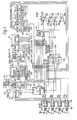
- FIG. 1 there is shown apparatus for scanning four loops (not shown) connectable to terminals 10ato 10d respectively.
- the loops are connected via respective isolating transformers 12a to 12d into the tank circuits of respective loop oscillators 14a to 14d that are of conventional form, e.g. Colpitts oscillators.
- the loop oscillators are sequentially scanned by successively applying to them an enable signal on respective terminals 16a to 16d.
- the enable signals are supplied from a microprocessor or microcomputer 100 to be described further below.
- Each loop oscillator has a respective output 18a to 18d that is applied through a limiter 20 to common signal-handling circuitry about which more is said below.
- the microcomputer 100 has four input devices 22a to 22d associated with it that store data relating to the detection parameters to be applied with a respectve loop. These devices need not be described in detail here but may comprise manually-settable switches and controllable buffer logic for reading the switch data to the microcomputer. Each device 22a-d has a respective enable input 24a to 24d connected to the respective enable input 16a to 16d of the associated loop. Thus a loop oscillator and its associated input device are selected simultaneously.
- the microcomputer also controls four output devices 26a to 26d associated with respective loops. Each device has a respective presence input 28a to 28d controlled by the microprocessor and is shown as having an output transistor 30a to 30d respectively, for example for actuating external relays or any other desired function.
- the precise nature of the output devices is not relevant to an understanding of this invention. They are not successively enabled during loop scanning but are actuated only when a vehicle presence is detected at the associated loop.
- the microcomputer is programmed to perform three main functions:- firstly, general control of the apparatus; secondly, data storage of both data acquired from operation of the loops and of input data from the devices 22; and thirdly, analysis of the loop data in accord with the detection parameters and the activation of an output device 26 when a vehicle presence is detected.
- the particular circuit illustrated is designed around the M6805 type device available from Motorola Inc. Numerous other devices are available. Choice largely resides in a balance of performance against cost.
- the microcomputer 100 has three ports 100A, B and C.
- Port 100A is an 8-bit bidirectional port used for data transfer.
- the port 100A is connected directly to the 8-bit programmable input of a pre-settable down counter 110 into which, for each loop oscillator measurement, is set a number determining the number of cycles of the oscillator whose duration is to be measured.
- the port 100A is also connected through data selection logic 112 to selectively receive 6-bit data from an enabled input device 22 supplied to a port 112A; to a 12-bit ripple counter 114 used in an initialisation procedure to be described connected to port 112B; and to a 16-bit ripple counter 116 used for the duration measurement connected to ports 112C and 112D.
- Both counters have each bit available as an output 0 0 to ON representing bit values 2° to 2N.
- the counter 114 e.g. a 4040 device
- the counter 114 has 11 bits used in the initialisation procedure (count up to 2048) but the three least significant bits are ignored as regards supplying data to the microcomputer and the twelfth bit ( Q ll) is used as a control output.
- an 8-bit input (bits 3 to 10) is connected to port 1128 of the logic 112.
- the 16- bit duration counter is used in full and in conventional manner its data is transferred in two 8-bit bytes to the 8-bit port 100A, the low and high bytes being connected to ports 112C and 112D respectively.
- the selector logic 112 uses readily available, three-state logic devices capable of buffering and switching up to 8-bits. Unless selected for data transfer the output of such devices is "neutral" and does not affect the high/ low states from a selected logic device connected to the microcomputer port 100A.
- Four control inputs 112E are used to control selection of the four ports 112A-D.
- the microcomputer has a second 8-bit port 100B four bits of which are dedicated to controlling respective output devices 26. Three of the other four bits are connected as inputs of a 3-to-8 line decoder 118, and the remaining bit on line 103 provides a master reset (MR) and a strobe input for pre-setting counter 110. The four output terminals of the decoder are connected to respective ones of the control inputs 112E.
- the microcomputer has a third, 4-bit port 100C whose terminals are connected to the respective enable inputs of loop oscillators 14a-d and their associated input devices 22a-d.
- the scanning sequence is derived at this port. By use of decoders up to fifteen loops could be scanned.
- the microcomputer has its clock input (clock) connected to a 4.433 MHz crystal-controlled clock pulse source 122 that also supplies clock pulses to the clock input (CK) of duration counter 116 through a gate 124.
- the transmission of clock pulses through the gate 124 is controlled by a second gate input that in turn is controlled by a logic unit 126.
- the signal inputs controlling the logic unit which operates as a latch are described further below.
- the selected loop oscillator supplies its frequency output, squared by limiter 20, to the clock input (CK) of counter 114, via a control gate 128 performing an AND function.
- the clock input (CK) of counter 110 is connected to the O2 output of counter 114 so that the latter acts as a divide-by-8 prescaler for counter 110. This is consistent with the ignoring of the three least significant bits in the data obtained from the counter 114 during the initialisation procedure. This data is used for pre-setting counter 110 as will be further described.
- the counter 110 has an output on line 130 that is actuated when the counter reaches zero and is supplied through an OR-gate 131 to input 126a of the logic unit 126 as a stop signal to denote the end of a loop measurement and terminate the supply of clock pulses to duration counter 116.
- the start of clock pulse counting by counter 116 for an individual loop measurement in normal operation is also controlled with the air of the counter 114.
- the start input 126b of the latching logic unit is connected to the Q 3 output of the counter 114.
- the reason for the start connection to output Q 3 arises out of adoption of sequential switching-on of the loop oscillators.
- the enabled oscillator is given a period to settle before duration measurement begins.
- the counter 114 provides this settling period by not enabling the gate 124 through logic unit 126 until the start of the 8th loop oscillator cycle.
- the counter 114 serves to synchronize the starting conditions for each loop measurement.
- the Q outputs are reset to low initially.
- Counters 110 and 114 are clocked on positive-and negative- going edges respectively at their clock input (CK).
- Counter 110 is first clocked at the beginning of the 8th loop oscillator cycle at which time the Q 3 output of the counter 114 goes high to provide the start signal to logic unit 126.
- the counter 114 is used in the initialisation procedure.
- the gate 128 through which it is clocked by the active loop oscillator is controlled by a timer 132 that is enabled by the microcomputer over line 102 to generate a pulse of 10 mS duration.
- the timer pulse is supplied to gate control input 128a to open the gate for loop cycle pulse transmission provided that a second control input 128b connected to the Q " output of counter 114 is low: which it normally will be.
- the decoder 118 is arranged to maintain the data selector logic 112 in a neutral state at that time.
- the output of the timer 132 is applied to the gate 128 through a further gate 129.
- This gate is enabled to pass timer pulses by logic 133 connected to two of the inputs of decoder 118.
- the purpose of this circuit is to enable the timer to supply its pulses during initialisation but to maintain input 128a enabled during loop measurement so as to be unaffected by the timer. Since only five of the input states of decoder 118 have been used for other control functions, there are states available which can be used by the microcomputer to control the timer output circuit.
- the output of the timer is also supplied through OR-gate 131 to the logic unit 126 as a means of signalling the end of a timer pulse to the microcomputer.
- the initialisation procedure is itself initiated by activation of a reset input 104 of microcomputer 100 by a reset condition sensing circuit 134.
- Circuit 134 is operable to generate a reset signal on initial application of power to the whole detector circuit (power-up) or by a manual or electrical reset input applied to it.
- the reset input causes the microcomputer to go into an initialisation routine and to issue a reset signal on line 103 that is supplied to the reset inputs (MR) of the counters 114 and 116, the timer 132 and the logic unit 126.
- the purpose of the initialisation procedure is to establish approximately the number of cycles of each loop oscillator that occur in the timer period and to store these numbers for use in the normal measurement operations. These numbers (or sub-multiples of them) constitute the operational cycle number for each loop.
- the microcomputer 100 enables the first loop oscillator 14a and, after a short delay determined within the microcomputer or by a separate timer, enables the timer 132 to generate its 10 mS pulse for the duration which gate 126 is open. Gate 129 is held open at this time. The delay allows the selected oscillator to settle and thereafter the counter 114 counts loop oscillator cycles for the 10 mS period. The circuit parameters are chosen so that even at the highest loop oscillator frequency the Q t1 output of counter 114 does not go high so that counting ceases at the end of the timer pulse. The end of the timer pulse is signalled to the INT terminal of the microcomputer by way of logic unit 126.
- the microcomputer may act on an internal timing operation chosen sufficiently long to ensure the timer pulse has ended.
- the microcomputer then activates the data selector logic 112 to transfer the bits at the Q 3 to Q 10 outputs of the counter 114 to port 100A. These bits are entered into memory space labelled as pertaining to the first loop oscillator.
- the resolution obtained by discarding the three least significant bits is to 8 loop oscillator cycles but this is consistent with the subsequent counting operation of the counter 110. Having acquired the data for the first loop oscillator, the procedure is repeated.
- the microcomputer issues a sequence of enable and master reset signals in order to successively enable oscillators 14b, c and d, enabling the timer each time, and so as to acquire from such loop oscillator a count value representing the number of cycles of each oscillator occurring in 10 mS.
- the four labelled, values are then available in the memory space for subsequent use
- the 10 mS period need not be precisely held; typically an accuracy of ⁇ 5% will suffice. It is sufficient to acquire an operational cycle number representing about 10 mS for each oscillator.
- This number is thus established at some value consequent on the operational condition of the relevant loop oscillator at the time the sample is taken. It is not set into the apparatus and may have different values at different times. The value achieved will not be known in normal use. It is the maintenance of the essentially constant time base that is important.
- the timer 132 is no longer required for normal operation.
- the gate 129 is held closed so that the enabling of the timer each time a strobe signal is applied to down counter 110 is of no practical effect.
- the microcomputer is now ready to perform a repetitive sampling and analysis routine on the four loop oscillators. As each oscillator is enabled for sampling the same procedure is gone through as follows, taking the first oscillator 14a as an example.
- the oscillator 14a is enabled and at the same time a reset signal is applied over line 103 to the counters 114 and 116. This same signal is applied as a strobe signal to the down counter 110.
- the microcomputer has made available from the memory space the operational cycle number pertaining to the first oscillator. This value appears at port 100A and the strobe signal presets this value into counter 110.
- the reset to the counter 114 not only clears the counter for the next counting operation but ensures that the control input 128b of gate 128 is low to allow transmission of loop oscillator pulses.
- the counter 114 immediately starts counting loop oscillator cycles and at every eight cycle applies a clock pulse to the counter 110 to reduce its count value by one.
- the Q 3 output of counter 114 activates the start input 126b of logic unit 126 to open gate 124.
- the counter 116 now starts counting clock pulses and this continues until the down counter 110 reaches zero whereupon the counter outputs a stop signal to logic unit 126 which closes the gate 124 to terminate clock pulse counting.
- the logic unit also signals the closure of gate 124 to an input INT of the microcomputer to inform the latter that the duration measuring operation is completed.
- the microcomputer now activates the selector logic 112 to read in the low and high bytes at ports 112Cand D and thereby acquire the count value in counter 116 as a measure of the duration of the number of loop cycles pre-set into the down counter 110.
- the enable signal at input 16a of oscillator 14a will have been held during the whole sampling operation.
- the enable signal will also have been applied to input device 22a for the whole sampling period so that the operating parameter data can be read in by the microcomputer at any appropriate time.
- a preferred sensitivity control requires the data to be read in early insofar as that data includes a sensitivity setting. Still more preferably the data is read in just once at the first enabling of each input device following a general reset of the whole circuit. The data is then held in memory space within the microcomputer 100 for use as required during subsequent sampling sequences.
- a convenient sensitivity control is to adjust the period over which loop oscillator cycles are counted. As so far described this is closely approximate to the period of timer 132 (10 mS). However, a submultiple of this period, (i.e. 5, 2.5 or 1.25 mS), can be readily obtained by dividing by 2 P which is achieved by shifting the pre-setting number for a given oscillator held in the memory space by (P) bit places before application to the pre-set input of counter 110. This requires an early read-in of the value of P for the oscillator about to be sampled.
- the operational cycle can now continue by sampling the second loop oscillator 14b, to which end the microcomputer terminates the enable signal to loop oscillator 14a and applies an enable signal from port 1 OOC to the second oscillator and to the input device 22b for acquisition of the parameters set therein.
- a reset/ strobe signal on line 103 is now used to preset the counter 110 with the operational cycle number pertaining to the second loop oscillator.
- the counting of each loop oscillator for the operational cycle number set up by the timer 132 will ensure that the duration of the period count is closely approximate the timer period-10 mS in the example quoted. Detection by the difference between a new duration count value from counter 116 and the established value exceeding a threshold is equivalent to exceeding a time difference threshold, that is the count threshold multiplied by the clock period, and this threshold is independent of the loop oscillator frequency. Since the base time is predetermined as the timer period, the time sensitivity of the apparatus operating with given parameters, i.e. time threshold as a percentage of the base time, will be essentially constant irrespective of loop oscillator frequency. Clearly by adjustment of the respective pre-set parameters a desired individual time sensitivity can be obtained for each detector loop. It can be shown that this mode of operation provides for a given percentage inductance sensitivity to be obtained for a loop for given pre-set parameters.
- the embodiment of Figure 1 can include further refinements. It has already been noted that the Q 11 output of counter 114 will not normally go high, i.e. the count will not normally exceed 2". If during the initialisation procedure the Q 11 output of counter 114 goes high, this is taken as an indication that there is a fault. The high 0 11 output will close the gate 128 and leave all the 0 3 to 0 10 outputs low so that the microcomputer reads in a count value of zero which it takes to be a fault condition.
- the timer 132 can be realised using analogue circuitry. However, the interval could be generated digitally, as by counting an appropriate number of clock pulses; or from software associated with the microcomputer.
- the constant time sensitivity may be obtained by a second form of the invention that also uses a timer to provide a base time.
- An embodiment of this second form is shown as a block circuit diagram in Figure 2 which shows a multiple loop detector apparatus. The operation of the apparatus can be understood from the timing diagram of Figure 3 to which reference will first be made to explain the principle.
- FIG. 3 there is shown at A a timer pulse of predetermined duration T and at B the waveform of a loop oscillator. It is assumed that the leading edge of the pulse is synchronized with a first predetermined point 150 on the waveform as for example a positive-going, zero-crossing which is a well-defined point. This can be arranged by triggering the timer from the waveform.
- a measure is made of the time difference T between the trailing edge of the timer pulse and the nth following occurrence of a second predetermined point on the waveform.
- T will vary as a function of the loop oscillator frequency and changes in T can be analysed to determine vehicle presence.
- the maximum value that T can have is 1/f where f is the loop oscillator frequency. If T>>1/f then T>> ⁇ .
- the time sensitivity is ⁇ /T to a close approximation and like the embodiment of Figure 1 is independent of loop oscillator frequency.
- apparatus operating in the fashion can be set for a given time sensitivity without regard to the loop with which it is to be used.
- Figure 3 will be further considered as to a problem which arises in implementation.
- the first and second waveform points 150, 152 By choosing the first and second waveform points 150, 152 to have a like characteristic, i.e. positive-going, zero-crossings, there are an exact number of cycles in period T+T which number will be denoted as (m+1 ) so that there are m cycles within the timer interval T. If a vehicle approaches the loop and the loop oscillator frequency rises, the (m+1)th cycle moves forward in the time relative to the start of the timer interval and eventually "disappears" within the interval T. Detection then jumps to the (m+2)th cycle and T , which will have been measured as approaching zero, suddenly increases to a maximum value 1/f.
- the number of cycles is exact at this point, i.e. (m+1) in the illustrated case and the total time is also precise (T+ T ). In practical terms this procedure can be implemented by counting the (m+1) cycles at each measurement made.
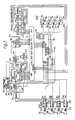
- Figure 2 is a block diagram of a multiple loop-scanning circuit having much in common with that of Figure 1 but employing the timing technique explained with reference to Figure 3, and more specifically the modification last-mentioned. Digital timing is utilised.
- Figure 2 parts like to those of Figure 1 are given like reference numerals. Where circuit operation is like that of the circuit of Figure 1, a description of it will not be repeated except so far as necessary to understanding the timing arrangements of Figure 2 upon which attention will be concentrated.
- the time base period T of Figure 3 is set by a digital timer 200, i.e. based on a digital counter.
- the enabling of the timer is under the control of the microcomputer 100 through decoder 118.
- the timer has a clock input (CK) clocked from clock oscillator 122. It also has a start input 202 whereby the timer is synchronized to a given polarity transition of the loop oscillator pulses from limiter 20.
- the counter unit within timer 200 may be a pre-settable down counter set by the enable signal to a count value equivalent to 10 mS at the clock oscillator rate. Upon counting down to zero (0) the timer generates an output signal on line 204 that marks the end of the 10 mS interval.
- a 12-bit ripple counter 206 acts as a loop cycle counter and has its outputs Q o to Q 10 connected to a port 112B' of the data selector 112. Because there are 11 bits to be read rather than the 8 bits from counter 114 in Figure 1, the data selector 112 and the control exercised by the microcomputer 100 are modified to read the 11 bits in 2 bytes to suit the 8-bit capability of port 100A.
- the counter 206 is clocked at its clock input (CK) by the loop oscillator pulses supplied through AND-gate 128' whose enabling in this case is dependent on the state of the 0 11 output of counter 206 acting to provide fault indication as before and on the state of a D-latch bistable 208. Further description of the control of the counting period of the counter 206 is given below.
- the bistable 208 is used to detect the next transition of the loop oscillator pulses which corresponds to that that started the timer and which next follows the end of the timer period, i.e. the point 152 in Figure 3. In this case there will be an integral number of cycles from the start of the timer period (corresponding to point 150 in Figure 3). To this end the bistable has its clock input (CK) connected to the output of limiter 20 so as to respond to the required polarity transition. The D input of bistable 208 is connected to the output of timer 200 so that the ⁇ output of the bistable goes low on the next appropriate transition of the loop oscillator pulses following activation of the timer output.
- CK clock input
- the D input of bistable 208 is connected to the output of timer 200 so that the ⁇ output of the bistable goes low on the next appropriate transition of the loop oscillator pulses following activation of the timer output.
- the period T of Figure 3 is measured by an 8-bit ripple counter 210 controlled by an AND-gate 212 to which the clock pulses are applied.
- the gate has two enabling inputs 214 and 216 connected to the timer output 204 and the ⁇ output of bistable 208. These outputs control the gate to transmit clock pulses to the clock input (CK) of counter 210 for the interval T defined as being the period between the activation of the timer output and the setting of the bistable. Consequently a count value representing T is established in counter 210 for transfer into the microcomputer.
- the clocking of the loop cycle counter 206 has been described but not the start and termination of the count.
- the start is controlled by the microcomputer issuing a master reset signal (MR) from port 100B to the timer 200 and counters 206 and 210 and then enabling the timer. Synchronization could be achieved by having the AND-gate 128' controlled by a signal from the timer consequent upon the receipt of an appropriate loop oscillator pulse transition at the start input.
- MR master reset signal
- a better arrangement is to control the gate 128' in dependence upon the output of bistable 208 as indicated by dashed line connection 220.
- the counter 206 will cease counting at a time corresponding to the point 152 in Figure 3. This represents the duration of (m+1) cycles as defined with reference to Figure 3.
- the period (T+ ⁇ ) is precisely that of these (n1+1) cycles and the loop oscillator period is accurately calculable from the known T together with the measured T and (n1+ 1) from counters 210 and 206 respectively.
- the general sequence of sampling is as described with reference to Figure 1.
- a small delay is preferably provided to allow the enabled oscillator to settle.
- the values in counters 206 and 210 are transferred to the microcomputer for analysis during the sampling period of the next oscillator.
- the timing function of the external timer 200 can be performed instead by software.
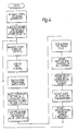
- Figure 4 provides a flow diagram of the embodiment of Figure 1
- Figure 5 provides a flow diagram of the embodiment of Figures 2 and 3.
Landscapes
- Physics & Mathematics (AREA)
- General Physics & Mathematics (AREA)
- Measurement Of Unknown Time Intervals (AREA)
Claims (16)
Applications Claiming Priority (2)
| Application Number | Priority Date | Filing Date | Title |
|---|---|---|---|
| GB8223409 | 1982-08-13 | ||
| GB8223409 | 1982-08-13 |
Publications (2)
| Publication Number | Publication Date |
|---|---|
| EP0103393A1 EP0103393A1 (fr) | 1984-03-21 |
| EP0103393B1 true EP0103393B1 (fr) | 1987-11-11 |
Family
ID=10532305
Family Applications (1)
| Application Number | Title | Priority Date | Filing Date |
|---|---|---|---|
| EP83304551A Expired EP0103393B1 (fr) | 1982-08-13 | 1983-08-05 | Détecteur de véhicule à boucle inductive |
Country Status (5)
| Country | Link |
|---|---|
| US (1) | US4668951A (fr) |
| EP (1) | EP0103393B1 (fr) |
| AU (1) | AU555872B2 (fr) |
| DE (1) | DE3374471D1 (fr) |
| ZA (1) | ZA835917B (fr) |
Families Citing this family (22)
| Publication number | Priority date | Publication date | Assignee | Title |
|---|---|---|---|---|
| AU575409B2 (en) * | 1984-06-29 | 1988-07-28 | Adt Services Ag | Frequency measuring device |
| GB8422277D0 (en) * | 1984-09-04 | 1984-10-10 | Bartlett D | Fixed frequency detector |
| US5028921A (en) * | 1987-07-27 | 1991-07-02 | Detector Systems, Inc. | Vehicle detector method and system |
| US5396234A (en) * | 1989-03-10 | 1995-03-07 | Gebert; Franz J. | Validation checking in traffic monitoring equipment |
| GB8909187D0 (en) * | 1989-04-21 | 1989-06-07 | Wiggin A J | Programmable inductive loop detector |
| EP0419273B1 (fr) * | 1989-09-21 | 1994-11-30 | Sarasota Automation Limited | Détecteur de véhicule à boucle inductrice |
| US5361064A (en) * | 1991-06-17 | 1994-11-01 | Minnesota Mining And Manufacturing Company | Vehicle detector with power main noise compensation |
| US5153525A (en) * | 1991-06-17 | 1992-10-06 | Minnesota Mining And Manufacturing Company | Vehicle detector with series resonant oscillator drive |
| AU650973B2 (en) * | 1991-06-17 | 1994-07-07 | Minnesota Mining And Manufacturing Company | Vehicle detector with environmental adaptation |
| US5239209A (en) * | 1991-06-17 | 1993-08-24 | Minnesota Mining And Manufacturing Company | Zero crossing detection circuit |
| US5281965A (en) * | 1991-06-17 | 1994-01-25 | Minnesota Mining And Manufacturing Company | Vehicle detector measurement frame segmentation |
| CA2072900A1 (fr) * | 1991-07-12 | 1993-01-13 | Earl B. Hoekman | Detecteur de vehicule avec reglage automatique de la sensibilite |
| US5491475A (en) * | 1993-03-19 | 1996-02-13 | Honeywell Inc. | Magnetometer vehicle detector |
| US5523753A (en) * | 1994-09-12 | 1996-06-04 | Minnesota Mining And Manufacturing Company | Vehicle detector system with periodic source filtering |
| US5751225A (en) * | 1994-09-12 | 1998-05-12 | Minnesota Mining And Manufacturing Company | Vehicle detector system with presence mode counting |
| US6087964A (en) * | 1997-04-24 | 2000-07-11 | Reno A & E | Vehicle detector with operational display |
| US7026955B2 (en) * | 2001-07-12 | 2006-04-11 | Scott Kauffman | Apparatus and method for activating an inductance loop vehicle detection system |
| US7132959B2 (en) | 2003-03-05 | 2006-11-07 | Diablo Controls, Inc. | Non-interfering vehicle detection |
| CN104155645B (zh) * | 2014-08-07 | 2017-02-22 | 深圳市博德维环境技术有限公司 | 车辆位置探测方法和车辆位置探测系统 |
| US10433136B2 (en) * | 2017-06-28 | 2019-10-01 | At&T Intellectual Property I, L.P. | Wireless network enhancements via inductance loops as antennas |
| CN113053003B (zh) * | 2021-03-10 | 2022-08-05 | 广东博智林机器人有限公司 | 一种车辆门禁系统及其控制方法、装置、存储介质 |
| CN113888896A (zh) * | 2021-09-30 | 2022-01-04 | 深圳市捷顺科技实业股份有限公司 | 一种闸杆控制方法、装置、设备及计算机可读存储介质 |
Family Cites Families (5)
| Publication number | Priority date | Publication date | Assignee | Title |
|---|---|---|---|---|
| US3868626A (en) * | 1973-07-09 | 1975-02-25 | Gulf & Western Industries | Digital loop detector system |
| US3989932A (en) * | 1974-02-21 | 1976-11-02 | Canoga Controls Corporation | Inductive loop vehicle detector |
| US3943339A (en) * | 1974-04-29 | 1976-03-09 | Canoga Controls Corporation | Inductive loop detector system |
| GB1588531A (en) * | 1977-01-11 | 1981-04-23 | Redland Automation Ltd | Vehicle detection |
| US4491841A (en) * | 1981-04-03 | 1985-01-01 | Sarasota Automation Limited | Self-adjusting inductive object-presence detector |
-
1983
- 1983-08-05 EP EP83304551A patent/EP0103393B1/fr not_active Expired
- 1983-08-05 DE DE8383304551T patent/DE3374471D1/de not_active Expired
- 1983-08-10 AU AU17861/83A patent/AU555872B2/en not_active Ceased
- 1983-08-10 US US06/521,814 patent/US4668951A/en not_active Expired - Lifetime
- 1983-08-11 ZA ZA835917A patent/ZA835917B/xx unknown
Also Published As
| Publication number | Publication date |
|---|---|
| US4668951A (en) | 1987-05-26 |
| ZA835917B (en) | 1984-09-26 |
| AU555872B2 (en) | 1986-10-16 |
| DE3374471D1 (en) | 1987-12-23 |
| EP0103393A1 (fr) | 1984-03-21 |
| AU1786183A (en) | 1984-02-16 |
Similar Documents
| Publication | Publication Date | Title |
|---|---|---|
| EP0103393B1 (fr) | Détecteur de véhicule à boucle inductive | |
| US3989932A (en) | Inductive loop vehicle detector | |
| EP0244052B1 (fr) | Circuit de base de temps de balayage programmable | |
| US4142238A (en) | Monitoring system | |
| US4381481A (en) | Control circuit for a stepping motor in battery-operated instruments | |
| US3710373A (en) | Signal discriminating system | |
| WO1993024996A1 (fr) | Systeme d'etalonnage automatique pour un generateur de tension de rampe | |
| RU2138829C1 (ru) | Устройство для контроля частоты | |
| EP1709740B1 (fr) | Systeme et procede de commande du declenchement d'un triac | |
| JPH04259873A (ja) | 距離判定装置 | |
| US5565750A (en) | Apparatus for applying field excitation to a synchronous electric motor | |
| US5119347A (en) | Method and timing device for measuring time intervals | |
| SU1626247A1 (ru) | Измеритель длительности переходного процесса | |
| US6072338A (en) | Method of and device for determining pulse width | |
| SU1352448A1 (ru) | Устройство дл измерени длительности импульсов | |
| EP0087874A2 (fr) | Dispositif et procédé pour produire des signaux de prédéclenchement et de déclenchement | |
| WO1992018358A1 (fr) | Systeme de commande pour essuie-glace | |
| SU1601736A1 (ru) | Цифровой генератор качающейс частоты | |
| SU1358063A1 (ru) | Цифровой фазочастотный компаратор | |
| CA1065033A (fr) | Detecteur de vehicule avec boucle d'induction | |
| SU1330615A1 (ru) | Устройство дл регулировани испытательного переменного напр жени | |
| SU591769A1 (ru) | Устройство дл контрол скорости вращени | |
| SU1508193A1 (ru) | Устройство дл циклового программного управлени | |
| SU1758279A1 (ru) | Устройство измерени времени ограничени тока транзисторными коммутаторами систем зажигани | |
| SU1041994A1 (ru) | Устройство дл контрол срабатывани электромагнитов |
Legal Events
| Date | Code | Title | Description |
|---|---|---|---|
| PUAI | Public reference made under article 153(3) epc to a published international application that has entered the european phase |
Free format text: ORIGINAL CODE: 0009012 |
|
| AK | Designated contracting states |
Designated state(s): BE DE FR GB IT NL |
|
| 17P | Request for examination filed |
Effective date: 19840824 |
|
| RAP1 | Party data changed (applicant data changed or rights of an application transferred) |
Owner name: SARASOTA AUTOMATION LIMITED |
|
| GRAA | (expected) grant |
Free format text: ORIGINAL CODE: 0009210 |
|
| AK | Designated contracting states |
Kind code of ref document: B1 Designated state(s): BE DE FR GB IT NL |
|
| REF | Corresponds to: |
Ref document number: 3374471 Country of ref document: DE Date of ref document: 19871223 |
|
| ET | Fr: translation filed | ||
| ITF | It: translation for a ep patent filed | ||
| PLBE | No opposition filed within time limit |
Free format text: ORIGINAL CODE: 0009261 |
|
| STAA | Information on the status of an ep patent application or granted ep patent |
Free format text: STATUS: NO OPPOSITION FILED WITHIN TIME LIMIT |
|
| 26N | No opposition filed | ||
| ITTA | It: last paid annual fee | ||
| PGFP | Annual fee paid to national office [announced via postgrant information from national office to epo] |
Ref country code: DE Payment date: 19980817 Year of fee payment: 16 |
|
| PG25 | Lapsed in a contracting state [announced via postgrant information from national office to epo] |
Ref country code: DE Free format text: LAPSE BECAUSE OF NON-PAYMENT OF DUE FEES Effective date: 20000601 |
|
| PGFP | Annual fee paid to national office [announced via postgrant information from national office to epo] |
Ref country code: GB Payment date: 20000802 Year of fee payment: 18 |
|
| PGFP | Annual fee paid to national office [announced via postgrant information from national office to epo] |
Ref country code: FR Payment date: 20000811 Year of fee payment: 18 |
|
| PGFP | Annual fee paid to national office [announced via postgrant information from national office to epo] |
Ref country code: NL Payment date: 20000831 Year of fee payment: 18 |
|
| PGFP | Annual fee paid to national office [announced via postgrant information from national office to epo] |
Ref country code: BE Payment date: 20001025 Year of fee payment: 18 |
|
| REG | Reference to a national code |
Ref country code: FR Ref legal event code: CD Ref country code: FR Ref legal event code: CA |
|
| REG | Reference to a national code |
Ref country code: GB Ref legal event code: 732E |
|
| PG25 | Lapsed in a contracting state [announced via postgrant information from national office to epo] |
Ref country code: GB Free format text: LAPSE BECAUSE OF NON-PAYMENT OF DUE FEES Effective date: 20010805 |
|
| PG25 | Lapsed in a contracting state [announced via postgrant information from national office to epo] |
Ref country code: BE Free format text: LAPSE BECAUSE OF NON-PAYMENT OF DUE FEES Effective date: 20010831 |
|
| REG | Reference to a national code |
Ref country code: GB Ref legal event code: 732E |
|
| BERE | Be: lapsed |
Owner name: SARASOTA AUTOMATION LTD Effective date: 20010831 |
|
| PG25 | Lapsed in a contracting state [announced via postgrant information from national office to epo] |
Ref country code: NL Free format text: LAPSE BECAUSE OF NON-PAYMENT OF DUE FEES Effective date: 20020301 |
|
| REG | Reference to a national code |
Ref country code: FR Ref legal event code: TP |
|
| GBPC | Gb: european patent ceased through non-payment of renewal fee |
Effective date: 20010805 |
|
| PG25 | Lapsed in a contracting state [announced via postgrant information from national office to epo] |
Ref country code: FR Free format text: LAPSE BECAUSE OF NON-PAYMENT OF DUE FEES Effective date: 20020430 |
|
| NLV4 | Nl: lapsed or anulled due to non-payment of the annual fee |
Effective date: 20020301 |
|
| REG | Reference to a national code |
Ref country code: FR Ref legal event code: ST |