EP0103454A1 - Parafoudre isolateur - Google Patents
Parafoudre isolateur Download PDFInfo
- Publication number
- EP0103454A1 EP0103454A1 EP83305169A EP83305169A EP0103454A1 EP 0103454 A1 EP0103454 A1 EP 0103454A1 EP 83305169 A EP83305169 A EP 83305169A EP 83305169 A EP83305169 A EP 83305169A EP 0103454 A1 EP0103454 A1 EP 0103454A1
- Authority
- EP
- European Patent Office
- Prior art keywords
- insulator
- lightning arrester
- adhesive agent
- resistor
- voltage non
- Prior art date
- Legal status (The legal status is an assumption and is not a legal conclusion. Google has not performed a legal analysis and makes no representation as to the accuracy of the status listed.)
- Granted
Links
Images
Classifications
-
- H—ELECTRICITY
- H01—ELECTRIC ELEMENTS
- H01C—RESISTORS
- H01C7/00—Non-adjustable resistors formed as one or more layers or coatings; Non-adjustable resistors made from powdered conducting material or powdered semi-conducting material with or without insulating material
- H01C7/10—Non-adjustable resistors formed as one or more layers or coatings; Non-adjustable resistors made from powdered conducting material or powdered semi-conducting material with or without insulating material voltage responsive, i.e. varistors
- H01C7/12—Overvoltage protection resistors; Arresters
-
- H—ELECTRICITY
- H01—ELECTRIC ELEMENTS
- H01T—SPARK GAPS; OVERVOLTAGE ARRESTERS USING SPARK GAPS; SPARKING PLUGS; CORONA DEVICES; GENERATING IONS TO BE INTRODUCED INTO NON-ENCLOSED GASES
- H01T4/00—Overvoltage arresters using spark gaps
- H01T4/02—Details
Definitions
- This invention relates to a lightning arrester insulator in which a voltage non-linear resistor having a major constituent of zinc oxide (ZnO) is integrally fixed in the insulator with an inorganic adhesive agent.
- ZnO zinc oxide
- This known type of voltage non-linear resistor having a major constituent of ZnO has been improved in its characteristic of resistance to deterioration by using a method wherein, as described in the above-identified prior publications, an intermediate layer of an inorganic adhesive agent such as cement or glass is interposed between the resistor and the inner surface of the insulator to reduce a surface area of the resistor contacting the surrounding air, in view of the fact that a resistance value of the resistor is gradually decreased under a reaction with a moisture contained in a small amount in the air and that a quantity of heat generated from the resistor is gradually increased, thereby producing a possibility of rupture of the insulator or other components.
- an intermediate layer of an inorganic adhesive agent such as cement or glass
- a lightning arrester insulator in which a voltage non-linear resistor having a major constituent of ZnO is integrally fixed in a longitudinal bore of the insulator through a layer of an inorganic adhesive agent which is interposed between an outer surface of the resistor and an inner wall surface of the insulator defining the longitudinal bore.
- a contact angle 6 of the inorganic adhesive agent layer defined by each end face thereof and an associated end part of the inner wall surface of the insulator is held within a range of 10° to 60°.
- the voltage non-linear resistor is buried in the insulator, that is, each end surface of the resistor is spaced from the corresponding end of the adhesive agent layer axially inwardly along the longitudinal centerline of the longitudinal bore.
- the present invention is based on the findings and results of several studies made to investigate why the lightning arrester insulator in which a voltage non-linear resistor having a major constituent of ZnO is damged by a thermal stress applied during manufacture or operation thereof, and to seek the structure which is suitable to protect the insulator against such damage.
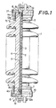
- a lightning arrester insulator of the invention wherein a plurality of voltage non-linear resistors 2 each having a major constituent of zinc oxide (ZnO) and containing small amounts of additives and impurities such as Bi 2 0 3 , Sb 2 O 3 , CaO and MgO and the like, are stacked or superposed one on another in a pile in a longitudinal bore formed in an insulator 1 made of porcelain or the like.
- An electrically conductive paste 3 such as silver or the like is used to bond adjacent ones of the voltage non-linear resistors 2.
- adheresive layer 5 a layer of an inorganic adhesive agent 5 (hereinafter referred to as "adhesive layer 5") made of glass material having a melting point of 350 to 800°C, preferably 400 to 650°C, is formed between the stack of voltage non-linear resistors 2 and the inner wall surface 4 within the body of the insulator 1 so as to constitute an integrally fixed assembly of the insulator 1 and the voltage non-linear resistors 2.
- Contact angles 8 at which both end faces of the inorganic adhesive layer 5 contact inner surfaces 4a and 4b of the insulator 1 at corresponding ends thereof, are selected to be within a range of 10° to 60° inclusive, preferably 15° to 40° inclusive.
- each end face 6 of the adhesive agent layer 5 cooperates with the associated end part 4a, 4b of the inner wall surface 4 of the insulator 1 to define the contact angle 8.
- each end surface 7 of the stack of voltage non-linear resistors 2 is spaced axially inwardly of the insulator 1 from the corresponding end face or tip 6 of the adhesive layer 5 contacting the inner wall surface 4a, 4b at the respective end part of the insulator 1, preferably by more than 10 mm, along the longitudinal centerline of the longitudinal bore.
- Metal fittings 8 as in the form of a metal flange or cap are fixed to both ends of the insulator 1 with cement 9 and electrically connected to the end surfaces 7 of the stack of voltage non-linear resistors 2 through, for example, springs 10.
- the contact angles ⁇ between the adhesive layer 5 and the inner wall surfaces 4a and 4b at the end parts of the insulator 1 are adapted to fall within the above indicated range of 10 to 60 degrees by chamfering the end portion of the inner wall of the insulator to form an inclined surface 12a with respect to the end surface 11 of the insulator as shown at the upper end of the embodiment shown in Fig. 1.
- the angular arrangement may be made in such a way, as shown at the lower end of Fig.
- the inner wall surface 4b at the end part of the insulator 1 remains to be a vertical straight surface while the opposite circumferential surface of support means 13 for the voltage non-linear resistors 2 is angled or inclined with respect to the inner wall surface 4b to form a desired angle ⁇ within the specified range. It is also possible to combine the above two arrangements to establish the angular relationship. When a support like the support means 13 is not used, the desired contact angle ⁇ may be obtained by inclining the opposite outer circumferential surface of the resistor at the bottom of the stack of resistors 2.
- At least one of the end face of the adhesive layer and the associated end part of the inner wall surface be inclined with respect to the longitudinal centerline of the longitudinal bore to form the contact angle 6 at the opposite ends of the insulator, and that the contact angle 6 be held within the range of 10° to 60°, preferably 15° to 40°.
- the stack of the non-linear resistors 2 is supported at its bottom by the support means 13 as described above, and the top end thereof may be provided with an upper support frame 15 having the same diameter as that.of the resistor 2.
- an inner corner part 14 of the adhesive layer 5 projecting axially outwardly from the end surface 7 of the resistor 2 is chamfered, preferably formed as a part-spherical surface in order to prevent concentration of thermal stress on said corner part.
- the angular range of 10-60 degrees of the contact angle 8 of the adhesive layer 5 to the inner wall surface 4a (4b) at the end part of the insulator 1, has been determined in view of the facts that, as hereinafter described in association with the following preferred embodiments, undesirable cracks are produced due to a thermal stress if the contact angle 6 is lower than 10° or higher than 60°. Further, the spaced-apart arrangement of the end surface 7 of the voltage non-linear resistor 2 and the end face or tip 6 of the inorganic adhesive layer 5 is preferred to minimize chances of cracks caused by a thermal stress.
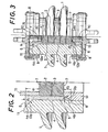
- Porcelain insulators 1 having an inner diameter of 72 mm, barrel diameter of 122 mm, shed diameter of 192 mm and a length of 120 mm were cut at their upper end part to provide an inclinded annular surface 12a, as shown in Fig. 2, an angle ⁇ 1 thereof being 10°, 15°, 20°, 30°, 40°, 50° and 60°, respectively with respect to the end face 11, i.e., to the end face 6 of the adhesive layer 6.
- an electrically conductive silver paste 3 (made by Engelhard Mineral & chemicals Corporation; Model A-2735) was applied to both surfaces of each voltage non-linear resistor 2 having a major constituent of ZnO with diemater-height sizes of 56 mm x 24 mm.
- Two resistors 2 were joined together with the paste 3, dried, and left in the air for one hour at a maximum temperature of 550°C.
- the two voltage non-linear resistors 2 were firmly bonded to each other into an integral assembly in advance.
- Support means 13 was used for supporting the voltage non-linear resistors 2 and blocking a downward flow of the adhesive agent 5 composed of glass of low melting point.
- the support means 13 was made of the same porcelain material as that of the insulator 1.
- a plurality of the support means 13 were cut at the outer circumferential surface to provide an inclined surface 12b so that a contact angle 6 2 of the end face of the adhesive layer 5 to the inner surface 4b was 10° , 15° , 20°, 30°, 40°, 50° and 60°, respectively.
- an upper supporting frame 15 having an outer diameter of 56 mm, inner diameter of 40 mm and a height of 40 mm was prepared in plurality.
- Each frame 15 was made of the same porcelain material as that of the insulator 1.
- the voltage non-linear resistor assembly 2 mounted on the supporting means 13 was placed in the central bore of the insulator 1, and the upper supporting frame 15 was mounted on the top of the resistor assembly 2.
- the adhesive agent 5 i.e., a glass having a low melting point of 470°C was heated in the air to 490 °C and poured into a space defined by the support means 13, non-linear resistor assembly 2, upper support frame 15 and inner wall surface 4 of the insulator 1, and then cooled to obtain an assembled unit of the lightning arrester insulator of the present invention.
- Samples Nos. 1 through 19 were prepared.
- a spacing depth di from the uppoer end face 6 of the solidified inorganic adhesive layer 5 to the upper end surface 7 of the voltage non-linear resistor 2 is 30 mm and a depth d 2 between the lower end surface 7 and the lower tip 6 is 15 mm.
- An insulator, voltage non-linear resistor having a major constituent of Z nO, support means, upper support frame and adhesive agent of low melting glass, similar to those used in Example 1 were employed while sizes of the support means and upper support frame were varied to change the spacing depths d 1 , d 2 between the end surface of the resistor and the end face or tip of the adhesive layer.
- the upper spacing depth di and lower spacing depth d 2 were set to the sizes shown in Table 2. Fittings were cemented to both ends of the insulator to provide a lightning arrester insulators of the present invention, which are designated as Samples Nos. 32 through 59. These lightning arrester insulators were cooled and heated alternately ten times of cycling in the same manner as in Example 1. The insulators were checked for cracks, but no cracks were found in any of the insulators.
- One end of the porcelain insulators each having an inner diameter of 64 mm, barrel diameter of 144 mm, shed diameter of 244 mm and a length of 210 mm was cut to form an inclined surface 4a, as shown in Fig. 3, which is slant at a contact angle ⁇ 1 of 10° , 15° , 20° , 30°, 40°, 50° and 60°, respectively with respect to the upper end face 11 of the insulator.
- the outer circumferential surface of the support means 13 for the resistors 2 was cut to form an inclined surface 12b such that the angle 6 2 of contact with the lower end face of the adhesive layer 5 was 30°.
- the spacing depth d 2 from the lower tip 6 of the resistor 2 was set to 15 mm and the entire height of the support means was selected to be 50 mm.
- the thus machined insulators 1 and support means 13, and a stack of voltage non-linear resistors 2 were assembled to produce the insulators of the invention.
- the voltage non-linear resistor assembly 2 was constructed such that the individual non-linear resistors 2 each having a major constituent of ZnO with 56 mm diameter and 24 mm height were bonded in a stack with silver conductive paste 3 (made by Engelhard Minerals & Chemicals Corporation; Model A-2735) applied to adjacent surfaces of the resistors 2. Thereafter, they were left in the air for one hour at a maximum temperature of 550 °C. Thus, a plurality of voltage non-linear resistors 2 were integrated into a firmly bonded assembly.
- VlmADC DC voltage required for a flow of DC current of 1 mA which is generally used as an index of an electric characteristic of the voltage non-linear resistor 2 and which corresponds to a rise voltage in V-I characteristic of the resistor 2 (hereinafter simply called "V lmA DC”), was found to be in a range of 20.4 kV to 21.3 kV.
- Fixing fittings 8 were fixed to both ends of the insulator 1 with cement 9, and each of seven kinds of lightening arrester insulators of the present invention in which the voltage non-linear resistors 2 having a major constituent of ZnO were integrally fixed in the insulator 1 with adhesive agent 5 of inorganic glass.
- Samples Nos. 1 through 7 were prepared.
- the products having the angular dimensions outside the specified range of the invention were prepared as comparative products designated as Samples Nos. 8 through 10. Also prepared was Sample No. 11 having contact angles 8 1 and 8 2 of 90°. Samples 8, 10 and 11 of these products demonstrated some cracks during their firing and a decrease in value of V lmA DC.
- the lightning arrester insulators with no cracks generated during its firing operations were immersed alternately in hot water of 60°C and methyl alcohol cooled to -40°C with dry ice, each for four hours. This heating and cooling cycle was repeated ten times. The products were observed for cracks with a dyeing method, and a value of V lmA DC thereof was measured.
- the products of the present invention demonstrated no cracks during their firing, heating and coling tests as well as their electric discharge duration test, and it was noted in particular that the lightning arrester insulators (Samples Nos. 2 through 5) having a contact angle between the porcelain and the adhesive layer of 15° to 40° showed an excellent heat resistance characteristic.
- the lightning arrester insulator of the present invention may be used as a stable lightning arrester insulator for a long period of time permitting protection of various kinds of power plant facilities and substations against an excessive flow of curret or surge caused by a lightning.
- This is accomplished with a simple structure wherein a contact angle 6 of the inorganic adhesive layer with respect to the inner wall surface at opposite ends of the insulator is kept within a range of 10° to 60° .
- Such arrangement protects the insulator against damage due to a thermal stress during manufacture, or upon the occurrence of a lightning or other surge.
- the lightning arrester insulator of the present invention is extremely useful and effective in its industrial application.
Landscapes
- Engineering & Computer Science (AREA)
- Microelectronics & Electronic Packaging (AREA)
- Physics & Mathematics (AREA)
- Electromagnetism (AREA)
- Thermistors And Varistors (AREA)
- Insulators (AREA)
Applications Claiming Priority (2)
| Application Number | Priority Date | Filing Date | Title |
|---|---|---|---|
| JP160555/82 | 1982-09-14 | ||
| JP57160555A JPS5949178A (ja) | 1982-09-14 | 1982-09-14 | 避雷碍子 |
Publications (2)
| Publication Number | Publication Date |
|---|---|
| EP0103454A1 true EP0103454A1 (fr) | 1984-03-21 |
| EP0103454B1 EP0103454B1 (fr) | 1987-07-08 |
Family
ID=15717518
Family Applications (1)
| Application Number | Title | Priority Date | Filing Date |
|---|---|---|---|
| EP83305169A Expired EP0103454B1 (fr) | 1982-09-14 | 1983-09-06 | Parafoudre isolateur |
Country Status (6)
| Country | Link |
|---|---|
| US (1) | US4571660A (fr) |
| EP (1) | EP0103454B1 (fr) |
| JP (1) | JPS5949178A (fr) |
| CA (1) | CA1213640A (fr) |
| DE (1) | DE3372423D1 (fr) |
| IN (1) | IN161476B (fr) |
Cited By (3)
| Publication number | Priority date | Publication date | Assignee | Title |
|---|---|---|---|---|
| EP0269195A1 (fr) * | 1986-11-27 | 1988-06-01 | Ngk Insulators, Ltd. | Isolateur de parafoudre |
| EP0443178A3 (en) * | 1990-02-23 | 1992-10-21 | Amerace Corporation (A Delaware Corporation) | Surge arrester with rigid insulating housing |
| US5896266A (en) * | 1996-12-06 | 1999-04-20 | Asea Brown Boveri Ag | Overvoltage suppressor having insulating housing |
Families Citing this family (13)
| Publication number | Priority date | Publication date | Assignee | Title |
|---|---|---|---|---|
| GB8602112D0 (en) * | 1986-01-29 | 1986-03-05 | Bowthorpe Emp Ltd | Electrical surge arrester/diverter |
| CA1315336C (fr) * | 1986-01-29 | 1993-03-30 | Rodney Meredith Doone | Dispositif de protection contre les surtensions |
| US4803588A (en) * | 1986-04-14 | 1989-02-07 | Cooper Industries, Inc. | Surge arrester |
| JPS62264585A (ja) * | 1986-05-09 | 1987-11-17 | 中部電力株式会社 | 避雷器内蔵カツトアウト |
| JPH0642345B2 (ja) * | 1986-09-16 | 1994-06-01 | 中部電力株式会社 | 耐雷カットアウト |
| JPH0727794B2 (ja) * | 1986-09-16 | 1995-03-29 | 中部電力株式会社 | 避雷器 |
| JPH0518866Y2 (fr) * | 1986-09-26 | 1993-05-19 | ||
| JP2711096B2 (ja) * | 1987-06-15 | 1998-02-10 | 日本高圧電気株式会社 | アレスター内蔵形高圧カットアウト |
| US5402100A (en) * | 1993-12-06 | 1995-03-28 | General Electric Company | Overvoltage surge arrester with means for protecting its porcelain housing against rupture by arc-produced shocks |
| JP4342078B2 (ja) * | 2000-04-07 | 2009-10-14 | 株式会社東芝 | 避雷器 |
| USD816612S1 (en) * | 2016-02-18 | 2018-05-01 | Fujikura Ltd. | Polymer insulator |
| US10741313B1 (en) * | 2019-02-06 | 2020-08-11 | Eaton Intelligent Power Limited | Bus bar assembly with integrated surge arrestor |
| CN113300346B (zh) * | 2021-04-21 | 2024-10-22 | 国网冀北电力有限公司电力科学研究院 | 一种限压装置及其安装方法 |
Citations (2)
| Publication number | Priority date | Publication date | Assignee | Title |
|---|---|---|---|---|
| GB764693A (en) * | 1954-01-06 | 1957-01-02 | E M P Electric Ltd | Improvements in non-linear resistor elements for lightning arresters |
| FR2441907A1 (fr) * | 1978-11-15 | 1980-06-13 | Electric Power Res Inst | Limiteur de tension de type ferme |
Family Cites Families (2)
| Publication number | Priority date | Publication date | Assignee | Title |
|---|---|---|---|---|
| US3549791A (en) * | 1968-05-29 | 1970-12-22 | Joslyn Mfg & Supply Co | Protected rod insulator with soft elastomer filler |
| US4315699A (en) * | 1975-05-12 | 1982-02-16 | Joslyn Mfg. And Supply Co. | Multiwedge connector |
-
1982
- 1982-09-14 JP JP57160555A patent/JPS5949178A/ja active Granted
-
1983
- 1983-08-31 US US06/528,032 patent/US4571660A/en not_active Expired - Lifetime
- 1983-09-05 IN IN1078/CAL/83A patent/IN161476B/en unknown
- 1983-09-06 EP EP83305169A patent/EP0103454B1/fr not_active Expired
- 1983-09-06 DE DE8383305169T patent/DE3372423D1/de not_active Expired
- 1983-09-13 CA CA000436580A patent/CA1213640A/fr not_active Expired
Patent Citations (2)
| Publication number | Priority date | Publication date | Assignee | Title |
|---|---|---|---|---|
| GB764693A (en) * | 1954-01-06 | 1957-01-02 | E M P Electric Ltd | Improvements in non-linear resistor elements for lightning arresters |
| FR2441907A1 (fr) * | 1978-11-15 | 1980-06-13 | Electric Power Res Inst | Limiteur de tension de type ferme |
Non-Patent Citations (1)
| Title |
|---|
| PATENTS ABSTRACTS OF JAPAN, vol. 3, no. 145(E-155), 30th November 1979, page 105 E 155 & JP - A - 54 124 294 (MITSUBISHI DENKI K.K.) 27-09-1979 * |
Cited By (4)
| Publication number | Priority date | Publication date | Assignee | Title |
|---|---|---|---|---|
| EP0269195A1 (fr) * | 1986-11-27 | 1988-06-01 | Ngk Insulators, Ltd. | Isolateur de parafoudre |
| US4796149A (en) * | 1986-11-27 | 1989-01-03 | Ngk Insulators, Ltd. | Lightning arrestor insulator |
| EP0443178A3 (en) * | 1990-02-23 | 1992-10-21 | Amerace Corporation (A Delaware Corporation) | Surge arrester with rigid insulating housing |
| US5896266A (en) * | 1996-12-06 | 1999-04-20 | Asea Brown Boveri Ag | Overvoltage suppressor having insulating housing |
Also Published As
| Publication number | Publication date |
|---|---|
| DE3372423D1 (en) | 1987-08-13 |
| JPS5949178A (ja) | 1984-03-21 |
| JPH0142483B2 (fr) | 1989-09-13 |
| EP0103454B1 (fr) | 1987-07-08 |
| IN161476B (fr) | 1987-12-12 |
| US4571660A (en) | 1986-02-18 |
| CA1213640A (fr) | 1986-11-04 |
Similar Documents
| Publication | Publication Date | Title |
|---|---|---|
| EP0103454B1 (fr) | Parafoudre isolateur | |
| EP0125884B1 (fr) | Isolateur électrique | |
| CN100463079C (zh) | 电流-电压非线性电阻体 | |
| US3959543A (en) | Non-linear resistance surge arrester disc collar and glass composition thereof | |
| US4031498A (en) | Non-linear voltage-dependent resistor | |
| US6864432B2 (en) | Electrical insulators, materials and equipment | |
| US4218721A (en) | Heat transfer system for voltage surge arresters | |
| US6225567B1 (en) | Polymeric weathershed surge arrester and method | |
| AU2002228247A1 (en) | Electrical insulators, materials and equipment | |
| USRE29731E (en) | Metal oxide voltage-variable resistor composition | |
| US4476513A (en) | Surge arrester | |
| CA1077254A (fr) | Isolateurs electriques | |
| US5387432A (en) | Method for making metal oxide varistors coated with passivating coating | |
| EP0304203B1 (fr) | Résistance non linéaire dépendant de la tension | |
| KR910000622B1 (ko) | 피뢰기 애자 | |
| US4452729A (en) | Voltage stable nonlinear resistor containing minor amounts of aluminum and boron | |
| US3838378A (en) | Voltage-nonlinear resistors | |
| US4761707A (en) | Lightning-conducting insulators | |
| US1927894A (en) | Fused stack arrester | |
| EP0494507A1 (fr) | Varistance à l'oxyde de zinc à haute énergie | |
| Lustgarten | High-tension porcelain line insulators | |
| CA1042653A (fr) | Collier de disque d'eclateur a resistance non-lineaire et composition du verre | |
| CA1131297A (fr) | Dispositif de transfert de chaleur pour limiteurs de surtensions | |
| KR830000850Y1 (ko) | 산화아연 피뢰기 | |
| JPS6331903B2 (fr) |
Legal Events
| Date | Code | Title | Description |
|---|---|---|---|
| PUAI | Public reference made under article 153(3) epc to a published international application that has entered the european phase |
Free format text: ORIGINAL CODE: 0009012 |
|
| 17P | Request for examination filed |
Effective date: 19831022 |
|
| AK | Designated contracting states |
Designated state(s): BE CH DE FR GB IT LI SE |
|
| GRAA | (expected) grant |
Free format text: ORIGINAL CODE: 0009210 |
|
| AK | Designated contracting states |
Kind code of ref document: B1 Designated state(s): BE CH DE FR GB IT LI SE |
|
| REF | Corresponds to: |
Ref document number: 3372423 Country of ref document: DE Date of ref document: 19870813 |
|
| ET | Fr: translation filed | ||
| ITF | It: translation for a ep patent filed | ||
| PLBE | No opposition filed within time limit |
Free format text: ORIGINAL CODE: 0009261 |
|
| STAA | Information on the status of an ep patent application or granted ep patent |
Free format text: STATUS: NO OPPOSITION FILED WITHIN TIME LIMIT |
|
| 26N | No opposition filed | ||
| ITTA | It: last paid annual fee | ||
| EAL | Se: european patent in force in sweden |
Ref document number: 83305169.1 |
|
| REG | Reference to a national code |
Ref country code: GB Ref legal event code: IF02 |
|
| PGFP | Annual fee paid to national office [announced via postgrant information from national office to epo] |
Ref country code: GB Payment date: 20020827 Year of fee payment: 20 |
|
| PGFP | Annual fee paid to national office [announced via postgrant information from national office to epo] |
Ref country code: FR Payment date: 20020917 Year of fee payment: 20 Ref country code: CH Payment date: 20020917 Year of fee payment: 20 |
|
| PGFP | Annual fee paid to national office [announced via postgrant information from national office to epo] |
Ref country code: BE Payment date: 20020918 Year of fee payment: 20 |
|
| PGFP | Annual fee paid to national office [announced via postgrant information from national office to epo] |
Ref country code: SE Payment date: 20020923 Year of fee payment: 20 Ref country code: DE Payment date: 20020923 Year of fee payment: 20 |
|
| PG25 | Lapsed in a contracting state [announced via postgrant information from national office to epo] |
Ref country code: LI Free format text: LAPSE BECAUSE OF EXPIRATION OF PROTECTION Effective date: 20030905 Ref country code: GB Free format text: LAPSE BECAUSE OF EXPIRATION OF PROTECTION Effective date: 20030905 Ref country code: CH Free format text: LAPSE BECAUSE OF EXPIRATION OF PROTECTION Effective date: 20030905 |
|
| BE20 | Be: patent expired |
Owner name: *NGK INSULATORS LTD Effective date: 20030906 Owner name: *MITSUBISHI DENKI K.K. Effective date: 20030906 Owner name: *CHUBU ELECTRIC POWER CY INC. Effective date: 20030906 |
|
| REG | Reference to a national code |
Ref country code: CH Ref legal event code: PL |
|
| REG | Reference to a national code |
Ref country code: GB Ref legal event code: PE20 |
|
| EUG | Se: european patent has lapsed |