EP0103590B1 - Prosthetic foot - Google Patents
Prosthetic foot Download PDFInfo
- Publication number
- EP0103590B1 EP0103590B1 EP83900814A EP83900814A EP0103590B1 EP 0103590 B1 EP0103590 B1 EP 0103590B1 EP 83900814 A EP83900814 A EP 83900814A EP 83900814 A EP83900814 A EP 83900814A EP 0103590 B1 EP0103590 B1 EP 0103590B1
- Authority
- EP
- European Patent Office
- Prior art keywords
- hollow core
- prosthetic foot
- adapter
- foot
- core
- Prior art date
- Legal status (The legal status is an assumption and is not a legal conclusion. Google has not performed a legal analysis and makes no representation as to the accuracy of the status listed.)
- Expired
Links
- 210000002683 foot Anatomy 0.000 claims description 67
- 239000000463 material Substances 0.000 claims description 18
- 230000033001 locomotion Effects 0.000 claims description 9
- 239000004033 plastic Substances 0.000 claims description 9
- 229920003023 plastic Polymers 0.000 claims description 9
- 210000000544 articulatio talocruralis Anatomy 0.000 claims description 6
- 210000001226 toe joint Anatomy 0.000 claims description 6
- 230000000694 effects Effects 0.000 claims description 2
- 239000011162 core material Substances 0.000 description 26
- 230000006870 function Effects 0.000 description 7
- 125000006850 spacer group Chemical group 0.000 description 7
- 210000000452 mid-foot Anatomy 0.000 description 5
- 210000003108 foot joint Anatomy 0.000 description 4
- 230000007246 mechanism Effects 0.000 description 4
- 238000000034 method Methods 0.000 description 4
- 239000006096 absorbing agent Substances 0.000 description 3
- 229920001971 elastomer Polymers 0.000 description 3
- 238000004519 manufacturing process Methods 0.000 description 3
- 230000035939 shock Effects 0.000 description 3
- 239000004743 Polypropylene Substances 0.000 description 2
- 238000005304 joining Methods 0.000 description 2
- 210000001503 joint Anatomy 0.000 description 2
- 230000037230 mobility Effects 0.000 description 2
- 238000000465 moulding Methods 0.000 description 2
- 230000005019 pattern of movement Effects 0.000 description 2
- 229920000098 polyolefin Polymers 0.000 description 2
- -1 polypropylene Polymers 0.000 description 2
- 229920001155 polypropylene Polymers 0.000 description 2
- 238000005096 rolling process Methods 0.000 description 2
- 229920000049 Carbon (fiber) Polymers 0.000 description 1
- 239000004677 Nylon Substances 0.000 description 1
- 210000003423 ankle Anatomy 0.000 description 1
- 210000000549 articulatio subtalaris Anatomy 0.000 description 1
- 238000000071 blow moulding Methods 0.000 description 1
- 239000004917 carbon fiber Substances 0.000 description 1
- 238000010276 construction Methods 0.000 description 1
- 238000001746 injection moulding Methods 0.000 description 1
- 230000008407 joint function Effects 0.000 description 1
- VNWKTOKETHGBQD-UHFFFAOYSA-N methane Chemical compound C VNWKTOKETHGBQD-UHFFFAOYSA-N 0.000 description 1
- 239000000203 mixture Substances 0.000 description 1
- 238000012986 modification Methods 0.000 description 1
- 230000004048 modification Effects 0.000 description 1
- 229920001778 nylon Polymers 0.000 description 1
- 229920001084 poly(chloroprene) Polymers 0.000 description 1
- 238000011084 recovery Methods 0.000 description 1
- 239000012858 resilient material Substances 0.000 description 1
- 230000000717 retained effect Effects 0.000 description 1
- 238000004088 simulation Methods 0.000 description 1
- 239000007787 solid Substances 0.000 description 1
- 230000007704 transition Effects 0.000 description 1
- 239000002023 wood Substances 0.000 description 1
Images

Classifications
-
- A—HUMAN NECESSITIES
- A61—MEDICAL OR VETERINARY SCIENCE; HYGIENE
- A61F—FILTERS IMPLANTABLE INTO BLOOD VESSELS; PROSTHESES; DEVICES PROVIDING PATENCY TO, OR PREVENTING COLLAPSING OF, TUBULAR STRUCTURES OF THE BODY, e.g. STENTS; ORTHOPAEDIC, NURSING OR CONTRACEPTIVE DEVICES; FOMENTATION; TREATMENT OR PROTECTION OF EYES OR EARS; BANDAGES, DRESSINGS OR ABSORBENT PADS; FIRST-AID KITS
- A61F2/00—Filters implantable into blood vessels; Prostheses, i.e. artificial substitutes or replacements for parts of the body; Appliances for connecting them with the body; Devices providing patency to, or preventing collapsing of, tubular structures of the body, e.g. stents
- A61F2/50—Prostheses not implantable in the body
- A61F2/60—Artificial legs or feet or parts thereof
- A61F2/66—Feet; Ankle joints
Definitions
- the present invention relates to a new type of prosthetic foot, i.e. an artificial substitute for a lost biological foot.
- the major problem which the invention is intended to solve is to provide a light-weight prosthetic foot which to the greatest possible extent resembles the biological foot concerning possibilities of movement and pattern of movement, effect of forces and loss of energy on walking, shape and appearance, etc., and which is also comparatively easy and cheap to manufacture and can easily be adjusted to different patients.
- prosthetic feet In the most common design of prosthetic feet there is provided a wooden core, to which an adapter for a lower leg prosthesis is attached.
- these prosthetic feet separate elastic elements are used for achieving the desired simulation of the joints and the pattern of movement of the biological foot when walking, especially the desired mobility in the ankle joint, the spring joints (e.g. subtalar joint) and the toe area on the heal strike and the push-off.
- Such constructions having a comparatively heavy core and separate foot joint mechanisms, are complex and heavy and cause considerable loss of energy on walking (the leg/leg prosthesis forms a long lever with the prosthetic foot at one end thereof).
- Swedish Patent No. 139,076 and German Patent No. 354,246 can be mentioned as examples of prior art prosthetic feet based on a heavy wooden core and suffering from the above mentioned drawbacks.
- the first mentioned patent discloses a prosthetic foot consisting of a heel and mid-foot portion, which is connected to a toe piece by means of a pair of cooperating plate springs which press the toe piece downwards.
- the heel portion is connected to a lower leg prosthesis in conventional manner by means of a ball joint and a rubber cushion.
- the latter patent discloses a different type of prosthetic foot - a so-called SACH-foot (Solid Ankle Cushion Heel) prosthesis - wherein a wedge-shaped wooden lower leg prosthesis is connected to the prosthetic foot between a wooden toe and mid-foot piece and a heel cushion of rubber, a plate spring being connected between the front foot portion and the rear part of the lower leg prosthesis for providing resilient resistance to downwards/backwards motion of the lower leg prosthesis.
- DE-A-3 137 684 discloses an artificial leg and foot, in which the prosthetic foot is connected to the prosthetic leg by means of a ball joint, and which comprises a rigid hollow support of carbon fiber material.
- Russian Patent No. 738,618 discloses an artificial foot comprising a moulded hollow heel and mid-foot piece, which is hingedly joined to a hollow toe piece.
- This artificial foot has most complex, heavy and expensive mechanisms for joining the foot to the lower leg prosthesis and providing the desired motions.
- there are multiple connections between the artificial foot and the leg prosthesis including a multitude of separate connection elements, such as a talocrural shock absorber with two telescoping sockets, a ball joint, a front shock absorber, double rear shock absorbers, rotation units, etc.
- the present invention thus aims at eliminating, or reducing, these and other drawbacks of known prostheticfeet, and to this end there is according to the invention proposed a new type of prosthetic foot, the characteristic features of which are indicated in the subsequent claims and will be explained further below.
- the prosthetic foot thus comprises a non-homogenous - or hollow - integral core which by e.g. a combination of choice of material, material thickness and shape forms a system of elastic and rigid areas, so that the core in itself forms an elastic and flexible foot joint system when connected directly to a substantially rigid foot adapter without the mediation of any separate articulated elements.
- the foot joint mechanisms (elastic elements) and the wooden core (rigid element) of the conventional prosthetic feet are thus replaced by one single, hollow, shaped body having corresponding mechanical properties.
- the hollow core is provided with means for attachment of the foot adapter substantially without the mediation of articulated elements, so that joint and supporting functions which are desired during the walking cycle are achieved by the substantially direct contact between the substantially rigid foot adapter and the hollow core.
- the direct contact between the rigid adapter and the hollow core is such that it permits movements in all directions, including lateral movements (prona- tion and supernation) and rotation movements, however with a limited mobility in the dorsal direction.
- the prosthesis according to the invention permits a "soft" dorsal stop, thereby avoiding unnecessarily great strain at the stop. As is well known the dorsal stop for a normal patient occurs when the leg/leg prosthesis has just passed the vertical line.
- the indicated properties of the hollow core are primarily determined by the choice of material, the thickness of the material and the shape of the core.
- the requirements on the material, at least after having being shaped to this core, are primarily that it shall be capable of standing the repeated deformation which the walking movement involves, i.e. have very high folding strength ("hinge properties"). Further, it should have good elastic recovery, i.e. a good plastic memory.
- a polyolefin such as polypropylene, polyolefin (polypropylene)/rubber mixtures, Hytrel ® , etc.
- the hollow core of the prosthetic foot according to the invention can be manufactured by methods which are known per se and which make it possible to provide the desired shape and, if desired, varying material thickness for the prosthetic foot to provide the desired joint and supporting functions during the walking cycle.
- One suitable such method is blow molding of plastics, and other examples of suitable methods of manufacture are rotation molding, injection molding, etc. As mentioned such methods of manufacture are per se conventional and will therefore not be described further herein.
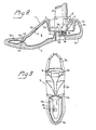
- the prosthetic foot is generally designated by the reference numeral 1.
- the foot adapter in general is referenced 2.
- the prosthetic foot 1 essentially consists of a hollow, shaped body or core 3 which is covered by a suitable covering 4, e.g. of polyure- tan.
- a suitable covering 4 e.g. of polyure- tan.
- the covering 4 primarily serves to function as a "foot sole” and for the rest to give the prosthesis foot a cosmetically attractive design.
- the core 3 consists of a comparatively thin plastic shell enclosing an inner cavity 5 which can be open or closed.
- the continuous core or skeleton 3 comprises a toe portion 3a, a mid-foot portion 3b, a heel portion 3c and an adapter attachment portion 3d.
- the transition between the mid-foot portion 3b and the toe or front foot portion 3a is, by means of a recessed portion 3e or otherwise, shaped so that it forms a "joint" corresponding to a toe joint. It is, however, within the scope of the invention to replace the toe portion 3a by any conventional toe joint device.
- the prosthetic foot 1 is attached to the foot adapter 2 by means of a bolt 6 and a washer 7, the bolt extending through the attachment portion 3d of the skeleton 3.
- the adapter 2 is in turn connected to a tubular skeleton part 8 of a lower leg prosthesis or the like (not shown) by means of a suitable fastening device 9.
- the bolt head 6 is located in a recess 10 provided in the bottom side of the skeleton, and the adapter 2 is mounted in a top side recess 11 of the plastic skeleton 3.
- the recess 11 has a substantially flat bottom 11 a having side walls 11b, 11c directed obliquely upwards.
- the adapter 2 substantially directly (from the functional viewpoint unessential washers or spacers may be present) contacts the substantially flat bottom 11a of the skeleton 3.
- the front bottom surface 13 of the adapter 2 i.e. in front of the bolt 6) is substantially planar in its contact with the bottom 11 a, whereas its rear part (i.e. behind the bolt 6) can have convex or rounded shape (as at 12, for reasons that will be explained further below).
- the function of the prosthetic foot is best explained with reference to the walking cycle heel strike - dorsal stop - toe rolling.
- the walking cycle is begun by the heel strike against the ground, and the great forces involved therein are absorbed by a thicker heel portion 4a of the sole and the heel portion 3c.
- On the heel strike it is, however, primarily essential to provide a soft ankle joint and this is achieved by cooperation between the adapter 2 and the hollow body 3, which thanks to its shape absorbs the created forces.
- the softness in the ankle joint can be controlled further by variation of the curvature of the convex portion 12 on the adapter 2: the smaller the radius, the softer the ankle joint.
- the walking step is then continued by rolling forwards to the dorsal stop, which occurs by the contact of the substantially planar front bottom surface 13 of the foot adapter with the skeleton surface 11a. Because of the elasticity of the material in the portion 11a, and in the entire skeleton body 3, the dorsal stop will not be abrupt, but will take place with a certain resilience. Thereafter the toe joint 3e turns into function, and as mentioned above the same can alternatively consist of a conventional toe joint (or simply be left out).
- FIG. 2 An alternative embodiment of the means for connecting the prosthetic foot 1 to the foot adapter 2 is shown in Fig. 2, wherein like parts as in Fig. 1 have the same reference numerals.
- two shims or spacers 15 and 16 are provided between the bolt head 6a and the flat bottom 11a a of the attachment recess 11.
- the first spacer 15 has rounded edges on the side facing the bottom 11a, and it is made of a hard material, preferably hard plastics such as nylon.
- the second spacer 16, which is located between the first spacer 15 and the bolt head (or nut) 6a is made of a resilient material, preferably a resilient plastics material such as neoprene.
- the spacer 16 provides for automatic tightening of the connection between the bolt head and the core if cold flow should occur in the materials of the core bottom 11a a and the spacer 15.
- Fig. 3 shows a preferred embodiment of the core 3 viewed from above.
- a hole 14 in the center portion of the toe joint area 3e is provided.
- the purpose of this hole is to attach the covering 4 to the core 3 in a manner such that the covering 4 is loosely provided around the core 3, however with interconnection between the covering parts 4a and 4b (Fig. 1) through the hole 14.
- This interconnection can be achieved by e.g. moulding the resilient covering 4 around the core 3 without bonding to the same, said interconnection being formed by the covering material filling the hole 14, thus forming an integral covering including a piece of material joining the covering portions 4a and 4b through the hole 14. It has been found that considerable advantages are obtained on the contact with the ground during the walking cycle when using this embodiment, wherein the covering 4 is allowed to be displaced somewhat along the core 3 (while still being retained in its general position by the interconnection through the hole 14).
Landscapes
- Health & Medical Sciences (AREA)
- Transplantation (AREA)
- Vascular Medicine (AREA)
- Life Sciences & Earth Sciences (AREA)
- Oral & Maxillofacial Surgery (AREA)
- Engineering & Computer Science (AREA)
- Biomedical Technology (AREA)
- Heart & Thoracic Surgery (AREA)
- Orthopedic Medicine & Surgery (AREA)
- Cardiology (AREA)
- Animal Behavior & Ethology (AREA)
- General Health & Medical Sciences (AREA)
- Public Health (AREA)
- Veterinary Medicine (AREA)
- Prostheses (AREA)
- Materials For Medical Uses (AREA)
Priority Applications (1)
| Application Number | Priority Date | Filing Date | Title |
|---|---|---|---|
| AT83900814T ATE22003T1 (de) | 1982-03-05 | 1983-03-03 | Fuessprothese. |
Applications Claiming Priority (2)
| Application Number | Priority Date | Filing Date | Title |
|---|---|---|---|
| SE8201389 | 1982-03-05 | ||
| SE8201389A SE8201389L (sv) | 1982-03-05 | 1982-03-05 | Protesfot |
Publications (2)
| Publication Number | Publication Date |
|---|---|
| EP0103590A1 EP0103590A1 (en) | 1984-03-28 |
| EP0103590B1 true EP0103590B1 (en) | 1986-09-10 |
Family
ID=20346178
Family Applications (1)
| Application Number | Title | Priority Date | Filing Date |
|---|---|---|---|
| EP83900814A Expired EP0103590B1 (en) | 1982-03-05 | 1983-03-03 | Prosthetic foot |
Country Status (10)
| Country | Link |
|---|---|
| US (1) | US4619661A (da) |
| EP (1) | EP0103590B1 (da) |
| JP (1) | JPS59500300A (da) |
| CA (1) | CA1198252A (da) |
| DE (1) | DE3365961D1 (da) |
| DK (1) | DK507283D0 (da) |
| FI (1) | FI833991A0 (da) |
| NO (1) | NO833990L (da) |
| SE (1) | SE8201389L (da) |
| WO (1) | WO1983003050A1 (da) |
Families Citing this family (25)
| Publication number | Priority date | Publication date | Assignee | Title |
|---|---|---|---|---|
| US5181932A (en) * | 1989-04-13 | 1993-01-26 | Phillips L Van | Foot prosthesis having auxiliary ankle construction |
| GB8605026D0 (en) * | 1986-02-28 | 1986-04-09 | Hanger & Co Ltd J E | Artificial foot |
| US4735754A (en) * | 1986-08-18 | 1988-04-05 | Horst Buckner | Method for fabricating artificial body parts |
| US5066305A (en) * | 1988-10-25 | 1991-11-19 | Model & Instrument Development Corporation | Prosthetic foot having a low profile cantilever spring keel |
| US6406500B1 (en) | 1989-04-13 | 2002-06-18 | Van L. Phillips | Foot prosthesis having curved forefoot |
| US5290319A (en) | 1991-02-28 | 1994-03-01 | Phillips L Van | Prosthetic foot incorporating adjustable bladders |
| US5514186A (en) * | 1989-04-13 | 1996-05-07 | Phillips; Van L. | Attachment construction for prosthesis |
| US5549714A (en) * | 1990-09-21 | 1996-08-27 | Phillips; Van L. | Symes foot prosthesis |
| US5181933A (en) * | 1991-02-28 | 1993-01-26 | Phillips L Van | Split foot prosthesis |
| US5314499A (en) * | 1991-04-04 | 1994-05-24 | Collier Jr Milo S | Artificial limb including a shin, ankle and foot |
| US5545234A (en) * | 1991-04-04 | 1996-08-13 | Collier, Jr.; Milo S. | Lower extremity prosthetic device |
| KR0155591B1 (ko) * | 1991-09-30 | 1998-11-16 | 반 엘 필립스 | 에너지 저장식 의족 파일론 |
| US5443528A (en) * | 1992-11-17 | 1995-08-22 | Allen; Scott | Coil spring prosthetic foot |
| US5593455A (en) * | 1994-05-27 | 1997-01-14 | Phillips; Van L. | Plug mounted prosthesis |
| SE511893C2 (sv) * | 1996-07-05 | 1999-12-13 | Pro Pel Ab | Anpassningsbar framfotsdel för en fotprotes; användning av en sådan framfotsdel i en inställbar fotprotes samt system avsett för individuellt anpassningsbara fotproteser |
| RU2124334C1 (ru) * | 1997-10-29 | 1999-01-10 | Реутовский экспериментальный завод резинотехнических изделий | Способ изготовления протеза стопы |
| UA52676C2 (uk) * | 1999-02-22 | 2003-01-15 | Науково-Іноваційна Фірма "Вол" | Протез гомілковоступневої частини ноги |
| RU2162674C2 (ru) * | 1999-05-17 | 2001-02-10 | Открытое акционерное общество "Ракетно-космическая корпорация "Энергия" им. С.П. Королева" | Пневмостопа протеза нижней конечности |
| WO2002051342A1 (en) | 2000-12-22 | 2002-07-04 | Townsend Barry W | Prosthetic foot |
| US6443995B1 (en) | 2000-12-22 | 2002-09-03 | Barry W. Townsend | Prosthetic foot |
| US7108723B2 (en) | 2000-12-22 | 2006-09-19 | Townsend Barry W | Prosthetic foot |
| USD647617S1 (en) * | 2009-11-24 | 2011-10-25 | Proteor | Envelope of a prosthesis foot |
| US9999524B2 (en) | 2014-06-30 | 2018-06-19 | össur hf | Prosthetic feet and foot covers |
| USD795433S1 (en) * | 2015-06-30 | 2017-08-22 | Össur Iceland Ehf | Prosthetic foot cover |
| US12201537B2 (en) | 2020-11-30 | 2025-01-21 | Össur Iceland Ehf | Prosthetic foot with layers of fibrous material |
Family Cites Families (12)
| Publication number | Priority date | Publication date | Assignee | Title |
|---|---|---|---|---|
| SE139076C1 (da) * | ||||
| US831330A (en) * | 1906-01-29 | 1906-09-18 | George Doebrich | Flexible hand. |
| DE354246C (de) * | 1921-05-21 | 1922-06-06 | Anton Leisten | Kuenstlicher Fuss |
| DE725400C (de) * | 1941-08-03 | 1942-09-21 | Friedrich Wieland Dipl Ing | Fussgelenk fuer Kunstbeine |
| US3098239A (en) * | 1961-01-18 | 1963-07-23 | Nader Hugo Otto Max | Prosthetic foot |
| US3335428A (en) * | 1964-11-02 | 1967-08-15 | Goodrich Co B F | Resilient prosthetic foot made from elastic polymers of different hardness |
| US3501777A (en) * | 1967-07-13 | 1970-03-24 | Gavrill Artemovich Degtyarev | Leg prostheses for thigh disarticulations |
| FR2293186A1 (fr) * | 1974-12-02 | 1976-07-02 | Brisson Philippe | Appareil de prothese pour membres inferieurs |
| SU738618A1 (ru) * | 1976-12-09 | 1980-06-08 | Центральный Ордена Трудового Красного Знамени Научно-Исследовательский Институт Протезирования И Протезостроения | Искусственна стопа |
| US4328594A (en) * | 1980-02-13 | 1982-05-11 | Campbell John W | Prosthetic foot |
| GB2098072B (en) * | 1980-09-25 | 1984-03-21 | Blatchford & Sons Chas A Ltd | Improved endo-skeletal artificial limb |
| US4461045A (en) * | 1981-12-10 | 1984-07-24 | Chas. A. Blatchford & Sons Ltd. | Artificial leg |
-
1982
- 1982-03-05 SE SE8201389A patent/SE8201389L/xx not_active Application Discontinuation
-
1983
- 1983-03-03 WO PCT/SE1983/000070 patent/WO1983003050A1/en not_active Ceased
- 1983-03-03 EP EP83900814A patent/EP0103590B1/en not_active Expired
- 1983-03-03 US US06/551,987 patent/US4619661A/en not_active Expired - Fee Related
- 1983-03-03 DE DE8383900814T patent/DE3365961D1/de not_active Expired
- 1983-03-03 JP JP58500829A patent/JPS59500300A/ja active Pending
- 1983-03-04 CA CA000422856A patent/CA1198252A/en not_active Expired
- 1983-10-31 FI FI833991A patent/FI833991A0/fi not_active Application Discontinuation
- 1983-11-02 NO NO833990A patent/NO833990L/no unknown
- 1983-11-04 DK DK5072/83A patent/DK507283D0/da not_active Application Discontinuation
Also Published As
| Publication number | Publication date |
|---|---|
| DK507283A (da) | 1983-11-04 |
| DE3365961D1 (en) | 1986-10-16 |
| FI833991A7 (fi) | 1983-10-31 |
| CA1198252A (en) | 1985-12-24 |
| EP0103590A1 (en) | 1984-03-28 |
| US4619661A (en) | 1986-10-28 |
| SE8201389L (sv) | 1983-09-06 |
| WO1983003050A1 (en) | 1983-09-15 |
| DK507283D0 (da) | 1983-11-04 |
| JPS59500300A (ja) | 1984-03-01 |
| FI833991A0 (fi) | 1983-10-31 |
| NO833990L (no) | 1983-11-02 |
Similar Documents
| Publication | Publication Date | Title |
|---|---|---|
| US4619661A (en) | Prosthesis foot | |
| US5800569A (en) | Prosthesis with resilient ankle block | |
| US6764521B2 (en) | Multi-axial ankle joint | |
| US4652266A (en) | Molded elastomeric prosthetic foot having energy-storing articulated keel | |
| EP2509540B1 (en) | Prosthetic foot | |
| EP2088968B1 (en) | Prosthetic foot with longer upper forefoot and shorter lower forefoot | |
| US6206934B1 (en) | Ankle block with spring inserts | |
| US9021719B2 (en) | Shoe spring and shock absorbing system | |
| US6361515B1 (en) | Walker | |
| US7419509B2 (en) | Prosthetic foot with a resilient ankle | |
| EP2560584B1 (en) | Prosthetic foot | |
| WO1994018914A1 (en) | Prosthetic device incorporating multiple sole bladders | |
| CA2206433A1 (en) | Shoe and foot prosthesis with bending beam spring structures | |
| GB2202448A (en) | Lower leg prosthesis | |
| JPH04285551A (ja) | 継手のない義足 | |
| EP2976049B1 (en) | Prosthetic foot device | |
| CA2103341A1 (en) | Ankle joint spring element for artificial legs and artificial foot | |
| US5376140A (en) | Prosthetic foot | |
| AU1229383A (en) | Prosthesis foot | |
| CN219556472U (zh) | 碳板、鞋底及鞋 | |
| US20090088868A1 (en) | Low-profile lower leg prosthetic devices | |
| KR20230156511A (ko) | 의족 | |
| CN214908702U (zh) | 一种踝离断假脚板 | |
| CN112716665A (zh) | 一种踝离断假脚板 | |
| EP3787551B1 (en) | Prosthetic foot with spaced spring elements |
Legal Events
| Date | Code | Title | Description |
|---|---|---|---|
| PUAI | Public reference made under article 153(3) epc to a published international application that has entered the european phase |
Free format text: ORIGINAL CODE: 0009012 |
|
| 17P | Request for examination filed |
Effective date: 19831129 |
|
| AK | Designated contracting states |
Designated state(s): AT BE CH DE FR GB LI LU NL SE |
|
| GRAA | (expected) grant |
Free format text: ORIGINAL CODE: 0009210 |
|
| AK | Designated contracting states |
Kind code of ref document: B1 Designated state(s): AT BE CH DE FR GB LI LU NL SE |
|
| REF | Corresponds to: |
Ref document number: 22003 Country of ref document: AT Date of ref document: 19860915 Kind code of ref document: T |
|
| REF | Corresponds to: |
Ref document number: 3365961 Country of ref document: DE Date of ref document: 19861016 |
|
| ET | Fr: translation filed | ||
| PGFP | Annual fee paid to national office [announced via postgrant information from national office to epo] |
Ref country code: AT Payment date: 19870205 Year of fee payment: 5 |
|
| PG25 | Lapsed in a contracting state [announced via postgrant information from national office to epo] |
Ref country code: LU Free format text: LAPSE BECAUSE OF NON-PAYMENT OF DUE FEES Effective date: 19870331 |
|
| PGFP | Annual fee paid to national office [announced via postgrant information from national office to epo] |
Ref country code: NL Payment date: 19870331 Year of fee payment: 5 |
|
| PLBE | No opposition filed within time limit |
Free format text: ORIGINAL CODE: 0009261 |
|
| STAA | Information on the status of an ep patent application or granted ep patent |
Free format text: STATUS: NO OPPOSITION FILED WITHIN TIME LIMIT |
|
| 26N | No opposition filed | ||
| PG25 | Lapsed in a contracting state [announced via postgrant information from national office to epo] |
Ref country code: AT Effective date: 19880303 |
|
| PG25 | Lapsed in a contracting state [announced via postgrant information from national office to epo] |
Ref country code: SE Effective date: 19880304 |
|
| PG25 | Lapsed in a contracting state [announced via postgrant information from national office to epo] |
Ref country code: LI Effective date: 19880331 Ref country code: CH Effective date: 19880331 |
|
| BERE | Be: lapsed |
Owner name: EEN HOLMGREN ORTOPEDISKA A.B. Effective date: 19880331 |
|
| PG25 | Lapsed in a contracting state [announced via postgrant information from national office to epo] |
Ref country code: NL Effective date: 19881001 |
|
| GBPC | Gb: european patent ceased through non-payment of renewal fee | ||
| NLV4 | Nl: lapsed or anulled due to non-payment of the annual fee | ||
| PG25 | Lapsed in a contracting state [announced via postgrant information from national office to epo] |
Ref country code: GB Free format text: LAPSE BECAUSE OF NON-PAYMENT OF DUE FEES Effective date: 19881122 |
|
| PG25 | Lapsed in a contracting state [announced via postgrant information from national office to epo] |
Ref country code: FR Free format text: LAPSE BECAUSE OF NON-PAYMENT OF DUE FEES Effective date: 19881130 |
|
| REG | Reference to a national code |
Ref country code: CH Ref legal event code: PL |
|
| PG25 | Lapsed in a contracting state [announced via postgrant information from national office to epo] |
Ref country code: DE Effective date: 19881201 |
|
| REG | Reference to a national code |
Ref country code: FR Ref legal event code: ST |
|
| PG25 | Lapsed in a contracting state [announced via postgrant information from national office to epo] |
Ref country code: BE Effective date: 19890331 |
|
| EUG | Se: european patent has lapsed |
Ref document number: 83900814.1 Effective date: 19881206 |