EP0103659A1 - Papierspender - Google Patents
Papierspender Download PDFInfo
- Publication number
- EP0103659A1 EP0103659A1 EP82304900A EP82304900A EP0103659A1 EP 0103659 A1 EP0103659 A1 EP 0103659A1 EP 82304900 A EP82304900 A EP 82304900A EP 82304900 A EP82304900 A EP 82304900A EP 0103659 A1 EP0103659 A1 EP 0103659A1
- Authority
- EP
- European Patent Office
- Prior art keywords
- paper
- shaft assembly
- roll
- housing
- support means
- Prior art date
- Legal status (The legal status is an assumption and is not a legal conclusion. Google has not performed a legal analysis and makes no representation as to the accuracy of the status listed.)
- Withdrawn
Links
Images


Classifications
-
- A—HUMAN NECESSITIES
- A47—FURNITURE; DOMESTIC ARTICLES OR APPLIANCES; COFFEE MILLS; SPICE MILLS; SUCTION CLEANERS IN GENERAL
- A47K—SANITARY EQUIPMENT; ACCESSORIES THEREFOR, e.g. TOILET ACCESSORIES
- A47K10/00—Body-drying implements; Toilet paper; Holders therefor
- A47K10/24—Towel dispensers; Toilet paper dispensers
- A47K10/32—Dispensers for paper towels or toilet paper
- A47K10/34—Dispensers for paper towels or toilet paper dispensing from a web, e.g. with mechanical dispensing means
- A47K10/38—Dispensers for paper towels or toilet paper dispensing from a web, e.g. with mechanical dispensing means the web being rolled-up
- A47K10/3836—Dispensers for paper towels or toilet paper dispensing from a web, e.g. with mechanical dispensing means the web being rolled-up with roll spindles which are supported at one side
-
- A—HUMAN NECESSITIES
- A47—FURNITURE; DOMESTIC ARTICLES OR APPLIANCES; COFFEE MILLS; SPICE MILLS; SUCTION CLEANERS IN GENERAL
- A47K—SANITARY EQUIPMENT; ACCESSORIES THEREFOR, e.g. TOILET ACCESSORIES
- A47K10/00—Body-drying implements; Toilet paper; Holders therefor
- A47K10/24—Towel dispensers; Toilet paper dispensers
- A47K10/32—Dispensers for paper towels or toilet paper
- A47K2010/324—Jumbo rolls
-
- A—HUMAN NECESSITIES
- A47—FURNITURE; DOMESTIC ARTICLES OR APPLIANCES; COFFEE MILLS; SPICE MILLS; SUCTION CLEANERS IN GENERAL
- A47K—SANITARY EQUIPMENT; ACCESSORIES THEREFOR, e.g. TOILET ACCESSORIES
- A47K10/00—Body-drying implements; Toilet paper; Holders therefor
- A47K10/24—Towel dispensers; Toilet paper dispensers
- A47K10/32—Dispensers for paper towels or toilet paper
- A47K2010/3246—Locking mechanisms for the housing
Definitions
- Conventional paper dispensers in particular toilet paper dispensers, comprise a support mounted on a wall of the toilet on which a toilet roll is rotatably mounted for use.
- toilet paper dispensers the toilet roll is exposed and may often be improperly removed and dropped on the floor of the toilet or stolen. Further, particularly in the case of industrial plants or factories, where the toilets are washed down with water the toilet roll is likely to become sodden and unusable.
- the invention provides a paper dispenser for dispensing paper from a roll, comprising: a housing for accommodating a roll of paper and having an outlet opening through which paper may be dispensed from the roll and torn off; . support means rotatably mounted in the housing for receiving thereon the roll of paper which is held against rotation relative to the support means; means for normally preventing rotation of the support means; and manually operable actuating means to release the support means for controlled rotation to dispense paper from the roll through the outlet opening of the housing.
- biasing means are provided for biasing the support means into a normal position in which stop means prevent rotation of the support means.
- the stop means comprise interengaging means on the support means and the dispenser housing.
- the actuating means serve to displace the support means away from the said normal position against the action of the biasing means to free the support means for rotation.
- the controlled rotation of the support means is effected by rotation of the actuating means which are coupled to the support means for rotation therewith.
- the support means comprises an axially displaceable shaft assembly and the biasing means biases the shaft assembly into a normal axial position.
- the stop means may comprise a ring of teeth carried by the shaft assembly and axially engageable with a corresponding ring of teeth on the inside of the dispenser housing.
- the shaft is hollow and is mounted for limited axial movement on a spigot projecting internally from the dispenser housing.
- the spigot is formed on a backplate of the dispenser housing and a domed cover of the housing is secured to the backplate by locking means.
- the actuating means comprises an actuating knob having a shank extending freely through the cover and coupled to the shaft assembly for rotation therewith.
- the shank of the actuating knob is coupled to the backplate spigot by a locking member allowing limited axial movement of the actuating knob, removal of the cover being prevented by the actuating knob which is however capable of limited axial movement relative to the backplate in order to displace the shaft assembly from its normal position and thereby temporarily free it for rotation.
- the shaft assembly comprises two axial portions detachably connected together and provided with respective clamping flanges between which the paper roll is gripped when mounted on the shaft assembly.
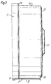
- a paper dispenser embodying the invention comprises a housing constituted by a circular backplate 1 and a domed cover 2 lockably mounted on the backplate, the housing containing support means in the form of an axially displaceable shaft assembly 3 for receiving thereon a roll 4 of toilet paper from which lengths of paper are to be dispensed to a user as required through an outlet opening 5 in the cover.
- the paper roll 4 is non-rotatably held on the shaft assembly 3 which itself is normally prevented from rotating by the inter-engagement of complementary stop means 6 on the shaft assembly 3 and the cover 2.
- the shaft assembly is axially displaced to free it for rotation by an actuating knob 7 by the user pressing on the knob 7, the shaft assembly being automatically returned to its non-rotatable position by biasing means 8 upon the user releasing the knob 7.
- a locking member 9 secures the knob 7, and thus the cover 2, to the backplate 1 to prevent unauthorised access to the interior of the housing, whilst permitting the necessary limited axial movement of the knob 7 to free the shaft assembly 3 for rotation.
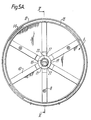
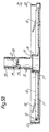
- the backplate 1 is shown in Figures 5A and 5B, from which it can be seen that the backplate is formed with radially extending strengthening ribs 10 deformed out of the general plane of the backplate.
- Three equiangularly spaced countersunk fixing holes 11 extend through respective ribs for the passage of fasteners, such as screws, by which the backplate 1 may be secured to a convenient vertical surface, such as a wall.
- the backplate 1 is formed with a mounting channel for the cover 2, such channel having an outer higher side wall 12 and a lower inner side wall 13. At four equally spaced locations therearound the inner surface of the outer side wall 12 is provided with a short screw thread 14.
- the backplate 1 is formed with a projecting hollow tapered spigot 15 which serves to support the shaft assembly 1 of the dispenser and to which the actuating knob 7 is locked in the assembled dispenser.
- the spigot 15 has a root portion 16 surrounded by an annular well 17 in the backplate 1 and a reduced diameter stem portion 18 forming a shoulder 19 at its junction with the root portion 16.
- the stem portion 18 presents four longitudinal locating ribs 20.
- the stem portion 18 has a transversely extending wall 21 formed with a locking slot 22.
- a locking abutment 23 extending perpendicularly to the length of the slot 22 is provided substantially midway along the slot on the surface of the wall 21 nearest the root portion 16.
- the domed cover 2 has a slightly conical side wall 24 and a circular slightly domed end wall 25 provided with a central circular aperture 26 surrounded by a raised lip 27. Adjacent the aperture 26 an annular rim is formed with a ring of teeth 38 facing the backplate 1 and constituting part of the stop means 6. Near the open end of the side wall 24 the external surface of the wall is formed at four equally spaced locations with an inclined thread 28 of the same circumferential extent as that of the thread 14 on the backplate.
- the side wall 24 is formed with a thread 29 extending parallel to the backplate and of the same extent as the thread 28, the threads 28 and 29 converging at one end so that the spacing between the ends of the threads is less than the width of the threads axially of the wall 24.
- radially extending pips may be provided on the surface of wall 13 within the mounting channel and on the inner surface of side wall 24 and arranged to pass one another during the clockwise rotation of cover 2 just before full engagement of the threads on the backplate and cover, so as to prevent inadvertent unscrewing of the cover.
- An outwardly extending trim flange 59 on the outsie surface of the cover side wall 24 hides the joint between the cover and backplate 1 to improve the appearance of the dispenser.
- the outlet opening 5 is formed mainly in the cover side wall 24 but, in order to reduce the necessary axial length of the cover, also extends a small way into the backplate 1, requiring the channel walls 12 and 13 to be cut away over part of their angular extent.
- the opening 5 has a pair of serrated edges 30 to assist in severing lengths from the paper roll 4.
- Figure 2 shows that the shaft assembly of the dispenser comprises a first sleeve 31 and a second sleeve 32, the first sleeve having a larger diameter portion 33 guided on the root portion of the spigot 15 and a smaller diameter portion 34 guided on the stem portion 18 of the spigot, the sleeve portions 33 and 34 being connnected by a radially extending shoulder 35.
- the larger diameter first sleeve portion 33 presents at its free end a clamping flange 40 and adjacent thereto four axial triangular gripping ribs 41 for securely holding the paper roll 4 on the shaft assembly.
- the smaller diameter first sleeve portion 34 has an end wall 36 at its free end and is externally screwthreaded at such free end.
- the second sleeve 32 has a cylindrical body 37 which is internally screwthreaded at one end for screwing into the smaller diameter first sleeve portion 34.
- the other end of the second sleeve 32 terminates in a centrally apertured circular end plate 39 defining a second clamping flange 40' with adjacent gripping ribs 41' on the second sleeve 32.
- the end plate 39 At its outer periphery the end plate 39 has a ring of teeth 42 constituting part of the stop means 6 and co-operating with the teeth 38 on the cover 2.
- the inner periphery of the end plate 39 has an axially extending hub 43.
- the sleeves 31 and 32 are pressed to the right in Figure 2 by biasing means 8 in the form of a compression spring 50 which is received on the spigot stem 18 and acts between the spigot shoulder 19 and the shoulder 35 of sleeve 31, thereby pressing the teeth 42 into engagement with the teeth 38.
- biasing means 8 in the form of a compression spring 50 which is received on the spigot stem 18 and acts between the spigot shoulder 19 and the shoulder 35 of sleeve 31, thereby pressing the teeth 42 into engagement with the teeth 38.
- the first and second sleeves 31 and 32 are shown in more detail in Figures 6A and 6B and Figures 7A to 7C, where it can be seen that a central hexagonally shaped orifice 44 is formed in the hub 43 of the end wall 36 of sleeve 31 and a similar central hexagonal orifice 45 is formed in the end plate 39 of the sleeve 32.
- the two orifices 44 and 45 are aligned to receive a hexagonal cross-section shank 46 ( Figure 2) of the actuating knob 7 of the dispenser, so that the shaft assembly 3 and knob 7 are coupled togther for rotation, although independently movable in the axial direction.
- End plate 39 is, as shown in Figure 78, provided with three strengthening ribs 47.
- the actuating knob 7 has a central axial bore 48 which extends through the shank 46 and is closed by an end wall 49 of the shank.
- a slot 51 is provided in the wall 49 to permit the passage of a locking part of the locking member 9, whilst a head 52 of the member remains slidable within the bore 48.
- a transverse locking bar 53 of the member 9 can pass through the locking slot 22 in the internal spigot wall 21 in one orientation of the bar 53 and is then held captive by rotating the member 9 through 90!using the key 54 which is insertable into the bore 48 and has tines 55 adapted to be received in corresponding axial slots 56 ( Figure 8B) in the head 52 of the locking member 9.
- a retaining bar 57 perpendicular to the locking bar 53 and received between the walls 21 and 49 prevents unauthorised removal of the locking member 9, whilst permitting limited axial movement of the actuating knob 7.
- the key 54 and the various parts of the dispenser are made of appropriate strong plastics materials.
- the cover may be made of translucent and/or coloured plastics material.
- Installation of the described paper dispenser is accomplished by first attaching the backplate 1 to a suitable vertical surface in a toilet so that the putlet aperture will be positioned at the bottom.
- the paper roll is mounted on the shaft assembly 3 by unscrewing the sleeves 31 and 32, inserting each sleeve into a respective end of the roll 4, and then screwing the sleeves 31 and 32 together until the roll is firmly held between the clamping flanges 35 and 40 and the hexagonal orifices 44 and 45 are also aligned.
- the shaft assembly is then placed on the backplate spigot 15 with the interposition of bias spring 50 and the cover 2 is offered up over the roll.
- the free end of the side wall 24 of the cover is introduced into the peripheral channel of the backplate with the baseplate threads 14 and cover threads 28 and 29 offset and, with the end of the cover 2 pressed against the base of the backplate channel, the cover is rotated clockwise to bring the threads into their engaged condition.
- knob 7 with the locking member therein is inserted through the aligned hexagonal orifices of the sleeves 31 and 32.
- the key 54 is inserted to grip the head of the locking member 9 to. orient it so that is passes through the locking slot 22 and then to rotate the_ locking member through 90i into its captive position holding the actuating knob 7 to the spigot 15.
- a rim 58 on the knob 7 overlaps the toothed rim 38 of the cover end wall 25 to retain the cover against unauthorised removal in the locked condition.
- the shaft assembly 3 is normally biased to the right in Figure 2 by the spring 50 so that the teeth 38 and 42 engage and prevent rotation of the shaft and the roll 4 thereon.
- the actuating knob 7 In order to remove paper from the roll, the actuating knob 7 must first be depressed to press on the hub of sleeve 32 and displace the shaft assembly away from the cover and disengage the teeth 38 and 42.
- the well 17 in the baseplate allows the final part of the necessary displacement of the shaft assembly, while keeping the axial dimension of the dispenser to a minimum.
- paper may now be dispensed in a controlled fashion from the roll 4 through the outlet opening 5 by rotation of the knob 7 and torn off by means of the serrated edges 30.
- the spring 50 Upon release of the knob 7, the spring 50 returns the shaft assembly to its normal non-rotatable condition, thereby preventing paper being removed from the roll simple by pulling on the end of the paper through the outlet opening 5.
- the dished head of the knob 7 wiithin the rim 58 is so contoured that, should a user attempt simply to maintain the knob depressed with one hand whilst pulling the paper through the outlet opening 5 with the other hand, the user will find it extremely difficult to maintain the rotating knob depressed.
- replacement of an empty paper roll 4 is effected by first releasing the locking member 9 from the backplate spigot 15 using the key 54.
- the cover 2 may then be rotated anticlockwise to release it from the backplate and the second sleeve 32 of the shaft assembly unscrewed.
- the cardboard former of the empty paper roll may then be removed and a fresh paper roll introduced over the first sleeve 31.
- the second sleeve is then screwed back onto the first sleeve 31 and tightened, ensuring that the hexagonal orifices are aligned in the tightened condition.
- the cover may then be replaced, rotated to engage it with the backplate and finally re-locked by means of the key 54.
Landscapes
- Health & Medical Sciences (AREA)
- Public Health (AREA)
- Unwinding Webs (AREA)
Priority Applications (1)
| Application Number | Priority Date | Filing Date | Title |
|---|---|---|---|
| EP82304900A EP0103659A1 (de) | 1982-09-16 | 1982-09-16 | Papierspender |
Applications Claiming Priority (1)
| Application Number | Priority Date | Filing Date | Title |
|---|---|---|---|
| EP82304900A EP0103659A1 (de) | 1982-09-16 | 1982-09-16 | Papierspender |
Publications (1)
| Publication Number | Publication Date |
|---|---|
| EP0103659A1 true EP0103659A1 (de) | 1984-03-28 |
Family
ID=8189772
Family Applications (1)
| Application Number | Title | Priority Date | Filing Date |
|---|---|---|---|
| EP82304900A Withdrawn EP0103659A1 (de) | 1982-09-16 | 1982-09-16 | Papierspender |
Country Status (1)
| Country | Link |
|---|---|
| EP (1) | EP0103659A1 (de) |
Cited By (7)
| Publication number | Priority date | Publication date | Assignee | Title |
|---|---|---|---|---|
| EP0270383B1 (de) * | 1986-12-05 | 1991-06-12 | Dudley Industries Ltd. | Rollenausgeber |
| EP0457731A1 (de) * | 1990-05-16 | 1991-11-21 | Steiner Company International S.A. | Spender für Toilettenpapierrollen |
| AU632126B2 (en) * | 1989-05-29 | 1992-12-17 | Mark James Brunton | Paper roll holder |
| EP0698367A1 (de) * | 1994-08-16 | 1996-02-28 | James River Paper Company, Inc. | Spindeladaptervorrichtung für Papierrollen |
| GB2296006A (en) * | 1994-12-13 | 1996-06-19 | David Kennedy | Paper tissue dispenser |
| CN111344240A (zh) * | 2017-09-15 | 2020-06-26 | 梅莉塔英国有限公司 | 分配器 |
| CN111344243A (zh) * | 2017-09-15 | 2020-06-26 | 梅莉塔英国有限公司 | 分配器 |
Citations (2)
| Publication number | Priority date | Publication date | Assignee | Title |
|---|---|---|---|---|
| US4108513A (en) * | 1976-12-17 | 1978-08-22 | Cepasy Ag | Paper dispenser, especially toilet paper dispenser |
| US4223964A (en) * | 1979-03-19 | 1980-09-23 | Kilgore Bobby R | Tissue holder |
-
1982
- 1982-09-16 EP EP82304900A patent/EP0103659A1/de not_active Withdrawn
Patent Citations (2)
| Publication number | Priority date | Publication date | Assignee | Title |
|---|---|---|---|---|
| US4108513A (en) * | 1976-12-17 | 1978-08-22 | Cepasy Ag | Paper dispenser, especially toilet paper dispenser |
| US4223964A (en) * | 1979-03-19 | 1980-09-23 | Kilgore Bobby R | Tissue holder |
Cited By (12)
| Publication number | Priority date | Publication date | Assignee | Title |
|---|---|---|---|---|
| EP0270383B1 (de) * | 1986-12-05 | 1991-06-12 | Dudley Industries Ltd. | Rollenausgeber |
| AU632126B2 (en) * | 1989-05-29 | 1992-12-17 | Mark James Brunton | Paper roll holder |
| EP0457731A1 (de) * | 1990-05-16 | 1991-11-21 | Steiner Company International S.A. | Spender für Toilettenpapierrollen |
| CH683148A5 (fr) * | 1990-05-16 | 1994-01-31 | Steiner Co Int Sa | Distributeur de papier hygiénique en rouleau. |
| EP0698367A1 (de) * | 1994-08-16 | 1996-02-28 | James River Paper Company, Inc. | Spindeladaptervorrichtung für Papierrollen |
| GB2296006A (en) * | 1994-12-13 | 1996-06-19 | David Kennedy | Paper tissue dispenser |
| CN111344240A (zh) * | 2017-09-15 | 2020-06-26 | 梅莉塔英国有限公司 | 分配器 |
| CN111344243A (zh) * | 2017-09-15 | 2020-06-26 | 梅莉塔英国有限公司 | 分配器 |
| US11155436B2 (en) | 2017-09-15 | 2021-10-26 | Melitta Uk Ltd | Dispenser |
| US11155435B2 (en) | 2017-09-15 | 2021-10-26 | Melitta Uk Limited | Dispenser |
| CN111344243B (zh) * | 2017-09-15 | 2022-01-07 | 梅莉塔英国有限公司 | 分配器 |
| CN111344240B (zh) * | 2017-09-15 | 2022-02-01 | 梅莉塔英国有限公司 | 分配器 |
Similar Documents
| Publication | Publication Date | Title |
|---|---|---|
| US4108513A (en) | Paper dispenser, especially toilet paper dispenser | |
| US5833169A (en) | Large roll bathroom tissue dispenser with stub roll holder | |
| CA2148727C (en) | Paper towel dispenser for dispensing towelling from inside diameter of roll | |
| CA2101295C (en) | Adjustable nozzle for a dispenser | |
| US5857642A (en) | Paper towel dispenser | |
| US4088276A (en) | Tape holder and dispenser | |
| EP0091411B1 (de) | Papierrollenhalter mit zentraler Papierausgabe | |
| EP0473247B1 (de) | Papierhandtuchspender (mit Bremse) | |
| US5851347A (en) | Stamp affixer apparatus and method | |
| US5292046A (en) | Roll film dispenser | |
| AU646471B2 (en) | Variable orifice centerflow dispenser | |
| US4919350A (en) | Holder/dispenser for paper in roll form | |
| US5323980A (en) | Anti-theft distributors for roll materials | |
| US5366175A (en) | Apparatus for dispensing web material from a coreless roll having anti-theft device | |
| CA2024368A1 (en) | Sheet dispensers | |
| US4354643A (en) | Bathroom tissue holder | |
| US20020043538A1 (en) | Earplug dispenser | |
| EP0103659A1 (de) | Papierspender | |
| GB2104871A (en) | A paper dispenser | |
| US20210289994A1 (en) | Convertible Dispenser | |
| WO2004056250A1 (en) | Solid rolls dispenser | |
| US7124976B1 (en) | Apparatus for dispensing sheet material from a roll | |
| US5490625A (en) | Paper towel and toilet paper portable dispenser | |
| US5556054A (en) | Anti-theft distribution for roll materials | |
| US3910463A (en) | Closure for liquid container |
Legal Events
| Date | Code | Title | Description |
|---|---|---|---|
| PUAI | Public reference made under article 153(3) epc to a published international application that has entered the european phase |
Free format text: ORIGINAL CODE: 0009012 |
|
| AK | Designated contracting states |
Designated state(s): AT BE CH DE FR IT LI LU NL SE |
|
| STAA | Information on the status of an ep patent application or granted ep patent |
Free format text: STATUS: THE APPLICATION IS DEEMED TO BE WITHDRAWN |
|
| 18D | Application deemed to be withdrawn |
Effective date: 19841128 |
|
| RIN1 | Information on inventor provided before grant (corrected) |
Inventor name: STEVENS, GRAHAM D. |