EP0103662A1 - Systèmes de régulation pour machines de soudage électrique par points - Google Patents
Systèmes de régulation pour machines de soudage électrique par points Download PDFInfo
- Publication number
- EP0103662A1 EP0103662A1 EP82305683A EP82305683A EP0103662A1 EP 0103662 A1 EP0103662 A1 EP 0103662A1 EP 82305683 A EP82305683 A EP 82305683A EP 82305683 A EP82305683 A EP 82305683A EP 0103662 A1 EP0103662 A1 EP 0103662A1
- Authority
- EP
- European Patent Office
- Prior art keywords
- flip
- flop
- peak voltage
- weld
- peak
- Prior art date
- Legal status (The legal status is an assumption and is not a legal conclusion. Google has not performed a legal analysis and makes no representation as to the accuracy of the status listed.)
- Withdrawn
Links
- 238000003466 welding Methods 0.000 title claims abstract description 33
- 230000001960 triggered effect Effects 0.000 claims abstract description 9
- 230000000977 initiatory effect Effects 0.000 claims abstract description 7
- 238000000034 method Methods 0.000 claims description 5
- 238000001514 detection method Methods 0.000 claims description 4
- 238000010586 diagram Methods 0.000 description 4
- 230000003044 adaptive effect Effects 0.000 description 2
- 230000002159 abnormal effect Effects 0.000 description 1
- JEIPFZHSYJVQDO-UHFFFAOYSA-N iron(III) oxide Inorganic materials O=[Fe]O[Fe]=O JEIPFZHSYJVQDO-UHFFFAOYSA-N 0.000 description 1
- 238000004519 manufacturing process Methods 0.000 description 1
- 238000012544 monitoring process Methods 0.000 description 1
- 238000003908 quality control method Methods 0.000 description 1
- 230000000630 rising effect Effects 0.000 description 1
Images



Classifications
-
- B—PERFORMING OPERATIONS; TRANSPORTING
- B23—MACHINE TOOLS; METAL-WORKING NOT OTHERWISE PROVIDED FOR
- B23K—SOLDERING OR UNSOLDERING; WELDING; CLADDING OR PLATING BY SOLDERING OR WELDING; CUTTING BY APPLYING HEAT LOCALLY, e.g. FLAME CUTTING; WORKING BY LASER BEAM
- B23K11/00—Resistance welding; Severing by resistance heating
- B23K11/24—Electric supply or control circuits therefor
- B23K11/25—Monitoring devices
Definitions
- This invention relates to systems for the control of electric spot-welding machines.
- An automatic adaptive control system for spot-welding machines is known in which during a welding operation the peak voltage is detected and weld termination is initiated shortly after the peak in order to avoid weld splash.
- this system suffers from certain operational disadvantages.
- the time of occurrence of the peak voltage during a welding operation can vary according to the nature of the components being welded, and whereas an early peak voltage can be quite normal in some conditions, there are other circumstances in which an early peak may arise abnormally and thereby give a spurious indication of the state that the weld has reached.
- the characteristic curve in Figure 1 shows the normal circumstances in which the voltage settles to a low value, as at 14, before 'wake-up', then rises progressively through and beyond 'wake-up' and the front stop' 12 to peak at 15, after which weld termination occurs at 16 when the voltage has dropped below the peak value 15 by a pre-set amount. If the voltage peaks later than the front stop time, as shown, the weld will be satisfactory. The problem arises if the voltage peaks before the front stop time 12, in which case the weld will probably be unsatisfactory.
- a method of automatic control for an electric spot-welding machine canprising detecting the peak voltage across thenacnt during the welding cycle and employing the detected peak voltage to determine the point of automatic initiation of the termination of welding shortly thereafter, setting a front stop time during the welding cycle selected such that if there is any undesirably early peaking of the voltage that if Employed to determine the initiation of weld termination would not lead to a satisfactory weld such peaking will occur prior to the front stop time setting, and causing any such early peaking of the voltage prior to the front stop time setting to reset the peak detector without initiation of weld termination.
- the invention further provides electric spot-welding control apparatus comprising a peak detector for detecting the peak voltage across the weldment during each welding cycle, weld termination circuitry operative to terminate each weld automatically a calculated period after the occurrence of a peak voltage in response to detection of said peak voltage by the peak detector, means to select and set a front stop time during the welding cycle said front stop time being selected such that any undesirably early voltage peak that would result in an unsatisfactory weld if the weld termination circuitry were to respond to it will occur before the front stop time, and means to inhibit response by the weld termination circuitry to a peak voltage occurring before the selected front stop time and to reset the peak detector for detection of the next peak voltage.
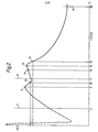
- the voltage characteristic of Figure 2 shows the simple situation in which the voltage is rising at wake-up 11 but peaks, as at 17, before the front stop 12, at a time in the weld cycle when it is known that a weld termination at the point 18, representing the preset voltage drop below the peak at which the system is set to terminate the welding cycle, would be too early to give a satisfactory weld. If it is reliably known that this single too early peak will occur, the system can be adapted to override it by arranging for the peak detector not to respond to the first peak and 'termination' incident but to be re- set for response, as at 19, as the voltage rises again beyond the front stop 12. Weld termination will then occur correctly at the point 16 after the second peak 15.
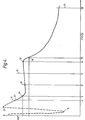
- the first 'termination' incident at 18 can be treated as a 'switch-on' point, a predetermined time period, say 3 time cycles, after which the peak detector is re-set. But this, of course, involves the operator knowing that two peaks will always occur and when the first peak will occur in relation to the front stop.
- Figure 3 is a circuit and block diagram of a simple cascade of flip-flops 21, 22, 23 for over-riding the first 'termination' incident and thereafter re-setting the peak detector.
- 'Termination' signals are applied to both the first and second flip-flops 21, 22 via a gate 32. If the over-ride switch 24 is closed the second flip-flop 22 is triggered directly. If the switch 24 is open, the first flip-flop 21 has to be triggered by the first 'termination' incident before the second flip-flop can be triggered by the second termination signal.
- the third flip-flop 23 is triggered directly by the first flip-flop 21 and applies the peak detector re-set signal to the base of a peak detector transistor.
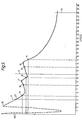
- Figure 5 shows a third type of voltage characteristic which is essentially a combination of the characteristic curves of Figures 2 and 4. That is to say, there is a very early voltage spike 25 producing a first 'termination' incident 26, and the further voltage peak 17 occurring before the front stop 12, producing a second 'termination' incident 18, and both incidents 26 and 18 must be discriminated against. This can be achieved if any 'termination' incident occurring during a pre-set time period after 'wake-up' cannot trigger termination of the welding cycle but only serves to re-set the peak level detector. Thus, the 'termination' incident 26 causes the peak level detector to re-set for the first time at 28, and the second 'termination' incident 18 causes the peak level detector to re-set a second time at 19. However, beyond the front stop 12 the single termination event 16 suffices to trigger termination of the welding cycle.
- Figure 6 shows a circuit for achieving this last result to deal with the situation of Figure 5.
- a counter 29 is incorporated to which the 'wake-up' signal is applied via gate 33, and the first flip-flop 30 is not triggered until the pre-set time in the counter runs out.
- 'Termination' signals are applied to the second flip-flop 31 via the gate 32 but are ineffective to clock the flip-flop until the trigger signal arrives from the first flip-flop 30.
- the peak detector re-set signals are applied to the peak detector from the output 34 of flip-flop 31.
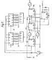
- FIG. 7 a circuit such as that of Figure 7 may be employed.
- the circuit of Figure 7 is basically that of Figure 6 with two flip-flops 31A, 31B in cascade instead of the one flip-flop 31.
- the extra flip-flop which also receives the 'termination' signal via gate 32, ensures that a second 'termination' incident occurring while the time set by the counter 29 is still running will produce termination of the welding cycle even though the first flip-flop 30 has still not been clocked by the counter. After the set time has expired and the counter has clocked the flip-flop 30, a single 'termination' incident will suffice to terminate the welding cycle.
- Flip-flop 31A provides peak detector re-set.
- the counters are driven by square wave clock pulses generated within the main control system so that all operations are in synchronism.
Landscapes
- Engineering & Computer Science (AREA)
- Mechanical Engineering (AREA)
- Arc Welding Control (AREA)
- Resistance Welding (AREA)
Applications Claiming Priority (2)
| Application Number | Priority Date | Filing Date | Title |
|---|---|---|---|
| GB8226418 | 1982-09-16 | ||
| GB8226418 | 1982-09-16 |
Publications (1)
| Publication Number | Publication Date |
|---|---|
| EP0103662A1 true EP0103662A1 (fr) | 1984-03-28 |
Family
ID=10532948
Family Applications (1)
| Application Number | Title | Priority Date | Filing Date |
|---|---|---|---|
| EP82305683A Withdrawn EP0103662A1 (fr) | 1982-09-16 | 1982-10-26 | Systèmes de régulation pour machines de soudage électrique par points |
Country Status (2)
| Country | Link |
|---|---|
| EP (1) | EP0103662A1 (fr) |
| JP (1) | JPS5950980A (fr) |
Citations (4)
| Publication number | Priority date | Publication date | Assignee | Title |
|---|---|---|---|---|
| US3493715A (en) * | 1966-05-09 | 1970-02-03 | Taylor Winfield Corp | Transistorized sequence timer for resistance welding machines |
| GB2081925A (en) * | 1980-08-08 | 1982-02-24 | Nishikawa Masahiro | Resistance welding control |
| EP0050950A2 (fr) * | 1980-10-16 | 1982-05-05 | Square D Company | Unité de contrôle à réaction pour souder |
| DE3150199A1 (de) * | 1980-12-19 | 1982-07-01 | Midland-Ross Corp., 44122 Cleveland, Ohio | "verfahren und anordnung zur automatischen steuerung von widerstandsschweissvorrichtungen" |
-
1982
- 1982-10-26 EP EP82305683A patent/EP0103662A1/fr not_active Withdrawn
- 1982-11-29 JP JP21054282A patent/JPS5950980A/ja active Pending
Patent Citations (4)
| Publication number | Priority date | Publication date | Assignee | Title |
|---|---|---|---|---|
| US3493715A (en) * | 1966-05-09 | 1970-02-03 | Taylor Winfield Corp | Transistorized sequence timer for resistance welding machines |
| GB2081925A (en) * | 1980-08-08 | 1982-02-24 | Nishikawa Masahiro | Resistance welding control |
| EP0050950A2 (fr) * | 1980-10-16 | 1982-05-05 | Square D Company | Unité de contrôle à réaction pour souder |
| DE3150199A1 (de) * | 1980-12-19 | 1982-07-01 | Midland-Ross Corp., 44122 Cleveland, Ohio | "verfahren und anordnung zur automatischen steuerung von widerstandsschweissvorrichtungen" |
Also Published As
| Publication number | Publication date |
|---|---|
| JPS5950980A (ja) | 1984-03-24 |
Similar Documents
| Publication | Publication Date | Title |
|---|---|---|
| CA1095174A (fr) | Circuit de controle et de relance d'un ordinateur numerique | |
| JP2959466B2 (ja) | アークスタッド式溶接方法 | |
| US4571696A (en) | Electronically controlled screwdriver with quality check indicator | |
| US4279143A (en) | Electronic pinking detector | |
| US4009361A (en) | Electrical discharge machining apparatus with monitoring circuit and means to check the operability of the monitoring circuit | |
| US4027102A (en) | Voice versus pulsed tone signal discrimination circuit | |
| US4644334A (en) | Monitoring apparatus for a construction machine | |
| US3551672A (en) | Method and apparatus for measuring rates of random pulses and alarm actuated thereby | |
| US3433921A (en) | Apparatus and method for indicating defective welds | |
| US4443687A (en) | Method and system for automatically terminating a MIG welding operation | |
| US3627967A (en) | Power switch short circuit detector for edm | |
| EP0247059A1 (fr) | Appareil et procede de protection d'un circuit electrique. | |
| CH663371A5 (de) | Stromquelle fuer funkenerosionsbearbeitung mit einer drahtelektrode. | |
| FR2571500A1 (fr) | Ensemble electronique de detection des variations fugitives d'une tension electrique en fonction du temps | |
| US5514851A (en) | Prevention of contact tube melting in arc welding | |
| EP0051929B1 (fr) | Unité de contrôle à réaction pour souder | |
| JPH06262493A (ja) | Aeによる工具寿命判定の方法と、その方法を実施する装置並びにその方法と装置を利用した自動工具交換システム | |
| US4090961A (en) | Process and apparatus for monitoring the electrical discharge efficiency of an EDM machine | |
| JPS5821173A (ja) | 電源系統の異常検出判別装置 | |
| US5128507A (en) | Weld control structure for and method of delaying initiation of a weld | |
| JPH08197335A (ja) | ワイヤ放電加工機における断線検出方法 | |
| JP3227671B2 (ja) | エンジン溶接機の遠隔起動システム | |
| US3597661A (en) | Monitoring and shutdown apparatus | |
| US5486765A (en) | Insulating condition detecting apparatus for a wire-cut electrical discharge machine | |
| US5393947A (en) | Method and device for controlling a wire cut electric discharging machine |
Legal Events
| Date | Code | Title | Description |
|---|---|---|---|
| PUAI | Public reference made under article 153(3) epc to a published international application that has entered the european phase |
Free format text: ORIGINAL CODE: 0009012 |
|
| AK | Designated contracting states |
Designated state(s): DE FR GB |
|
| STAA | Information on the status of an ep patent application or granted ep patent |
Free format text: STATUS: THE APPLICATION IS DEEMED TO BE WITHDRAWN |
|
| 18D | Application deemed to be withdrawn |
Effective date: 19850429 |
|
| RIN1 | Information on inventor provided before grant (corrected) |
Inventor name: SUGIMOTO, NOBUO Inventor name: DENNING, ROBERT EDWIN ARTHUR |