EP0103664A1 - Dispositif d'injection par aspiration sur la peau - Google Patents
Dispositif d'injection par aspiration sur la peau Download PDFInfo
- Publication number
- EP0103664A1 EP0103664A1 EP82730113A EP82730113A EP0103664A1 EP 0103664 A1 EP0103664 A1 EP 0103664A1 EP 82730113 A EP82730113 A EP 82730113A EP 82730113 A EP82730113 A EP 82730113A EP 0103664 A1 EP0103664 A1 EP 0103664A1
- Authority
- EP
- European Patent Office
- Prior art keywords
- chamber
- cannula
- skin
- sleeve
- suction cup
- Prior art date
- Legal status (The legal status is an assumption and is not a legal conclusion. Google has not performed a legal analysis and makes no representation as to the accuracy of the status listed.)
- Granted
Links
Images


Classifications
-
- A—HUMAN NECESSITIES
- A61—MEDICAL OR VETERINARY SCIENCE; HYGIENE
- A61M—DEVICES FOR INTRODUCING MEDIA INTO, OR ONTO, THE BODY; DEVICES FOR TRANSDUCING BODY MEDIA OR FOR TAKING MEDIA FROM THE BODY; DEVICES FOR PRODUCING OR ENDING SLEEP OR STUPOR
- A61M5/00—Devices for bringing media into the body in a subcutaneous, intra-vascular or intramuscular way; Accessories therefor, e.g. filling or cleaning devices, arm rests
- A61M5/42—Devices for bringing media into the body in a subcutaneous, intra-vascular or intramuscular way; Accessories therefor, e.g. filling or cleaning devices, arm rests having means for desensitising skin, for protruding skin to facilitate piercing, or for locating point where body is to be pierced
- A61M5/425—Protruding skin to facilitate piercing, e.g. vacuum cylinders, vein immobilising means
Definitions
- the invention relates to the field of medical technology, especially to the field of injection technology.
- suction injection In a type of "suction injection", the skin is lifted into a cannula standing inside a suction cup, in particular for the supply of liquid medication under the skin, by means of negative pressure.
- Suction injection devices avoid the risk of accidental injection into the bloodstream and touching bones and nerves. So far, they have apparently only been used occasionally in veterinary medicine to counteract evasive movements by fixing the cannula. The automation of the functional sequences seems indispensable for use in humans, in particular for self-injection of the diabetic.
- GNHein (2,743,723, discloseSt.v.Amerika, 1.5.1956), who had the negative pressure created by a rubber ball, recognized the difficulty of the cannula penetrating the skin too early due to different body surface curvature and skin elasticity, and solved the problem with an additional one the cannula reaching down to the skin.
- the invention seeks to remedy this.
- the invention as characterized in the claims, solves the problem of creating a device for subcutaneous injection in that there is no longer a partition between the skin and the cannula. It is a device for injection under negative pressure on the skin mainly for the administration of medication into the subcutaneous tissue, consisting of a chamber in which there is an air dilution generated during the manufacturing process, which is provided with a lid with a central funnel for the airtight fastening of a container with means is provided for dispensing a measured amount of liquid; a cannula shaft attached to that funnel and continuing its bore, the lower end of the cannula shaft extending with its tip into a suction cup, characterized in that the suction cup directly adjoins the vacuum-storing chamber and has a part in common with the bottom plate thereof, whereby a valve mechanism is present to prevent air pressure equalization between the suction cup and the chamber until the suction cup is in pressure contact with the skin.
- the injection is carried out by a syringe in the usual way or by a special metering pump, which can preferably be connected to a medication pressure bottle, solutions such as those described in published documents 25 51 991 (July 29, 1966 in Kunststoff) and 25 51 992 (August 5, 766) in Kunststoff) are constantly being improved.
- the advantages achieved by the invention are essentially to be seen in a reduction in the cost of manufacture and in a higher level of functional reliability.
- An already factory-welded cannula shaft or a cannula with its attachment for attaching a syringe already firmly connected to the device during production simplifies handling, especially for anxious and awkward patients, since the pot of the device can be handled better and the tool, which injures the cannula is not visible. Taking the injection accessories for use on the go is made easier by eliminating a special auxiliary tool for inserting a cannula.
- a prerequisite is a certain amount of friction between the syringe plunger and the cylinder, in order to empty it prematurely.
- a plunger lock such as a clamp just above the syringe barrel on the syringe plunger. This clamp must then either be removed again before the injection or it slides resiliently during the lowering of the syringe plunger by finger pressure on the same. With glass syringes, such clamps are often already installed in the cylinder cover.
- an auxiliary device which, after removing an adhesive film over the central conical funnel, allows the syringe to be fastened in the in the lid, without visually inspecting the device in the state of the cannula seal by skin suction; otherwise one would sacrifice a main advantage of the suction injection, namely to be able to select almost any skin area for injection and to protect the skin by changing the injection site. If there are no wound scars, even the injection over the carotid artery is completely harmless.
- An adhesive film can characteristically also be such that it continues over an opening in the lid of the so-called storage chamber, so that further pull on a freely hanging tab of the adhesive film by exposing that opening, penetration of the outside air and thus re-ventilation also in the
- the suction cup area causes the skin to withdraw from the cannula and the device can be removed with the syringe to remove the adhesion to the skin.
- the task of preventing premature penetration of the cannula tip into the skin prior to the vacuum action is achieved according to the invention in one example in that the cannula is surrounded by a sleeve which projects above the plane of the suction cup rim and which is upward within an internal cylinder of the chamber is displaceable.
- This sleeve expediently serves to open a valve mechanism between the chamber and the inner cylinder in order to initiate air pressure compensation towards the suction bell.
- the mechanism can be openings, which are brought into line with one another by this displacement of the parts.
- the sleeve carries a base ring, of which at least one arm extends with its end after a predetermined breaking point in the base plate of the Xammer, in order to open this predetermined breaking point when the sleeve is raised by the skin pressure.
- a valve opening in the base plate is covered by a film ring with airtight bonding of an annular zone around the valve opening, the film continuing upwards in a hat-like manner in a gap between the inner cylinder and the sleeve, at least around the upper end of the sleeve partially to span or attached to it be. If the sleeve is raised, the film edge is pulled away from the valve opening in the base plate and the air pressure equalization is initiated.
- a tear thread lies within the film sealing the valve opening, which extends to the upper end of the sleeve and, when raised, causes the sealing film to be pulled away or torn.
- a pipe socket is arranged eccentrically next to the cannula shaft in the chamber, which is open through the base plate into the suction bell and is filled by a valve pin, which is approximately at the level of the suction bell wheel ends down. This valve pin is designed so that it initially seals the pipe socket against the suction bell, but after lifting it releases the air flow into the chamber.
- the inner cylinder can be omitted and the cannula can extend through the entire chamber into the suction cup.
- the cannula attachment piece - unless a funnel of the same function as part of the lid is connected to a cannula shaft - is tightly welded to the lid of the chamber;
- the cannula shaft is expediently welded or fastened within the base plate, expediently within a very short pipe socket.
- the valve pin advantageously has an annular edge strip just below the upper end of the pipe socket and a further lower one, possibly with longitudinal openings for the passage of air. A wax or seal layer between the valve pin and pipe socket ensures permanent air exclusion.
- a kind of inner cylinder is again provided, but now as a depression from above. to bring a syringe barrel closer to the injection point while shortening the cannula shaft.
- This increases the dosing accuracy and reduces the loss of medication, which results from the residual amount remaining within the cannula shaft.
- the pipe socket and thus the valve pin are removed from the cannula.
- a ring extends from the valve pin to the center, which surrounds the cannula.
- the valve pin ends upwards: into a kind of cannula that breaks through a stopper membrane in the pipe socket to equalize the air pressure.
- a pipe connection, sealed against the so-called storage chamber, between the cover and base plate, which connects the suction bell to the outside air, can be used both for re-ventilation via ventilation of a cover film and for checking whether the valve mechanism was opened after sealing contact with the skin, at the right time for injection to choose.
- the sachet shown, which should contract under the influence of suction, is used for the demonstration according to the invention.
- a membrane cover over a lid opening or a membrane-like thinning of the lid of the chamber, with the aid of its retraction under the influence of vacuum, serves to check whether the device is still in a functional condition.
- less gas-permeable batches of polystyrene for the device can be selected as the production material, for a sleeve with a base plate and an arm serving as a valve pin, for example, polyvinyl chloride.
- the pipe socket is sealed with the valve pin, for example, under ultrasound or by diathermy or via the action of heat when the dec is welded on on the chamber inside a vacuum chamber.
- a device with a pipe socket as part of the valve mechanism can also first be provided with a cover, after which the valve pin is sealed in the vacuum chamber within the pipe socket.
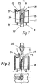
- a device is shown - described in more detail - as it looks when it has just been removed from the packaging. It consists of an outer cylinder (11) with a central funnel (79), which continues downwards into a fixed cannula shaft. An inner cylinder (76), which continues down into the suction bell (4), encloses the larger part of the cannula shaft. A sleeve (75) is slidable within the inner cylinder and projects beyond the suction cup rim at the bottom. A slit-shaped side opening (95) lies below the side opening (94) of the inner cylinder. An adhesive mass seals the space between this side opening (94) and the wall of the sleeve (75).
- the ring membrane (83) is drawn into the interior of the outer chamber by the negative air pressure and is covered by an adhesive film ... so that it seals a hole (97) in the ring membrane (83) and the funnel (79) with its adhesive underside Foil has a free one End (98).
- FIG. 2 shows an exemplary embodiment like that in FIG. 1, in which a half-channel holding a syringe with its clamp (99) is fastened on a jacket sleeve surrounding the injection device in such a way that the ready-to-use syringe with its attachment cone closes directly over the funnel opening (79) comes to lie.
- the state shown, in which - represented by a dashed line - the skin is drawn into the suction cup and has penetrated the tip of the cannula is a result of the following handling.
- the device was pressed against the skin with the suction cup rim, lifting the sleeve within the inner cylinder and covering the openings of the valve mechanism.
- the adhesive film (96) does not extend over the funnel.
- a syringe with its attachment cone is fastened tightly in the funnel of the lid of the device before the valve mechanism is triggered in order to equalize the air pressure.
- the device can also be connected to the neck of a metering device, as described in laid-open document 25 51 991 (dated July 29, 1966 in Kunststoff) and has since been further improved.
- a partial top view is shown directly below the longitudinal section of FIG.
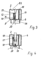
- Figure 3 shows a longitudinal section of the preferred embodiment, in which a cannula with its connector between the cannula shaft (28) and syringe is welded tightly in the center of a fixed lid (2).
- the chamber for the vacuum storage shows as a partition a base plate (9) which is penetrated by the end of the cannula shaft when the latter is sealed within the base plate.
- a pipe socket (10) in the base plate which protrudes into the chamber and serves as a receptacle for a valve pin (20).
- the valve pin touches the inner wall in the upper end of the pipe socket with an upper annular edge strip (12), the edge strip being sealed off from the inner wall of the pipe socket by a wax layer (13); a lower annular edge strip (14) of the valve pin with longitudinal interruptions for the passage of air lies near the lower end of the pipe socket and promotes the position stabilization of the valve pin, which ends at the level of the suction bell edge.
- a fine tube (15) which is closed before use using syringes by a sealing plaster (16), the removal of which after Injection can serve the re-ventilation of the suction cup.
- a thin spot in the cover (2) or an opening there, which is closed by the membrane (83) indicates from the fact that it is drawn into the chamber space that there is negative pressure, which is a prerequisite for the usability of the device.
- the skin pent up within the edge of the suction cup pushes the valve pin upwards, the wax seal breaks and the upper edge strip of the valve pin leaves the pipe socket, so that air from the suction cup penetrates into the chamber.
- the skin is lifted into the cannula and the injection can be carried out as described above.
- FIG 4 shows in longitudinal section a variation to the execution Example of Figure 4, in which the pipe socket (10) is closed at the top by a sealing plug (17) made of rubber.
- the valve pin (20) carries a cannula (18) which is open towards the side at its upper end and is corresponding to one by a flattening. projecting ledge in the pipe socket secured against rotation. At its lower end it bears the central ring (19).
- the valve pin In the illustrated stage of a skin drawn up from the chamber under the influence of a vacuum - represented by dashed lines - the valve pin has already been raised by the pressure of the skin on the ring (19).
- the cannula (18) of the valve pin has broken through the thinned center of the sealing plug and equalized the pressure between the chamber and the suction cup.
- Figure 5 illustrates in longitudinal section a modification of the device, as shown in Figures 1 and 2.
- the inner cylinder (76) has a central funnel (79) at the top in order to receive the connecting piece between the shaft and the metering medicament container of a cannula - which is not shown here.
- the edge (24) of the suction cup (4) is particularly offset from the outer cylinder (11) surrounding the suction cup.
- the base plate as the boundary between the suction cup and chamber has a wall thinner (84), which continues in a niche-like manner in the side wall of the suction cup and into which three resiliently outwardly bent arms (77) are engaged, which are connected by the base ring (22) to the sleeve ( 75) going out.
- the three arms are also shown in Figures 6 and 7 and evenly distributed over the circumference. If pressure is exerted on the base ring (22), the pointed ends (78) of the arms (77) can easily break through the wall thinner (84). The wall thinning can also be replaced by foils which close corresponding window openings in the base plate. In the evacuated state, the chamber is closed by the ring membrane (83).
- Figure 6 shows a schematic plan view of the ends of the arms (77) in their locking position.
- FIG. 7 shows an axial section with a partial side view of a device as in FIG. 5, but in connection with an attached cannula (28), which in turn is connected to a syringe. It can be seen how the end of an arm broke through the thinning of the base plate and the skin - shown in dashed lines - was lifted into the tip of the cannula after the air of the inner cylinder, which forms an inner chamber (26), partially flows out to the outer chamber (25) as a result of the pressure drop could.
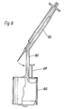
- FIG. 8 shows an auxiliary device for inserting a cannula into the device according to FIGS. 5 to 10.
- the auxiliary device consists of a cylindrical pot (80) which is open at the bottom and was placed over an injection device.
- the half-channel for guiding the syringe has a vertical part (81) and ends in an inclined (82).
- the usually filled and cannulated syringe is first inserted into the upper oblique part of the half-channel and tilted into the vertical during a downward movement, which allows the cannula to be inserted into the funnel of the injection device without endangering sterility by touch.
- the lowering of the mandrel (87) causes the membrane to be destroyed.
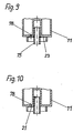
- FIG. 9 shows in longitudinal section the lower part of a device corresponding to that shown in FIGS. 1 and 2 with the cannula omitted.
- the valve mechanism between the chamber and the suction bell has been modified.
- the so-called storage chamber has the opening (78) towards the suction bell, which is closed by the annular edge of a hat-shaped membrane (23) sealed around the opening by adhesive.
- the hat-shaped membrane continues beyond the upper end of the sleeve (75), which projects below the edge of the suction cup.
- the center of the membrane (23) lying above the sleeve end either leaves space for the cannula to pass through or is pierced by it.
- FIG. 10 gives a representation corresponding to FIG. 9, but there is only an adhesive membrane over the opening (78).
- This membrane contains a tear thread (21) welded in, the knotted end of which is fastened in a slot at the upper end of the sleeve. If the sleeve is raised, pulling on the tear thread will remove the membrane over the valve opening and thus equalize the air pressure.
- FIG. 11 schematically shows in longitudinal section and on a 2: 1 scale an apparatus like that in FIG. 1 is enlarged.
- a hole (3) is guided vertically into the inner cylinder from the slope of the funnel.
- the funnel is closed by the attachment cone of a syringe, no air can escape if there is close skin contact after opening the valve mechanism. If the attachment cone of the syringe is withdrawn after the injection, it will find its way through the bore (3). a re-ventilation of the suction cup instead.
- An additional channel (6) can be useful when used in conjunction with an automatic injector.
- a hole (8) in the outer wall of the chamber can also be closed by an adhesive tape, the removal of which initiates the re-ventilation.
- the sack (27) of a sack cannula, which is inserted into the channel (6) in a sealed manner, has to be pushed a little to the side from the attachment cone of the syringe, as the situation shows; it collapses as soon as the valve mechanism has been operated as intended.
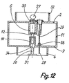
- FIG. 12 shows a modification of the exemplary embodiment of FIG. 3 in a longitudinal section when enlarged on a scale of 2: 1, the pipe socket and the cannula being additionally pulled apart somewhat for a clearer illustration.
- the pipe socket (10) which is closed in its upper end by the lower end of the piston-like edge strip (12) of the valve pin (20), the lower end of which Pressure plate (3l) carries.
- the piston-like edge strip continues upwards and bridges a free gap space in the chamber into the lower end of the pipe sleeve, which surrounds the channel (6), and seals it.
- the channel (6) in the bulge (29) widens immediately above the end of the valve pin.
- the sealing of the plug plate (30) with a bore which ends in a rubber bag (27) forms the end of the channel at the top.
- the connector of a cannula is sealed in the lid (2) immediately next to its protuberance for the channel (6).
- the cannula shaft is tightly welded in the base plate (9) within the short pipe sleeve (33), the cannula tip protruding into the suction cup (4).
- the cover (2) also carries an edge grommet (32) into which the cylinder of another suction cup can be inserted for better stacking of different devices on top of one another.
- a filled hypodermic syringe is sealingly inserted into the connector of the cannula.
- the suction cup is pulled off the edge of the device underneath under tension on the chamber.
- a sterile packaging sleeve (not shown) had previously been removed.
- the edge of the suction cup (4) is pressed against the skin, which, due to its elasticity, accumulates under the pressure plate (31) of the valve pin (20) until the valve connection between the piston-like edge strip (12) and the pipe socket (10 ) and the pipe sleeve of the channel (6) is blown up and, as a result of air pressure compensation, both the skin is lifted into the cannula and the rubber bag (27) is contracted.
- the reduction of the surface in contact with the wall by doubling the piston-like edge strip when adding a ring strip (33) which supports the guidance of the valve pin in the lower part of the pipe socket (10) also reduces the frictional resistances.
- inventive elements described can also be used, combined and varied in other injectors without ceasing to be part of this invention.
- an outgoing from a sleeve can be angled upwards
- the single arm ends as a valve pin in a pipe socket inside the chamber.
- the chamber can have square or polygonal wall boundaries to increase grip, prevent rolling away and reduce the packaging dead space.
- Such deviations which could only be incompletely enumerated in the examples, are still within the scope of the invention.
- the suction cup itself can also deviate from the circular shape, as tests have shown.
Landscapes
- Health & Medical Sciences (AREA)
- Vascular Medicine (AREA)
- Life Sciences & Earth Sciences (AREA)
- Animal Behavior & Ethology (AREA)
- Anesthesiology (AREA)
- Biomedical Technology (AREA)
- Heart & Thoracic Surgery (AREA)
- Hematology (AREA)
- Dermatology (AREA)
- Engineering & Computer Science (AREA)
- General Health & Medical Sciences (AREA)
- Public Health (AREA)
- Veterinary Medicine (AREA)
- Infusion, Injection, And Reservoir Apparatuses (AREA)
- Massaging Devices (AREA)
- Insulators (AREA)
Priority Applications (3)
| Application Number | Priority Date | Filing Date | Title |
|---|---|---|---|
| EP82730113A EP0103664B1 (fr) | 1982-08-25 | 1982-08-25 | Dispositif d'injection par aspiration sur la peau |
| DE8282730113T DE3274802D1 (en) | 1982-08-25 | 1982-08-25 | Device for injection by the effect of vacuum on the skin |
| AT82730113T ATE24404T1 (de) | 1982-08-25 | 1982-08-25 | Vorrichtung fuer die einspritzung unter unterdruckwirkung auf die haut. |
Applications Claiming Priority (1)
| Application Number | Priority Date | Filing Date | Title |
|---|---|---|---|
| EP82730113A EP0103664B1 (fr) | 1982-08-25 | 1982-08-25 | Dispositif d'injection par aspiration sur la peau |
Publications (2)
| Publication Number | Publication Date |
|---|---|
| EP0103664A1 true EP0103664A1 (fr) | 1984-03-28 |
| EP0103664B1 EP0103664B1 (fr) | 1986-12-30 |
Family
ID=8190040
Family Applications (1)
| Application Number | Title | Priority Date | Filing Date |
|---|---|---|---|
| EP82730113A Expired EP0103664B1 (fr) | 1982-08-25 | 1982-08-25 | Dispositif d'injection par aspiration sur la peau |
Country Status (3)
| Country | Link |
|---|---|
| EP (1) | EP0103664B1 (fr) |
| AT (1) | ATE24404T1 (fr) |
| DE (1) | DE3274802D1 (fr) |
Cited By (19)
| Publication number | Priority date | Publication date | Assignee | Title |
|---|---|---|---|---|
| DE3708031A1 (de) * | 1986-03-20 | 1987-11-12 | Wolfgang Dr Med Wagner | Messeinrichtung oder induktionseinrichtung mit messeinrichtung oder vorrichtung zur materialgewinnung fuer eine messvorrichtung fuer stoffwechselzustaende im blut mittels punktion unter anwendung von unterdruck innerhalb einer saugglocke bei verlagerung der messzone ausserhalb des spitzenbereiches des punktionsgeraetes |
| DE3730469A1 (de) * | 1986-09-08 | 1988-06-16 | Wolfgang Dr Med Wagner | Einrichtung zur saugdiagnostik oder sauginjektion |
| EP0671146A4 (fr) * | 1993-08-10 | 1995-12-06 | Advance Kk | Instrument simple de prelevement du sang. |
| EP0797951A4 (fr) * | 1995-05-25 | 1999-11-17 | Advance Kk | Dispositif de prelevement de sang |
| EP1476210A4 (fr) * | 2002-02-11 | 2005-05-25 | Antares Pharma Inc | Injecteur intradermique |
| US7740651B2 (en) | 2007-09-28 | 2010-06-22 | Candela Corporation | Vacuum assisted treatment of the skin |
| US7762964B2 (en) | 2001-12-10 | 2010-07-27 | Candela Corporation | Method and apparatus for improving safety during exposure to a monochromatic light source |
| US7762965B2 (en) | 2001-12-10 | 2010-07-27 | Candela Corporation | Method and apparatus for vacuum-assisted light-based treatments of the skin |
| EP2908891A4 (fr) * | 2012-10-20 | 2016-08-03 | Biopreme Medical Technologies Inc | Procédés, systèmes et dispositifs d'injection sans aiguille |
| US9629959B2 (en) | 2005-01-24 | 2017-04-25 | Antares Pharma, Inc. | Prefilled syringe jet injector |
| WO2017088066A1 (fr) * | 2015-11-28 | 2017-06-01 | Biopreme Medical Technologies Inc. | Dispositif d'injection à pression négative |
| US9707354B2 (en) | 2013-03-11 | 2017-07-18 | Antares Pharma, Inc. | Multiple dosage injector with rack and pinion dosage system |
| US9744302B2 (en) | 2013-02-11 | 2017-08-29 | Antares Pharma, Inc. | Needle assisted jet injection device having reduced trigger force |
| US9750881B2 (en) | 2009-03-20 | 2017-09-05 | Antares Pharma, Inc. | Hazardous agent injection system |
| US9808582B2 (en) | 2006-05-03 | 2017-11-07 | Antares Pharma, Inc. | Two-stage reconstituting injector |
| US9950125B2 (en) | 2012-04-06 | 2018-04-24 | Antares Pharma, Inc. | Needle assisted jet injection administration of testosterone compositions |
| US10279131B2 (en) | 2011-07-15 | 2019-05-07 | Antares Pharma, Inc. | Injection device with cammed RAM assembly |
| US10357609B2 (en) | 2012-05-07 | 2019-07-23 | Antares Pharma, Inc. | Needle assisted jet injection device having reduced trigger force |
| US10568809B2 (en) | 2011-07-15 | 2020-02-25 | Ferring B.V. | Liquid-transfer adapter beveled spike |
Families Citing this family (6)
| Publication number | Priority date | Publication date | Assignee | Title |
|---|---|---|---|---|
| EP1627662B1 (fr) | 2004-06-10 | 2011-03-02 | Candela Corporation | Appareil pour le traitement de la peau à l'aide d'une source lumineuse assistée par dépression |
| US7740600B2 (en) | 2002-08-02 | 2010-06-22 | Candela Corporation | Apparatus and method for inhibiting pain signals transmitted during a skin related medical treatment |
| WO2006007629A1 (fr) * | 2004-07-23 | 2006-01-26 | Afra Design Pty Limited | Canule verticale |
| JP2006289098A (ja) * | 2005-04-12 | 2006-10-26 | Inolase 2002 Ltd | 皮膚の真空援用式光ベース治療用の装置 |
| JP5611208B2 (ja) | 2008-08-05 | 2014-10-22 | アンタレス・ファーマ・インコーポレーテッド | 多数回服用量の注射装置 |
| US9011350B2 (en) | 2011-11-30 | 2015-04-21 | Lincoln Diagnostics, Inc. | Allergy testing device and method of testing for allergies |
Citations (5)
| Publication number | Priority date | Publication date | Assignee | Title |
|---|---|---|---|---|
| DE596981C (de) * | 1931-10-30 | 1934-05-12 | Mario Demarchi Dr | Injektionsspritze |
| US2743723A (en) * | 1954-06-03 | 1956-05-01 | George N Hein | Hypodermic injection apparatus |
| DE2551993A1 (de) * | 1974-11-19 | 1976-07-15 | Wolfgang Dr Med Wagner | Sauginjektion mit dosiervorrichtungen nach dem wegwerfprinzip |
| DE3019589A1 (de) * | 1974-11-19 | 1981-01-15 | Wolfgang Dr.Med. 1000 Berlin Wagner | Sauginjektion mit gespeichertem unterdruck im einstichbereich |
| US4299219A (en) * | 1979-12-17 | 1981-11-10 | Norris Jr George P | Intravenous needle insertion device |
-
1982
- 1982-08-25 AT AT82730113T patent/ATE24404T1/de not_active IP Right Cessation
- 1982-08-25 DE DE8282730113T patent/DE3274802D1/de not_active Expired
- 1982-08-25 EP EP82730113A patent/EP0103664B1/fr not_active Expired
Patent Citations (5)
| Publication number | Priority date | Publication date | Assignee | Title |
|---|---|---|---|---|
| DE596981C (de) * | 1931-10-30 | 1934-05-12 | Mario Demarchi Dr | Injektionsspritze |
| US2743723A (en) * | 1954-06-03 | 1956-05-01 | George N Hein | Hypodermic injection apparatus |
| DE2551993A1 (de) * | 1974-11-19 | 1976-07-15 | Wolfgang Dr Med Wagner | Sauginjektion mit dosiervorrichtungen nach dem wegwerfprinzip |
| DE3019589A1 (de) * | 1974-11-19 | 1981-01-15 | Wolfgang Dr.Med. 1000 Berlin Wagner | Sauginjektion mit gespeichertem unterdruck im einstichbereich |
| US4299219A (en) * | 1979-12-17 | 1981-11-10 | Norris Jr George P | Intravenous needle insertion device |
Cited By (47)
| Publication number | Priority date | Publication date | Assignee | Title |
|---|---|---|---|---|
| DE3708031A1 (de) * | 1986-03-20 | 1987-11-12 | Wolfgang Dr Med Wagner | Messeinrichtung oder induktionseinrichtung mit messeinrichtung oder vorrichtung zur materialgewinnung fuer eine messvorrichtung fuer stoffwechselzustaende im blut mittels punktion unter anwendung von unterdruck innerhalb einer saugglocke bei verlagerung der messzone ausserhalb des spitzenbereiches des punktionsgeraetes |
| DE3730469A1 (de) * | 1986-09-08 | 1988-06-16 | Wolfgang Dr Med Wagner | Einrichtung zur saugdiagnostik oder sauginjektion |
| EP0671146A4 (fr) * | 1993-08-10 | 1995-12-06 | Advance Kk | Instrument simple de prelevement du sang. |
| US5680872A (en) * | 1993-08-10 | 1997-10-28 | Kabushiki Kaisya Advance | Simple blood-collecting device |
| EP0797951A4 (fr) * | 1995-05-25 | 1999-11-17 | Advance Kk | Dispositif de prelevement de sang |
| US7762964B2 (en) | 2001-12-10 | 2010-07-27 | Candela Corporation | Method and apparatus for improving safety during exposure to a monochromatic light source |
| US7762965B2 (en) | 2001-12-10 | 2010-07-27 | Candela Corporation | Method and apparatus for vacuum-assisted light-based treatments of the skin |
| US8758299B2 (en) | 2002-02-11 | 2014-06-24 | Antares Pharma, Inc. | Intradermal injector |
| US9737670B2 (en) | 2002-02-11 | 2017-08-22 | Antares Pharma, Inc. | Intradermal injector |
| JP2007222661A (ja) * | 2002-02-11 | 2007-09-06 | Antares Pharma Inc | 皮内注射器 |
| JP2012024600A (ja) * | 2002-02-11 | 2012-02-09 | Antares Pharma Inc | 皮内注射器 |
| US8162886B2 (en) | 2002-02-11 | 2012-04-24 | Antares Pharma, Inc. | Intradermal injector |
| EP1476210A4 (fr) * | 2002-02-11 | 2005-05-25 | Antares Pharma Inc | Injecteur intradermique |
| US10478560B2 (en) | 2005-01-24 | 2019-11-19 | Antares Pharma, Inc. | Prefilled syringe injector |
| US12576210B2 (en) | 2005-01-24 | 2026-03-17 | Antares Pharma, Inc. | Prefilled syringe injector |
| US9629959B2 (en) | 2005-01-24 | 2017-04-25 | Antares Pharma, Inc. | Prefilled syringe jet injector |
| US11446441B2 (en) | 2005-01-24 | 2022-09-20 | Antares Pharma, Inc. | Prefilled syringe injector |
| US9808582B2 (en) | 2006-05-03 | 2017-11-07 | Antares Pharma, Inc. | Two-stage reconstituting injector |
| US11547808B2 (en) | 2006-05-03 | 2023-01-10 | Antares Pharma, Inc. | Two-stage reconstituting injector |
| US10688250B2 (en) | 2006-05-03 | 2020-06-23 | Antares Pharma, Inc. | Two-stage reconstituting injector |
| US7740651B2 (en) | 2007-09-28 | 2010-06-22 | Candela Corporation | Vacuum assisted treatment of the skin |
| US11497753B2 (en) | 2009-03-20 | 2022-11-15 | Antares Pharma, Inc. | Hazardous agent injection system |
| US9750881B2 (en) | 2009-03-20 | 2017-09-05 | Antares Pharma, Inc. | Hazardous agent injection system |
| US12357642B2 (en) | 2009-03-20 | 2025-07-15 | Antares Pharma, Inc. | Hazardous agent injection system |
| US10555954B2 (en) | 2009-03-20 | 2020-02-11 | Antares Pharma, Inc. | Hazardous agent injection system |
| US10279131B2 (en) | 2011-07-15 | 2019-05-07 | Antares Pharma, Inc. | Injection device with cammed RAM assembly |
| US10568809B2 (en) | 2011-07-15 | 2020-02-25 | Ferring B.V. | Liquid-transfer adapter beveled spike |
| US12179007B2 (en) | 2011-07-15 | 2024-12-31 | Antares Pharma, Inc. | Injection device with cammed ram assembly |
| US11771646B2 (en) | 2012-04-06 | 2023-10-03 | Antares Pharma, Inc. | Needle assisted jet injection administration of testosterone compositions |
| US10821072B2 (en) | 2012-04-06 | 2020-11-03 | Antares Pharma, Inc. | Needle assisted jet injection administration of testosterone compositions |
| US9950125B2 (en) | 2012-04-06 | 2018-04-24 | Antares Pharma, Inc. | Needle assisted jet injection administration of testosterone compositions |
| US10357609B2 (en) | 2012-05-07 | 2019-07-23 | Antares Pharma, Inc. | Needle assisted jet injection device having reduced trigger force |
| US12220560B2 (en) | 2012-05-07 | 2025-02-11 | Antares Pharma, Inc. | Needle assisted injection device having reduced trigger force |
| US10905827B2 (en) | 2012-05-07 | 2021-02-02 | Antares Pharma, Inc. | Injection device with cammed ram assembly |
| US11446440B2 (en) | 2012-05-07 | 2022-09-20 | Antares Pharma, Inc. | Needle assisted injection device having reduced trigger force |
| US12171986B2 (en) | 2012-05-07 | 2024-12-24 | Antares Pharma, Inc. | Injection device with cammed ram assembly |
| EP2908891A4 (fr) * | 2012-10-20 | 2016-08-03 | Biopreme Medical Technologies Inc | Procédés, systèmes et dispositifs d'injection sans aiguille |
| US10881798B2 (en) | 2013-02-11 | 2021-01-05 | Antares Pharma, Inc. | Needle assisted injection device having reduced trigger force |
| US11813435B2 (en) | 2013-02-11 | 2023-11-14 | Antares Pharma, Inc. | Needle assisted injection device having reduced trigger force |
| US9744302B2 (en) | 2013-02-11 | 2017-08-29 | Antares Pharma, Inc. | Needle assisted jet injection device having reduced trigger force |
| US12318581B2 (en) | 2013-02-11 | 2025-06-03 | Antares Pharma, Inc. | Needle assisted injection device having reduced trigger force |
| US11628260B2 (en) | 2013-03-11 | 2023-04-18 | Antares Pharma, Inc. | Multiple dosage injector with rack and pinion dosage system |
| US9707354B2 (en) | 2013-03-11 | 2017-07-18 | Antares Pharma, Inc. | Multiple dosage injector with rack and pinion dosage system |
| US12576213B2 (en) | 2013-03-11 | 2026-03-17 | Antares Pharma, Inc. | Multiple dosage injector with rack and pinion dosage system having ram that includes a lockout protrusion |
| US10610649B2 (en) | 2013-03-11 | 2020-04-07 | Antares Pharma, Inc. | Multiple dosage injector with rack and pinion dosage system |
| US10695509B2 (en) | 2015-11-28 | 2020-06-30 | Biopreme Medical Technologies Inc. | Negative pressure injection device |
| WO2017088066A1 (fr) * | 2015-11-28 | 2017-06-01 | Biopreme Medical Technologies Inc. | Dispositif d'injection à pression négative |
Also Published As
| Publication number | Publication date |
|---|---|
| EP0103664B1 (fr) | 1986-12-30 |
| DE3274802D1 (en) | 1987-02-05 |
| ATE24404T1 (de) | 1987-01-15 |
Similar Documents
| Publication | Publication Date | Title |
|---|---|---|
| EP0103664B1 (fr) | Dispositif d'injection par aspiration sur la peau | |
| DE69231577T2 (de) | Transdermale perfusion von Flüssigkeiten | |
| EP0509281B1 (fr) | Fermeture de récipient avec bouchon perforable | |
| DE60202315T2 (de) | Flexible Nadelvorrichtung | |
| EP3113811B1 (fr) | Auto-injecteur avec mode de déclenche éligible | |
| DE60037531T2 (de) | Medikamentenkartusche und injektionsvorrichtung | |
| DE69723633T2 (de) | Übertragungsvorrichtung mit einem spritzlosen Ventil für Arzneimittelbehälter | |
| DE69726531T2 (de) | Verriegelbare Schutzhülse für vorgefüllte Spritze | |
| DE69633835T2 (de) | Als ampulle dienende spritze und spritze zur blutentnahme | |
| DE3855054T2 (de) | Vorrichtung zur Verabreichung von festen Präparaten | |
| DE69502357T2 (de) | Injektionsmodul für eine spritze | |
| DE69925055T2 (de) | Selbsttätige Injektionsvorrichtung mit niederem Profil und mit einem selbstentleerenden Behälter | |
| DE69919898T2 (de) | Parenterale vorrichtung | |
| DE3205827A1 (de) | Sauginjektionsvorrichtungen mit unterdruckspeicherung | |
| CH433605A (de) | Einrichtung zum Mischen von zwei Stoffen und zum Füllen einer Spritze mit der Mischung | |
| EP0584396A1 (fr) | Raccord pour disconnecter et reconnecter l'écoulement d'un fluide | |
| DE2501428A1 (de) | Behaelter fuer medizinische fluessigkeiten | |
| DE10121232A1 (de) | Verfahren und Vorrichtung zum Verabreichen von Medikamenten | |
| EP1064961A1 (fr) | Seringue pour application médicale | |
| DE3019589A1 (de) | Sauginjektion mit gespeichertem unterdruck im einstichbereich | |
| DE809698C (de) | Spritzampulle | |
| DE2028314A1 (de) | Vorrichtung zum Applizieren von modizinischen Präparaten | |
| WO1999065549A1 (fr) | Seringue d'injection | |
| EP0531257A1 (fr) | Méthode et dispositif pour contenir et administrer une dispersion contenant des peptides | |
| EP1439873B1 (fr) | Dispositif d'injection jetable |
Legal Events
| Date | Code | Title | Description |
|---|---|---|---|
| PUAI | Public reference made under article 153(3) epc to a published international application that has entered the european phase |
Free format text: ORIGINAL CODE: 0009012 |
|
| AK | Designated contracting states |
Designated state(s): AT BE CH DE FR GB IT LI LU NL SE |
|
| 17P | Request for examination filed |
Effective date: 19840911 |
|
| GRAA | (expected) grant |
Free format text: ORIGINAL CODE: 0009210 |
|
| AK | Designated contracting states |
Kind code of ref document: B1 Designated state(s): AT BE CH DE FR GB IT LI LU NL SE |
|
| PG25 | Lapsed in a contracting state [announced via postgrant information from national office to epo] |
Ref country code: NL Effective date: 19861230 Ref country code: IT Free format text: LAPSE BECAUSE OF FAILURE TO SUBMIT A TRANSLATION OF THE DESCRIPTION OR TO PAY THE FEE WITHIN THE PRESCRIBED TIME-LIMIT;WARNING: LAPSES OF ITALIAN PATENTS WITH EFFECTIVE DATE BEFORE 2007 MAY HAVE OCCURRED AT ANY TIME BEFORE 2007. THE CORRECT EFFECTIVE DATE MAY BE DIFFERENT FROM THE ONE RECORDED. Effective date: 19861230 Ref country code: BE Effective date: 19861230 |
|
| REF | Corresponds to: |
Ref document number: 24404 Country of ref document: AT Date of ref document: 19870115 Kind code of ref document: T |
|
| PG25 | Lapsed in a contracting state [announced via postgrant information from national office to epo] |
Ref country code: SE Effective date: 19861231 |
|
| REF | Corresponds to: |
Ref document number: 3274802 Country of ref document: DE Date of ref document: 19870205 |
|
| ET | Fr: translation filed | ||
| NLV1 | Nl: lapsed or annulled due to failure to fulfill the requirements of art. 29p and 29m of the patents act | ||
| PG25 | Lapsed in a contracting state [announced via postgrant information from national office to epo] |
Ref country code: AT Effective date: 19870825 |
|
| PG25 | Lapsed in a contracting state [announced via postgrant information from national office to epo] |
Ref country code: LU Free format text: LAPSE BECAUSE OF NON-PAYMENT OF DUE FEES Effective date: 19870831 Ref country code: LI Effective date: 19870831 Ref country code: CH Effective date: 19870831 |
|
| PLBE | No opposition filed within time limit |
Free format text: ORIGINAL CODE: 0009261 |
|
| STAA | Information on the status of an ep patent application or granted ep patent |
Free format text: STATUS: NO OPPOSITION FILED WITHIN TIME LIMIT |
|
| 26N | No opposition filed | ||
| REG | Reference to a national code |
Ref country code: CH Ref legal event code: PL |
|
| GBPC | Gb: european patent ceased through non-payment of renewal fee | ||
| PG25 | Lapsed in a contracting state [announced via postgrant information from national office to epo] |
Ref country code: GB Free format text: LAPSE BECAUSE OF NON-PAYMENT OF DUE FEES Effective date: 19881122 |
|
| PG25 | Lapsed in a contracting state [announced via postgrant information from national office to epo] |
Ref country code: FR Free format text: LAPSE BECAUSE OF NON-PAYMENT OF DUE FEES Effective date: 19890428 |
|
| PG25 | Lapsed in a contracting state [announced via postgrant information from national office to epo] |
Ref country code: DE Effective date: 19890503 |
|
| REG | Reference to a national code |
Ref country code: FR Ref legal event code: ST |