EP0103679B1 - Dossier pour siège de véhicule, notamment pour siège de véhicule automobile - Google Patents
Dossier pour siège de véhicule, notamment pour siège de véhicule automobile Download PDFInfo
- Publication number
- EP0103679B1 EP0103679B1 EP83105844A EP83105844A EP0103679B1 EP 0103679 B1 EP0103679 B1 EP 0103679B1 EP 83105844 A EP83105844 A EP 83105844A EP 83105844 A EP83105844 A EP 83105844A EP 0103679 B1 EP0103679 B1 EP 0103679B1
- Authority
- EP
- European Patent Office
- Prior art keywords
- back rest
- upholstery
- rest according
- carrier
- shaped member
- Prior art date
- Legal status (The legal status is an assumption and is not a legal conclusion. Google has not performed a legal analysis and makes no representation as to the accuracy of the status listed.)
- Expired
Links
- 239000000853 adhesive Substances 0.000 claims description 3
- 230000001070 adhesive effect Effects 0.000 claims description 3
- 229920006327 polystyrene foam Polymers 0.000 claims description 3
- 239000000463 material Substances 0.000 claims description 2
- 239000004033 plastic Substances 0.000 claims description 2
- 229920003023 plastic Polymers 0.000 claims description 2
- 230000000994 depressogenic effect Effects 0.000 claims 2
- 210000004197 pelvis Anatomy 0.000 description 4
- 239000004793 Polystyrene Substances 0.000 description 2
- 238000006073 displacement reaction Methods 0.000 description 2
- 239000006260 foam Substances 0.000 description 2
- 239000002184 metal Substances 0.000 description 2
- 229920002223 polystyrene Polymers 0.000 description 2
- 230000015572 biosynthetic process Effects 0.000 description 1
- 238000004519 manufacturing process Methods 0.000 description 1
- 230000000399 orthopedic effect Effects 0.000 description 1
- XLYOFNOQVPJJNP-UHFFFAOYSA-N water Substances O XLYOFNOQVPJJNP-UHFFFAOYSA-N 0.000 description 1
Images


Classifications
-
- B—PERFORMING OPERATIONS; TRANSPORTING
- B60—VEHICLES IN GENERAL
- B60N—SEATS SPECIALLY ADAPTED FOR VEHICLES; VEHICLE PASSENGER ACCOMMODATION NOT OTHERWISE PROVIDED FOR
- B60N2/00—Seats specially adapted for vehicles; Arrangement or mounting of seats in vehicles
- B60N2/64—Back-rests or cushions
- B60N2/66—Lumbar supports
- B60N2/666—Lumbar supports vertically adjustable
-
- A—HUMAN NECESSITIES
- A47—FURNITURE; DOMESTIC ARTICLES OR APPLIANCES; COFFEE MILLS; SPICE MILLS; SUCTION CLEANERS IN GENERAL
- A47C—CHAIRS; SOFAS; BEDS
- A47C7/00—Parts, details, or accessories of chairs or stools
- A47C7/36—Supports for the head or the back
- A47C7/40—Supports for the head or the back for the back
- A47C7/46—Supports for the head or the back for the back with special, e.g. adjustable, lumbar region support profile; "Ackerblom" profile chairs
-
- B—PERFORMING OPERATIONS; TRANSPORTING
- B60—VEHICLES IN GENERAL
- B60N—SEATS SPECIALLY ADAPTED FOR VEHICLES; VEHICLE PASSENGER ACCOMMODATION NOT OTHERWISE PROVIDED FOR
- B60N2/00—Seats specially adapted for vehicles; Arrangement or mounting of seats in vehicles
Definitions
- the invention relates to a backrest for a vehicle seat, in particular a motor vehicle seat, the cushion support of which has a longitudinal profile which can be adjusted by means of at least one shaped body having an unchangeable shape on the side facing the cushion (cf. e.g. DE-B-1 554 084).
- the molded body is interchangeable or non-interchangeable between the upholstery and the upholstery support.
- it is held in the desired position by means of a bag or the like.
- Several pockets provided next to one another in the direction from the lower to the upper edge of the backrest allow the shaped body to be positioned at a selectable height.
- the disadvantage here is not only the effort caused by the pockets and the difficulty in inserting the molded body into the pocket or removing it from it.
- a change in the longitudinal profile of the cushion support also requires, unless it is done by adjusting the height of the molded body, molded bodies with different profiles, which is also complex and increases the storage costs. Profiles supplied as replacement parts can also be lost.
- the invention has for its object to provide a backrest of the type mentioned, in which the longitudinal profile of the cushion support can be adjusted according to requirements with less effort. This object is achieved by a backrest with the features of claim 1.
- the support element forming part of the cushion support is a plate-like body, the support surface facing the cushion, with the exception of its area covered by the molded body, is profiled in accordance with the desired longitudinal profile of the cushion support.
- the area covered by the poster body is preferably designed as at least one depression which receives the relevant shaped body. If such a recess is adapted in size to the size of the shaped body, then no further means are required to hold the shaped body in the desired position.
- the molded body can be held in the desired position with simple means.
- the two contact surfaces of the molded body can namely have latching elements which cooperate with latching elements in the area of the bearing surface of the carrier element.
- These interlocking elements are preferably strips and grooves running in the transverse direction of the backrest, since such elements are also easy to manufacture if the molded body and the carrier element are made of plastic, in particular a rigid polystyrene foam, as is the case in a preferred embodiment the case is.
- the arrangement of such strips and grooves is preferably selected such that the strips can be brought into engagement with the grooves at least when the one contact surface is in contact with the support surface with different height settings of the shaped body.
- the longitudinal profile of the backrest can be designed in a particularly variable manner without the use of a recess which permits a height adjustment of the molded body and without having to keep different molded bodies available, if, according to an advantageous exemplary embodiment, there are two mutually spaced-apart and aligned recesses in the support element each of which is provided for receiving one of two identical shaped bodies.
- the depressions and the shaped bodies designed to match them can be relatively narrow. This means that recess-free length ranges of sufficient extent are available on the support element, in which a crossmember or a cross member can extend from one longitudinal member to the other longitudinal member of the cushion carrier.
- a groove for receiving the crossmember in the carrier element is incorporated in the area between the two depressions for this purpose.
- grip holes are machined into at least one supporting surface of the shaped body .
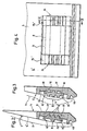
- FIG. 1 to 7 show a first embodiment of a backrest for a motor vehicle seat.
- This has two mirror rails of identical design, which are pivotally connected to a seat frame in a known manner in the area of their lower end in order to adjust the backrest in selectable inclination positions and to be able to determine these positions.
- a crossbeam not shown, extends in the transverse direction of the backrest from the upper end of one longitudinal spar to the corresponding end of the other longitudinal spar 1.
- a sheet metal 3 or one plate made of a different material is At the rear of the frame-like part of the cushion support of the backrest formed from the two longitudinal spars 1 and the crossbar. The lateral edges of the sheet 3 are firmly connected to the longitudinal bars 1, which are designed as metallic profile rails, so that the upholstery support has the shape of a shell.
- a support element 4 is arranged symmetrically to them, which consists of polystyrene rigid foam and is fixed on the sheet 3.
- the carrier element 4, which has the shape of a rectangular plate, is provided in its lower half with a rectangular recess 5, which ends both at a distance from the lower edge and at the same distance from the two lateral edges of the carrier element.
- the recess 5 lies in the area of the backrest aligned with the upper edge of the pelvis and the lumbar vertebrae.
- the backrest has padded side cheeks 6, which are carried by one or the other longitudinal spar 1 and rest against the sheet metal 3 with their back.
- the width of the carrier element 4, as also shown in FIG. 1, is chosen so that it fills the space between the side cheeks 6. Its front side 4 ′ facing the back of the seat user therefore forms the contact surface for the middle part 7 of the backrest upholstery which is provided with a cover and which laterally adjoins the side cheeks 6.
- the carrier element 4 has a wedge-like longitudinal profile. This longitudinal profile is chosen so that the back of the seat user receives orthopedic support and the backrest forms the required lumbar support.
- a molded body 8 which is also made of rigid polystyrene foam is provided in the exemplary embodiment and is inserted into the depression 5 and in this area, i.e. that is, at the level of the lumbar vertebrae and the upper edge of the pelvis, the longitudinal profile of the backrest is determined.
- the molded body 8 has a parallelepiped-shaped central part 9 with a cross-sectional area, which consists of a rectangle and each trapezoid adjoining opposite sides of the rectangle.
- Identical end sections 10 are connected in one piece to the two end faces of the central part 9 which have the same shape. 5 and 6, these end sections 10 have the shape of a rectangular plate, on the two opposite large side surfaces of which strips 11 and 12 are integrally formed. These strips 11 and 12 all have the same trapezoidal cross-sectional profile and extend from the central part 9 to the exposed end face of the end section 10.
- three strips 11 are provided on one side at equal intervals next to one another, while the other side has only a single strip 12 which is aligned with the middle of the strips 11, however could also have a different position.
- the end sections 10 are offset from the center plane against one of the two support surfaces 13 or 14 of the center part 9, which, depending on how the molded body 8 is inserted into the recess 5, of the system serve the middle part 7 of the cushion.
- the two support surfaces 13 and 14 have the same shape and produce a weakly trapezoidal profile
- the longitudinal profile of the backrest in the region determined by the molded body 8 depends on this offset, whether the support surface 13 or the Support surface 14 is facing the back of the seat user. In the latter case, the curvature of the longitudinal profile caused by the molded body 8 against the back of the seat user is significantly greater than when the support surface 13 faces the back of the seat user.
- the depression 5 is designed as an opening in its central region receiving the central part 9 of the molded body 8. Whose dimension in the transverse direction of the backrest is adapted to the corresponding dimension of the middle part 9 of the molded body 8. On the other hand, the dimension of the opening in the vertical extension of the backrest is greater than the corresponding dimension of the molded body 8, which also applies to the two side regions of the recess 5, so that the molded body 8 can be inserted into the recess 5 at different heights.
- the two identically designed side regions 15 of the recess 5 are adapted in their width measured in the transverse direction of the backrest to the width of the end sections 10 measured in this direction.
- the molded body 8 is therefore secured against displacement in the transverse direction of the backrest when it engages in the recess 5.
- the recessed support surface 15 'facing the back of the seat user is provided with three grooves 16, the cross-sectional profile of which is adapted to the cross-sectional profile of the strips 11 and 12.
- the spacing of these grooves 16 running in the transverse direction of the backrest is selected in accordance with the spacing of the strips 11 from one another.
- the molded body 8 can only be inserted into the recess 5 at a single height adjustment. If, on the other hand, the support surface 14 faces the back of the seat user, then the strip 12 can optionally be inserted into one of the three grooves 16, in which case the contact surface 18 bearing this strip rests on the contact surface 15 '. This means that in order to achieve a greater arching of the longitudinal profile in the area of the lumbar vertebrae and the upper edge of the pelvis, the height of the shaped body 8 can be changed in three stages and thus adapted to different needs.
- the pad 7, as shown in FIG. 2, has a crease line 7 'extending slightly above the upper edge of the recess 5 and extending across the entire width of the pad, which in the exemplary embodiment is formed by a transverse seam. From this water bend line 7 'to the lower end, the cushion 7 is not connected along its two lateral edges to the carrier element 4 or the cushion carrier, not shown. > n is a strip-shaped fastener element 19 attached along the lower edge of the cushion 7, which together with a corresponding adhesive fastener element which is attached to the front of the carrier element 4 and aligned with the fastener element 19, a releasable connection between the cushion 7 and the carrier element 4 results.
- the cushion 7 In order to gain access to the molded body 8, the cushion 7 only needs to be detached from the carrier element 4 at its lower edge and then to be folded forward and upward about the fold line 7 '.
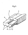
- a first essential difference of the second exemplary embodiment from the first exemplary embodiment according to FIGS. 1 to 7 is that the carrier element 104 has two depressions 105 which are each arranged symmetrically to the longitudinal center line and at a mutual distance from one another, which are of identical design and in each of which a molded body 108 can be used.
- the two depressions 105 which penetrate the carrier element 104 continuously over a large part of their length, lie in the region of the backrest which is aligned with the upper edge of the pool and adjoins it upwards.
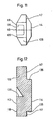
- the shape of the recesses 105 is adapted to the shape of the contour surface of the molded body 108. As can be seen from FIG.
- this contour surface is composed of a central, elongated rectangular surface with trapezoidal surfaces adjoining it on both sides, the longer, parallel sides of the trapezoidal surfaces coinciding with the short sides of the central rectangular surface.
- the depressions 105 are not designed to be continuous over their entire length, but instead have in the lateral end regions the bottoms 131 forming the bottom of the depression 105 and a central rib 132 running transversely at the bottom of the depression 105.
- the contour surface of the lateral bottoms 131 corresponds to the trapezoidal surface of the lateral end regions of the shaped bodies 108.
- the surfaces of the bottoms 131 and the rib 132 facing the associated molded body 108 lie in a common plane with each recess 105 and serve as contact surfaces 115 ', on which are assigned Support contact surfaces of the molded body 108 inserted into the relevant depression.
- Each shaped body 108 has a cuboid middle part 109 with a cross-sectional area, which consists of a rectangle and a trapezoid adjoining opposite sides of the rectangle. If the molded body 108 is inserted into the relevant recess 105 in such a position that its support surface 113 faces the upholstery of the backrest, the molded body 108 rests with contact surfaces 117 on the contact surfaces 115 'of the recess 105.
- the contact surfaces 117 are formed by the base of a central, transverse groove 135, which is machined into the support surface 114 of the molded body 108, and by lateral recesses 136 at the end regions of the molded body.
- the contact surfaces 117 of the lateral recesses 136 bear against the contact surfaces 115 'of the bottoms 131, and the contact surface 117 of the groove 135 lies against the contact surface 115' of the rib 132, which is received in the groove 135.
- the support surface 113 is inserted into the relevant recess 105 in the other position in which its support surface 114 faces the upholstery of the backrest, the support surface 113, at the same time serving as contact surface 118, bears against the contact surface 115 'of the relevant recess 105 .
- the contact surface 117 is offset inwards relative to the support surface 114 of the molded body 108, while the other contact surface 118 coincides with the support surface 113. Because of this offset, the longitudinal profile of the backrest in the area determined by the molded body 108 depends on whether the support surface 114 or the support surface 113 is the upholstery of the backrest, i.e. the back of the seat user.
- the removal of the molded body 108 presents no difficulties because it is gripped comfortably by engaging in the central groove 135 and one of the lateral recesses 136 can be.
- two grip holes 138 are provided in the support surface 113, one of which is in each case is arranged in the vicinity of each lateral end region of the shaped body 108.
- a further essential difference of the exemplary embodiment according to FIGS. 8 to 12 compared to the first described exemplary embodiment consists in the fact that the carrier element 104 has a transverse groove 143 in the area between the two depressions 105 which extends from one side edge 141 to the other side edge 142 of the carrier element 104, which is open to the front, ie to the side of the carrier element 104 facing the seat user.
- the carrier element 104 is formed in two parts and consists of a lower carrier part 151, in which the lower recess 105 is arranged approximately centrally, based on the height dimension of the carrier part 151, and an upper carrier part 152 adjoining this at the top
- the two carrier parts 151 and 152 lie against one another in the region of the base of the groove 143.
- the joint at the base of the groove 143 does not run in a straight line, but in such a way that the upper support part 152 in the areas 154 and 155 adjacent to the side edges 141 and 142 of the support element 104 cover the entire area
- the bottom of the groove 143 forms, while the lower support part 151 is only involved in the formation of the bottom or bottom of the groove 143 in the further inward longitudinal section of the groove 143.
- the groove 143 is provided to receive a crossbar or a shaft connecting the longitudinal bars 1 (FIG. 1) of the cushion support.
Landscapes
- Engineering & Computer Science (AREA)
- Aviation & Aerospace Engineering (AREA)
- Transportation (AREA)
- Mechanical Engineering (AREA)
- Chair Legs, Seat Parts, And Backrests (AREA)
- Mattresses And Other Support Structures For Chairs And Beds (AREA)
- Seats For Vehicles (AREA)
Claims (22)
- Dossier pour un siège de véhicule, notamment un siège de véhicule automobile, dont un support de rembourrage (3,4) comporte, sur le côté tourné ves l'utilisateur du siège, un profil longitudinal réglable à l'aide d'au moins un corps profilé (8, 108) ayant une forme invariante, caractérisé en ce que le corps profilé (8; 108) comporte, aussi bien du côté tourné vers le rembourrage (7) que du côté opposé au rembourrage (7), respectivement une surface d'application (17,18; 117,118), qui vient s'appliquer sélectivement dans des positions définies du corps profilé (8; 108) par rapport au support de rembourrage, contre une surface d'appui respective (15; 115) d'un élément porteur (4; 104) et en ce que, lors d'une application d'une des surfaces d'appui (17; 117) contre la surface d'appui (15'; 115') de l'élément porteur (4; 104), le profil longitudinal du support de rembourrage, formé par la surface de soutien (13, 14; 113,114) tournée vers le rembourrage (7), est différent du profil établi lors d'une application de l'autre surface d'application (18; 118) contre la surface d'appui (15'; 115').
- 2. - Dossier selon la revendication 1, caractérisé en ce que le profil longitudinal du support de rembourrage, défini lors d'une application d'une des surfaces d'application (18; 118) contre la surface d'appui (15'; 115') présente une plus forte courbure initiale en direction du dos de l'utilisateur du siège que lors d'une application de l'autre surface d'application (17; 117).
- 3. - Dossier selon une des revendications 1 ou 2, caractérisé en ce que l'élément porteur (4; 104) formant une partie du support de rembourrage est un corps en forme de plaque dont la surface de soutien tournée vers le rembourrage est profilée, à l'exception de sa zone (5; 105) tournée vers le corps profilé (8; 108), en correspondance au profil longitudinal désiré du support de rembourrage.
- 4. - Dossier selon la revendication 3, caractérisé en ce que la zone de l'élément porteur (4; 104) qui est recouverte par le corps profilé (8; 108) est agencée sous la forme d'au moins un creux (5; 105) recevant le corps profilé correspondant (8; 108).
- 5. - Dossier selon la revendication 4, caractérisé en ce que l'élément porteur (104) comporte deux creux (105) ayant un profil identique au moins dans l'essentiel, tourné l'un vers l'autre et décalés mutuellement dans le sens de la hauteur du dossier, pour recevoir chacun un des deux corps profilés (108) de structure identique.
- 6. - Dossier selon une quelconque des revendications 1 à 5, caractérisé en ce que les deux surfaces d'application (17, 18) de chaque corps profilé (8) sont placées dans la zone des deux parties extrêmes latérales (10) de ce corps et comportent des éléments d'arrêt (11, 12) qui coopèrent avec des éléments d'arrêt (16) prévus dans la zone de la surface d'appui (15').
- 7. - Dossier selon la revendication 6, caractérisé en ce que les éléments d'arrêt s'accrochant l'un dans l'autre sont agencés sous forme de moulures (11, 12) et de rainures (16) orientées dans une direction transversale du dossier et qui ont avantageusement une section profilée en forme de trapèze.
- 8. - Dossier selon la revendication 7, caractérisé en ce que les moulures (11,12) et les rainurés (16) peuvent être mutuellement emboîtées au moins lors d'une application d'une des surfaces d'application (18) contre la surface d'appui (15') à différentes hauteurs de réglage de chaque corps profilé (8).
- 9. - Dossier selon une quelconque des revendications 4 à 8, caractérisé en ce que chaque creux (5) a la forme d'un rectangle s'étendant dans une direction transversale du dossier et en ce que les surfaces d'appui (15') placées en retrait sont constituées par les zones extrêmes latérales du creux (5).
- 10. - Dossier selon la revendication 9, caractérisé en ce que le corps profilé (8) a un contour rectangulaire correspondant à la forme du creux (5) et la largeur des parties extrêmes latérales (10) qui constituent les surfaces d'application (17, 18) placées en retrait est adaptée à la largeur des zones marginales.
- 11. - Dossier selon une des revendications 9 ou 10, caractérisé en ce qu'il est prévu dans chacune des deux zones marginales latérales trois rainures (16) et en ce que les parties extrêmes latérales (10) du corps profilé (8) comportent sur un de leurs côtés trois moulures (11) et sur l'autre côté une moulure (12).
- 12. - Dossier selon la revendication 5, caractérisé en ce que chaque creux (105) a la forme d'un rectangle s'étendant dans une direction transversale du dossier et comportant des zones extrêmes latérales ayant de préférence une forme de trapèze et en ce que la surface d'appui (115') placée en retrait est constituée par les fonds (131) définissant la base du creux (105), dans les deux zones extrêmes latérales du creux (105) ainsi que par la surface, située dans un même plan, d'une nervure (132) disposée transversalement dans une zone centrale du creux (105).
- 13. - Dossier selon la revendication 12, caractérisé en ce que chaque corps profilé (108) a un contour et une grandeur correspondant aux deux creux (105), en ce qu'une surface d'application (118) prévue pour coopérer avec la surface d'appui (115') est constituée par une des surfaces de soutien (113) du corps profilé (108) et en ce que l'autre surface d'application (117) du corps profilé (108) est constituée par le fond d'une rainure transversale (135) prévue pour recevoir la nervure (132) et ménagée dans l'autre surface de soutien (114) prévue dans la partie centrale (108) du corps profilé (108) ainsi que par des surfaces, placées en retrait et dans un plan commun avec le fond de la rainure (135), d'évidements (136) ménagés dans les zones extrêmes latérales du corps profilé (108).
- 14. - Dossier selon la revendication 13, caractérisé en ce que des trous de préhension (138) sont ménagés dans une surface de soutien (113) du corps profilé (108) servant de surface d'appui (118).
- 15. - Dossier selon une quelconque des revendications 1 à 14, caractérisé en ce que le corps profilé (8; 108) et l'élément porteur (4; 104) sont constitués d'une matière plastique, de préférence d'une mousse dure de polystyrène.
- 16. - Dossier selon une quelconque des revendications 1 à 15, caractérisé en ce que le rembourrage (7) est relié de façon séparable, dans une zone de l'élément porteur (4; 104) avec celui-ci ou avec le support de rembourrage.
- 17. - Dossier selon la revendication 16, caractérisé en ce que, pour établir la liaison séparable, il est prévu un élément de fermeture par adhérence (19) ou bien une fermeture à glissière.
- 18. - Dossier selon la revendication 17, caractérisé en ce que le rembourrage (7) ne presénte aucune liaison avec l'élément porteur (4; 104) ou avec le support de rembourrage latéralement depuis son bord inférieur jusqu'à une hauteur placée au-dessus du bord supérieur du corps profilé (8; 108) placé complètement en haut.
- 19. - Dossier selon une quelconque des revendications 16 à 18, caractérisé en ce qu'il est prévu une ligne de pliage (7') du rembourrage (7) s'étendant transversalement au-dessus du rembourrage (7).
- 20. - Dossier selon une quelconque des revendications 1 à 19, caractérisé en ce qu'il est prévu dans l'élément porteur (104) une rainure continue (143) s'étendant d'un bord latéral (141) à l'autre bord latéral (142) de celui-ci et ouverte en direction du rembourrage (7).
- 21. - Dossier selon une des revendications 5 et 20, caractérisé en ce que la rainure (143) est placée dans la zone située entre les deux creux (105).
- 22. - Dossier selon la revendication 21, caractérisé en ce que l'élément porteur (104) est constitué d'une partie inférieure de support (151) en forme de plaque comportant un des deux creux (105) et d'une partie supérieure de support (152) reliée à l'extrémité supérieure de la première partie et comportant l'autre creux (105).
Applications Claiming Priority (2)
| Application Number | Priority Date | Filing Date | Title |
|---|---|---|---|
| DE3222951 | 1982-06-18 | ||
| DE3222951A DE3222951C2 (de) | 1982-06-18 | 1982-06-18 | Rückenlehne für einen Fahrzeugsitz, insbesondere einen Kraftfahrzeugsitz |
Publications (3)
| Publication Number | Publication Date |
|---|---|
| EP0103679A2 EP0103679A2 (fr) | 1984-03-28 |
| EP0103679A3 EP0103679A3 (en) | 1985-01-09 |
| EP0103679B1 true EP0103679B1 (fr) | 1986-09-03 |
Family
ID=6166371
Family Applications (1)
| Application Number | Title | Priority Date | Filing Date |
|---|---|---|---|
| EP83105844A Expired EP0103679B1 (fr) | 1982-06-18 | 1983-06-15 | Dossier pour siège de véhicule, notamment pour siège de véhicule automobile |
Country Status (4)
| Country | Link |
|---|---|
| US (1) | US4555137A (fr) |
| EP (1) | EP0103679B1 (fr) |
| JP (1) | JPS5957036A (fr) |
| DE (2) | DE3222951C2 (fr) |
Cited By (1)
| Publication number | Priority date | Publication date | Assignee | Title |
|---|---|---|---|---|
| DE102005013613B4 (de) * | 2005-03-24 | 2010-06-17 | Faurecia Autositze Gmbh | Kraftfahrzeugsitz |
Families Citing this family (20)
| Publication number | Priority date | Publication date | Assignee | Title |
|---|---|---|---|---|
| JPS62128844A (ja) * | 1985-11-29 | 1987-06-11 | Aprica Kassai Inc | 自動車用子供安全シート |
| US4728148A (en) * | 1986-12-08 | 1988-03-01 | Tachi-S Co., Ltd. | Supporting structure of the lumbar portion of the foam cushion member in an automotive seat |
| US4810034A (en) * | 1987-11-27 | 1989-03-07 | Beier John K | Backrest with adjustable lumber support |
| US4834455A (en) * | 1988-07-14 | 1989-05-30 | Proctor Joy E | Orthopedic vehicle seat |
| IT1232129B (it) * | 1989-07-05 | 1992-01-23 | Fiat Auto Spa | Schienale di sedile a struttura stratificata |
| US5474362A (en) * | 1991-06-26 | 1995-12-12 | Albecker, Iii; Walter J. | Cushions having internal support member |
| US5370444A (en) * | 1992-09-11 | 1994-12-06 | Sears Manufacturing Company | Adjustable cushion |
| FR2696383B1 (fr) * | 1992-10-02 | 1994-12-09 | France Design | Siège de véhicule et véhicule muni de tels sièges. |
| DE19510789C2 (de) * | 1995-03-24 | 2002-07-18 | Johnson Controls Naue Engineer | Fahrzeugsitz mit auswechselbaren seitlichen Stützpolstern am Sitzkissen und an der Rückenlehne |
| DE19751091A1 (de) * | 1997-11-18 | 1999-05-20 | Bayerische Motoren Werke Ag | Fahrzeugsitz mit modularem Polsteraufbau |
| EP0970639A1 (fr) * | 1998-07-07 | 2000-01-12 | Provenda Marketing Ag | Support lombaire réglable |
| DE10014164A1 (de) * | 2000-03-23 | 2001-10-04 | Haworth Bueroeinrichtung Gmbh | Stuhl mit einer ein höhenverstellbares Lordosenteil aufweisenden Rückenlehne |
| DE10227946A1 (de) * | 2002-06-22 | 2004-03-04 | Adam Opel Ag | Fahrzeugsitzanordnung |
| DE102005012320A1 (de) | 2005-03-17 | 2006-09-21 | Faurecia Autositze Gmbh & Co. Kg | Kraftfahrzeugsitz |
| US8118359B2 (en) * | 2008-10-14 | 2012-02-21 | Honda Motor Co., Ltd. | Vehicle seat |
| US8485603B2 (en) * | 2010-03-12 | 2013-07-16 | Walter Albecker | Loose fill cushions having internal support member |
| JP5582500B2 (ja) * | 2010-07-18 | 2014-09-03 | 株式会社デルタツーリング | ランバー支持部材、輸送機器用座席構造及びシート用クッション |
| JP6594172B2 (ja) * | 2015-11-17 | 2019-10-23 | 株式会社タチエス | 車両用シート |
| US9868374B2 (en) * | 2016-03-18 | 2018-01-16 | Ami Industries, Inc. | Modular monocoque backrest |
| JP7644728B2 (ja) * | 2022-02-22 | 2025-03-12 | 株式会社タチエス | 車両用シート |
Family Cites Families (10)
| Publication number | Priority date | Publication date | Assignee | Title |
|---|---|---|---|---|
| US2894565A (en) * | 1957-05-17 | 1959-07-14 | Hubert R Crane | Contouring back rest for motor vehicle seats |
| DE1160316B (de) * | 1957-10-23 | 1963-12-27 | Daimler Benz Ag | Sessel, vornehmlich fuer Kraftfahrzeuge |
| DE1554084C3 (de) * | 1966-11-29 | 1975-04-24 | Recaro Gmbh & Co, 7000 Stuttgart | Sitz, insbesondere Kraftfahrzeugsitz |
| JPS4920611U (fr) * | 1972-05-26 | 1974-02-21 | ||
| JPS5074623U (fr) * | 1973-11-13 | 1975-06-30 | ||
| US3990742A (en) * | 1975-07-03 | 1976-11-09 | Glass Katalina T | Adjustable spinal contour seating |
| US4097087A (en) * | 1977-05-13 | 1978-06-27 | Garavaglia Marco F | Chair with adjustable back support cushion |
| JPS55122660U (fr) * | 1979-02-22 | 1980-09-01 | ||
| US4295681A (en) * | 1980-02-19 | 1981-10-20 | Uop Inc. | Seat having lumbar support and vertical height adjustment mechanism therefor |
| JPS5745355U (fr) * | 1980-08-29 | 1982-03-12 |
-
1982
- 1982-06-18 DE DE3222951A patent/DE3222951C2/de not_active Expired
-
1983
- 1983-06-15 EP EP83105844A patent/EP0103679B1/fr not_active Expired
- 1983-06-15 DE DE8383105844T patent/DE3365856D1/de not_active Expired
- 1983-06-17 JP JP58107996A patent/JPS5957036A/ja active Granted
- 1983-06-20 US US06/505,921 patent/US4555137A/en not_active Expired - Fee Related
Cited By (1)
| Publication number | Priority date | Publication date | Assignee | Title |
|---|---|---|---|---|
| DE102005013613B4 (de) * | 2005-03-24 | 2010-06-17 | Faurecia Autositze Gmbh | Kraftfahrzeugsitz |
Also Published As
| Publication number | Publication date |
|---|---|
| DE3222951C2 (de) | 1985-10-24 |
| JPS5957036A (ja) | 1984-04-02 |
| DE3365856D1 (en) | 1986-10-09 |
| EP0103679A2 (fr) | 1984-03-28 |
| DE3222951A1 (de) | 1983-12-22 |
| JPH028931B2 (fr) | 1990-02-27 |
| EP0103679A3 (en) | 1985-01-09 |
| US4555137A (en) | 1985-11-26 |
Similar Documents
| Publication | Publication Date | Title |
|---|---|---|
| EP0103679A2 (fr) | Dossier pour siège de véhicule, notamment pour siège de véhicule automobile | |
| DE2733744C2 (fr) | ||
| DE1554084C3 (de) | Sitz, insbesondere Kraftfahrzeugsitz | |
| DE69402438T2 (de) | Haltevorrichtung für die Kanten der Sitzkissenbezüge | |
| DE2064419C3 (de) | Rückenlehne für Kraftfahrzeugsitze | |
| EP3392119B1 (fr) | Support de bouteilles et unité de support de bouteilles | |
| DE3046427A1 (de) | Rueckenlehne fuer einen fahrzeugsitz | |
| DE8125124U1 (de) | Diapositivrahmen | |
| EP3626317A1 (fr) | But | |
| DE3604463C2 (de) | Sicherheitssitz für Kinder in Kraftfahrzeugen | |
| DE69209483T2 (de) | Behälter mit dreifacher Stapelmöglichkeit | |
| DE69100905T2 (de) | Lattenrost. | |
| DE29624278U1 (de) | Matratzenunterlage mit federnden Schaumstoffblöcken | |
| EP0064754B1 (fr) | Dispositif de support pour prospectus et articles plats analogues | |
| EP0873705B1 (fr) | Raccordement d'un panneau de séparation à l'aide d'un rail pour la réception et le support d'objets | |
| WO1997048087A1 (fr) | Support pour panneaux pivotants ou similaire | |
| DE668656C (de) | Schuhabstreifmatte mit feststehenden Buersten | |
| DE3407109A1 (de) | Sicherheitssitz fuer kinder in kraftfahrzeugen | |
| DE29520420U1 (de) | Scherkopf für einen Rasierer | |
| CH644742A5 (en) | Partitioning device for drawers | |
| DE8601621U1 (de) | Autositzbezug | |
| EP0127779A2 (fr) | Panneau de fond pour cadres de tableaux | |
| DE9108092U1 (de) | Vorrichtung zum Erfassen und Berechnen von geometrischen Umfangslinien und Flächen | |
| DE2513955B2 (de) | Bettuchhalter | |
| DE2435743B2 (de) | Passierhobel für Spätzleteig |
Legal Events
| Date | Code | Title | Description |
|---|---|---|---|
| PUAI | Public reference made under article 153(3) epc to a published international application that has entered the european phase |
Free format text: ORIGINAL CODE: 0009012 |
|
| AK | Designated contracting states |
Designated state(s): DE FR GB IT |
|
| PUAL | Search report despatched |
Free format text: ORIGINAL CODE: 0009013 |
|
| AK | Designated contracting states |
Designated state(s): DE FR GB IT |
|
| 17P | Request for examination filed |
Effective date: 19841229 |
|
| ITF | It: translation for a ep patent filed | ||
| GRAA | (expected) grant |
Free format text: ORIGINAL CODE: 0009210 |
|
| AK | Designated contracting states |
Kind code of ref document: B1 Designated state(s): DE FR GB IT |
|
| REF | Corresponds to: |
Ref document number: 3365856 Country of ref document: DE Date of ref document: 19861009 |
|
| ET | Fr: translation filed | ||
| PLBE | No opposition filed within time limit |
Free format text: ORIGINAL CODE: 0009261 |
|
| STAA | Information on the status of an ep patent application or granted ep patent |
Free format text: STATUS: NO OPPOSITION FILED WITHIN TIME LIMIT |
|
| 26N | No opposition filed | ||
| PGFP | Annual fee paid to national office [announced via postgrant information from national office to epo] |
Ref country code: FR Payment date: 19920526 Year of fee payment: 10 |
|
| PGFP | Annual fee paid to national office [announced via postgrant information from national office to epo] |
Ref country code: GB Payment date: 19920601 Year of fee payment: 10 |
|
| ITTA | It: last paid annual fee | ||
| PG25 | Lapsed in a contracting state [announced via postgrant information from national office to epo] |
Ref country code: GB Effective date: 19930615 |
|
| GBPC | Gb: european patent ceased through non-payment of renewal fee |
Effective date: 19930615 |
|
| PG25 | Lapsed in a contracting state [announced via postgrant information from national office to epo] |
Ref country code: FR Effective date: 19940228 |
|
| REG | Reference to a national code |
Ref country code: FR Ref legal event code: ST |
|
| PGFP | Annual fee paid to national office [announced via postgrant information from national office to epo] |
Ref country code: DE Payment date: 19950623 Year of fee payment: 13 |
|
| PG25 | Lapsed in a contracting state [announced via postgrant information from national office to epo] |
Ref country code: DE Effective date: 19970301 |