EP0103692A2 - Machine à combustion interne à piston avec équilibrage des masses et des moments - Google Patents
Machine à combustion interne à piston avec équilibrage des masses et des moments Download PDFInfo
- Publication number
- EP0103692A2 EP0103692A2 EP83106819A EP83106819A EP0103692A2 EP 0103692 A2 EP0103692 A2 EP 0103692A2 EP 83106819 A EP83106819 A EP 83106819A EP 83106819 A EP83106819 A EP 83106819A EP 0103692 A2 EP0103692 A2 EP 0103692A2
- Authority
- EP
- European Patent Office
- Prior art keywords
- auxiliary
- mass
- masses
- moments
- internal combustion
- Prior art date
- Legal status (The legal status is an assumption and is not a legal conclusion. Google has not performed a legal analysis and makes no representation as to the accuracy of the status listed.)
- Withdrawn
Links
Images




Classifications
-
- F—MECHANICAL ENGINEERING; LIGHTING; HEATING; WEAPONS; BLASTING
- F02—COMBUSTION ENGINES; HOT-GAS OR COMBUSTION-PRODUCT ENGINE PLANTS
- F02B—INTERNAL-COMBUSTION PISTON ENGINES; COMBUSTION ENGINES IN GENERAL
- F02B75/00—Other engines
- F02B75/06—Engines with means for equalising torque
-
- F—MECHANICAL ENGINEERING; LIGHTING; HEATING; WEAPONS; BLASTING
- F16—ENGINEERING ELEMENTS AND UNITS; GENERAL MEASURES FOR PRODUCING AND MAINTAINING EFFECTIVE FUNCTIONING OF MACHINES OR INSTALLATIONS; THERMAL INSULATION IN GENERAL
- F16F—SPRINGS; SHOCK-ABSORBERS; MEANS FOR DAMPING VIBRATION
- F16F7/00—Vibration-dampers; Shock-absorbers
- F16F7/10—Vibration-dampers; Shock-absorbers using inertia effect
- F16F7/104—Vibration-dampers; Shock-absorbers using inertia effect the inertia member being resiliently mounted
- F16F7/108—Vibration-dampers; Shock-absorbers using inertia effect the inertia member being resiliently mounted on plastics springs
-
- F—MECHANICAL ENGINEERING; LIGHTING; HEATING; WEAPONS; BLASTING
- F16—ENGINEERING ELEMENTS AND UNITS; GENERAL MEASURES FOR PRODUCING AND MAINTAINING EFFECTIVE FUNCTIONING OF MACHINES OR INSTALLATIONS; THERMAL INSULATION IN GENERAL
- F16F—SPRINGS; SHOCK-ABSORBERS; MEANS FOR DAMPING VIBRATION
- F16F7/00—Vibration-dampers; Shock-absorbers
- F16F7/10—Vibration-dampers; Shock-absorbers using inertia effect
- F16F7/104—Vibration-dampers; Shock-absorbers using inertia effect the inertia member being resiliently mounted
- F16F7/116—Vibration-dampers; Shock-absorbers using inertia effect the inertia member being resiliently mounted on metal springs
Definitions
- the invention relates to a device for balancing inertial forces and moments on reciprocating internal combustion engines.
- the object of the present invention is to compensate for the inertial forces and moments on reciprocating internal combustion engines, but a much lower construction effort is sought, which provides a reliable compensation of the forces and moments with considerably lower costs.
- the object of the invention is achieved in that vibratable auxiliary masses are fastened at a suitable point or suitable points on the reciprocating piston internal combustion engine and are supported resiliently in the direction of the mass forces or mass moments to be compensated.
- the springs By appropriate design of the springs as well as the size of the masses and their articulation direction, it is advantageously possible to suppress the mass forces and mass moments.
- the proposal according to the invention applies without any restrictions if, for example, the reciprocating piston internal combustion engine rotates continuously or mostly at a predetermined constant speed. Then the occurring mass forces and mass moments can be completely exactly balanced, since the mass forces and mass moments have a certain oscillation frequency and a certain amplitude, to which the auxiliary masses, the springs and the linkage can be adapted exactly.
- a good balance of the inertial forces and moments of inertia even with reciprocating internal combustion engines with a wide speed range is possible according to the invention in that in addition to the springs, parallel dampers are provided, through which the frequency range in which the auxiliary masses are effective can be significantly expanded.
- the springs and dampers can be combined to form elastic spring-damper elements, for example rubber elements.
- the mass and momentum compensation according to the invention by the ilfsmassen H is independent of the type and construction of the reciprocating internal combustion engine.
- the mass balance is possible both in series and in V-engines, of single-cylinder multi-cylinder H to ubkolbenbrennkraftmaschi- nen and air or water cooling in the same way.
- the auxiliary masses can be attached in the area of the cylinder heads, in the area of the cylinder tubes or the machine frame or in the area of the crankcase.
- auxiliary masses are arranged in the region of the cylinder feet inside or outside the crankcase. This can be done structurally in a simple manner. In addition, the cooling requirement in this area of the cylinder tubes is also lower, so that the auxiliary masses can be accommodated there without further ado. You can be combined into a plate-shaped mass with recesses for the cylinder tubes, and form a compact unit.
- the V-space of reciprocating piston internal combustion engines with a V-arrangement of the cylinders is also well suited for receiving the auxiliary masses or an auxiliary mass.
- auxiliary mass or auxiliary masses can also be arranged below the axis of rotation of the crankshaft inside or outside the crankcase or on the oil pan.
- the mass or masses can be attached to the bearing blocks of the main bearing of the crankshaft.
- the auxiliary mass or auxiliary masses can also be annular, designed as a half or full ring and arranged in the end regions of the reciprocating piston internal combustion engine, in particular coaxially to the crankshaft.
- both inertial forces and inertial moments can be absorbed.
- the auxiliary masses which are preferably designed as a full ring, can also be supported in a ring.
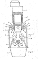
- 1 denotes a reciprocating piston internal combustion engine, which functions with a crankshaft 2, connecting rod 3, piston 4, cylinder tube 5, cylinder head 6 , Crankcase 7, Käbwellenwellenboothen 8 and an oil pan 9 is provided.
- a device 10 for compensating mass forces and mass moments is arranged on the outside of the crankcase 7, said auxiliary mass consisting of vibratable auxiliary masses 11 which are supported in the direction of the mass forces or mass moments to be compensated for - here parallel to the piston longitudinal axis.
- the support is provided via elastic rubber members 12, whereby the elasticity of the rubber elements 12, and hence the frequency range in which the H ilfsmassen be effectively 11, is adapted to the speed range of the reciprocating internal combustion engine.
- the arrangement of the compensating device 10 shown in this exemplary embodiment outside the crankcase 7 in the region of the cylinder feet 5a of the cylinder tube 5 can be structurally accomplished in a simple manner and has an insignificant effect on the cooling air flow in the case of air cooling of the reciprocating piston internal combustion engine 1.
- the device 10 for compensating the inertial forces or inertial moments is arranged within the crankcase 7.
- the auxiliary mass 11 are combined to form a plate-shaped mass and have a recess 13 for the cylinder tube 5 on.
- the H ilfsmassen 11 are connected in parallel F e-countries 14 and damper 15 with interposition of a member 16 attached to the crankcase 7.
- the auxiliary masses 11 are arranged below the axis of rotation of the crankshaft 2 within the crankcase 7 or the oil pan 9 and are fastened to the bearing blocks 8 of the main bearings of the crankshaft 2 via screw connections 17.
- the auxiliary masses 11 of the individual cylinders of the reciprocating piston internal combustion engine are combined as a plate-shaped total mass and provided with cutouts 18 which ensure an unobstructed rotational movement of the crankshaft 2 or the connecting rods 3 even in the vibrating state of the auxiliary masses 11.
- the auxiliary masses 11 are again supported via springs 14 and dampers 15 and via components 16 which are screwed onto the bearing blocks.
- FIG. 5 shows a reciprocating piston internal combustion engine 1 with rows of cylinders arranged in a V-shape.
- the device 10 for compensating the inertial forces or moments in the V-space 19 is provided within the crankcase 7.
- the auxiliary mass 11 is supported by springs 14 and dampers 15 and components 16 on the horizontal cover 20 of the V-space 19.
- the springs 14 and the dampers 15 are supported here in different directions; a spring is perpendicular to the cover 20, two springs 14 are supported parallel to the cover 20 and the dampers 15 are each supported parallel to the longitudinal axis of the piston 4, so that differently directed force components can be easily compensated in two-dimensional space.
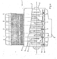
- Fig. 6 shows schematically a sectionlp.ngsterrorism a reciprocating internal combustion engine, in which the H ilfsmassen 11 are formed as full rings and are arranged at the end regions 21 of the reciprocating internal combustion engine 1 coaxially with the crankshaft 2.
- the support is provided via a likewise annular rubber element 12 and via an annular component 16 on a main bearing block 8 of the crankshaft 2.
- an annular component of the crankcase can of course also be used. This embodiment is particularly important for the compensation of tilting and longitudinal moments of a reciprocating piston internal combustion engine.
Landscapes
- Engineering & Computer Science (AREA)
- General Engineering & Computer Science (AREA)
- Mechanical Engineering (AREA)
- Chemical & Material Sciences (AREA)
- Combustion & Propulsion (AREA)
- Shafts, Cranks, Connecting Bars, And Related Bearings (AREA)
- Cylinder Crankcases Of Internal Combustion Engines (AREA)
- Lubrication Details And Ventilation Of Internal Combustion Engines (AREA)
- Vibration Prevention Devices (AREA)
Applications Claiming Priority (2)
| Application Number | Priority Date | Filing Date | Title |
|---|---|---|---|
| DE19823234980 DE3234980A1 (de) | 1982-09-22 | 1982-09-22 | Hubkolbenbrennkraftmaschine mit massen- bzw. momentausgleich |
| DE3234980 | 1982-09-22 |
Publications (2)
| Publication Number | Publication Date |
|---|---|
| EP0103692A2 true EP0103692A2 (fr) | 1984-03-28 |
| EP0103692A3 EP0103692A3 (fr) | 1985-01-09 |
Family
ID=6173792
Family Applications (1)
| Application Number | Title | Priority Date | Filing Date |
|---|---|---|---|
| EP83106819A Withdrawn EP0103692A3 (fr) | 1982-09-22 | 1983-07-12 | Machine à combustion interne à piston avec équilibrage des masses et des moments |
Country Status (2)
| Country | Link |
|---|---|
| EP (1) | EP0103692A3 (fr) |
| DE (1) | DE3234980A1 (fr) |
Cited By (4)
| Publication number | Priority date | Publication date | Assignee | Title |
|---|---|---|---|---|
| EP0760422A1 (fr) * | 1995-08-25 | 1997-03-05 | WOCO Franz-Josef Wolf & Co. | Dispositif et procédé pour diminuer la charge de bruit produit par un moteur à combustion interne |
| WO2010112665A1 (fr) * | 2009-03-30 | 2010-10-07 | Wärtsilä Finland Oy | Dispositif et procédé pour atténuer la vibration d'un moteur à piston et moteur à piston |
| EP3499059A1 (fr) * | 2017-12-15 | 2019-06-19 | Toyota Jidosha Kabushiki Kaisha | Ensemble de capuchon de manivelle et moteur à combustion interne |
| WO2019202542A1 (fr) * | 2018-04-18 | 2019-10-24 | North-West University | Amortisseur de vibration de moteur |
Families Citing this family (4)
| Publication number | Priority date | Publication date | Assignee | Title |
|---|---|---|---|---|
| DE4236185A1 (de) * | 1992-10-27 | 1994-04-28 | Freudenberg Carl Fa | Kolbenarbeits- und -kraftmaschine |
| DE4410495A1 (de) * | 1994-03-27 | 1995-09-28 | Schrick Gmbh Dr | Kolbenmaschine mit Ausgleich freier Massenkräfte |
| DE10205399C1 (de) * | 2002-02-09 | 2003-07-03 | Bosch Gmbh Robert | Vorrichtung zur Schwingungsreduktion eines Motors oder Generators |
| DE102015216614A1 (de) * | 2015-08-31 | 2017-03-02 | Volkswagen Aktiengesellschaft | Lagerdeckel für ein zylindrisches Lagerelement einer Kurbelwelle einer Hubkolbenbrennkraftmaschine sowie Hubkolbenbrennkraftmaschine mit Lagerdeckel |
Family Cites Families (13)
| Publication number | Priority date | Publication date | Assignee | Title |
|---|---|---|---|---|
| DE228585C (fr) * | ||||
| US1744218A (en) * | 1928-04-13 | 1930-01-21 | Ford Motor Co | Engine |
| US1819665A (en) * | 1930-01-08 | 1931-08-18 | Vibrachek Company | Vibration reducing device |
| DE612406C (de) * | 1932-04-18 | 1935-04-24 | Herbert Austin | Einrichtung zur Daempfung der Schwingungen einer Brennkraftmaschine |
| GB577356A (en) * | 1943-10-07 | 1946-05-15 | Metalastik Ltd | Improvements relating to vibration dampers |
| FR1142684A (fr) * | 1956-02-15 | 1957-09-20 | Dispositif amortisseur pour véhicules | |
| US3388772A (en) * | 1966-06-16 | 1968-06-18 | Continental Motors Corp | Vibration absorber |
| DE7514380U (de) * | 1975-05-03 | 1975-10-16 | Fendt X & Co | Vorrichtung zur Tilgung von Schwingungen einer Masse |
| DE7607516U1 (de) * | 1976-03-11 | 1976-10-14 | Mueller-Bbm Gmbh, 8033 Planegg | Schwingungstilger zur Dämpfung von breitbandigen Körperschallschwingungen |
| DE2632574C2 (de) * | 1976-07-20 | 1984-01-19 | Mtu Motoren- Und Turbinen-Union Friedrichshafen Gmbh, 7990 Friedrichshafen | Vorrichtung zur Schwingungsdämpfung an Brennkraftmaschinen |
| GB1591096A (en) * | 1977-11-15 | 1981-06-17 | English Electric Co Ltd | Gear boxes |
| JPS55103131A (en) * | 1979-01-30 | 1980-08-07 | Agency Of Ind Science & Technol | Method of absorbing vibration of machine foundation or the like |
| DE3025587A1 (de) * | 1980-07-05 | 1982-10-07 | Uhde Gmbh, 4600 Dortmund | Vorrichtung zum daempfen von schwingungen bei arbeitsmaschinen mit vertikal angeordneter rotorwelle |
-
1982
- 1982-09-22 DE DE19823234980 patent/DE3234980A1/de not_active Withdrawn
-
1983
- 1983-07-12 EP EP83106819A patent/EP0103692A3/fr not_active Withdrawn
Cited By (7)
| Publication number | Priority date | Publication date | Assignee | Title |
|---|---|---|---|---|
| EP0760422A1 (fr) * | 1995-08-25 | 1997-03-05 | WOCO Franz-Josef Wolf & Co. | Dispositif et procédé pour diminuer la charge de bruit produit par un moteur à combustion interne |
| WO2010112665A1 (fr) * | 2009-03-30 | 2010-10-07 | Wärtsilä Finland Oy | Dispositif et procédé pour atténuer la vibration d'un moteur à piston et moteur à piston |
| CN102326012A (zh) * | 2009-03-30 | 2012-01-18 | 瓦锡兰芬兰有限公司 | 用于衰减活塞式发动机的振动的装置和方法以及活塞式发动机 |
| CN102326012B (zh) * | 2009-03-30 | 2013-09-25 | 瓦锡兰芬兰有限公司 | 用于衰减活塞式发动机的振动的装置和方法以及活塞式发动机 |
| EP3499059A1 (fr) * | 2017-12-15 | 2019-06-19 | Toyota Jidosha Kabushiki Kaisha | Ensemble de capuchon de manivelle et moteur à combustion interne |
| WO2019202542A1 (fr) * | 2018-04-18 | 2019-10-24 | North-West University | Amortisseur de vibration de moteur |
| NL2020784B1 (en) * | 2018-04-18 | 2019-10-24 | Univ Northwest | Engine Vibration Absorber |
Also Published As
| Publication number | Publication date |
|---|---|
| DE3234980A1 (de) | 1984-03-22 |
| EP0103692A3 (fr) | 1985-01-09 |
Similar Documents
| Publication | Publication Date | Title |
|---|---|---|
| DE723713C (de) | Einrichtung bei Kurbelwellenkolbenmaschinen, z. B. Brennkraftmaschinen | |
| DE698877C (de) | Ausgleichseinrichtung fuer periodische Kraefte bei mehrzylindrigen Verbrennungskraftmaschinen | |
| DE2822006C2 (fr) | ||
| DE2455667C2 (de) | Vorrichtung zum Ausgleich der oszillierenden Kräfte und Momente zweiter Ordnung für eine Vierzylinder-Reihenhubkolbenmaschine | |
| DE3234980A1 (de) | Hubkolbenbrennkraftmaschine mit massen- bzw. momentausgleich | |
| DE10032095B4 (de) | Kurbeltrieb für eine Brennkraftmaschine | |
| DE60112971T2 (de) | V-type brennkraftmaschine mit einer ungeraden anzahl von zylindern | |
| EP0495021B1 (fr) | Equilibrage des masses pour un moteur alternatif a combustion interne | |
| DE3141025A1 (de) | Massenausgleichsmechanismus fuer vierzylinder-verbrennungsmotoren | |
| DE3040686A1 (de) | Massenausgleichseinrichtung | |
| EP0044313B1 (fr) | Machine a piston | |
| DE2904066A1 (de) | Faecherfoermige kolbenmaschine | |
| DE2447001C2 (de) | Einrichtung zum Ausgleich der Massenkräfte von Hubkolben-Kurbelwellenmaschinen | |
| DE3033803A1 (de) | Mehrzylindrige 4takt-hubkolben-brennkraftmaschine in reihenbauart | |
| DE2757332A1 (de) | Brennkraftmaschine mit kurbeltrieb, insbesondere dieselmotor | |
| AT395204B (de) | Kurbelwelle | |
| DE4003468C2 (de) | Pleuel für Hubkolben-Brennkraftmaschinen mit asymmetrischem Schaftquerschnitt | |
| DE3438805C2 (fr) | ||
| DE3542459C2 (fr) | ||
| DE3903419A1 (de) | Massenausgleichanordnung | |
| DE3034978A1 (de) | Einrichtung zum ausgleich freier massenmomente | |
| DE4042425A1 (de) | Boxermotor, kurbelschleifengetriebe mit schwungmasse, die einen energieschwungakkumulator hat | |
| DE2951092A1 (de) | Hubkolbenmaschine mit massenausgleich | |
| DE615766C (de) | Daempfungseinrichtung fuer kardanisch aufgehaengte Kompasse | |
| DE10240713A1 (de) | Massenausgleichsvorrichtung |
Legal Events
| Date | Code | Title | Description |
|---|---|---|---|
| PUAI | Public reference made under article 153(3) epc to a published international application that has entered the european phase |
Free format text: ORIGINAL CODE: 0009012 |
|
| AK | Designated contracting states |
Designated state(s): DE FR GB IT SE |
|
| PUAL | Search report despatched |
Free format text: ORIGINAL CODE: 0009013 |
|
| AK | Designated contracting states |
Designated state(s): DE FR GB IT SE |
|
| STAA | Information on the status of an ep patent application or granted ep patent |
Free format text: STATUS: THE APPLICATION HAS BEEN WITHDRAWN |
|
| 18W | Application withdrawn |
Withdrawal date: 19841208 |
|
| RIN1 | Information on inventor provided before grant (corrected) |
Inventor name: HONRATH, KURT, DR.-ING. |