EP0103693A2 - Raccordement de fils textiles, procédé et dispositif de raccordement - Google Patents
Raccordement de fils textiles, procédé et dispositif de raccordement Download PDFInfo
- Publication number
- EP0103693A2 EP0103693A2 EP83106844A EP83106844A EP0103693A2 EP 0103693 A2 EP0103693 A2 EP 0103693A2 EP 83106844 A EP83106844 A EP 83106844A EP 83106844 A EP83106844 A EP 83106844A EP 0103693 A2 EP0103693 A2 EP 0103693A2
- Authority
- EP
- European Patent Office
- Prior art keywords
- fiber
- fiber structure
- connection
- clamping device
- wound
- Prior art date
- Legal status (The legal status is an assumption and is not a legal conclusion. Google has not performed a legal analysis and makes no representation as to the accuracy of the status listed.)
- Withdrawn
Links
Images


Classifications
-
- B—PERFORMING OPERATIONS; TRANSPORTING
- B65—CONVEYING; PACKING; STORING; HANDLING THIN OR FILAMENTARY MATERIAL
- B65H—HANDLING THIN OR FILAMENTARY MATERIAL, e.g. SHEETS, WEBS, CABLES
- B65H69/00—Methods of, or devices for, interconnecting successive lengths of material; Knot-tying devices ;Control of the correct working of the interconnecting device
- B65H69/06—Methods of, or devices for, interconnecting successive lengths of material; Knot-tying devices ;Control of the correct working of the interconnecting device by splicing
-
- B—PERFORMING OPERATIONS; TRANSPORTING
- B65—CONVEYING; PACKING; STORING; HANDLING THIN OR FILAMENTARY MATERIAL
- B65H—HANDLING THIN OR FILAMENTARY MATERIAL, e.g. SHEETS, WEBS, CABLES
- B65H2701/00—Handled material; Storage means
- B65H2701/30—Handled filamentary material
- B65H2701/31—Textiles threads or artificial strands of filaments
Definitions
- a disadvantage of known splice connections is that it proves difficult to achieve a reproducibility that is sufficiently the same for practical requirements in a wide range of applications.
- the invention is based on the general idea of a solution to achieve the connection of the two fiber bundles instead of by splicing through a tight, force-locking mutual winding around the two fiber bundles and fixing the winding.
- the task is solved by the measures set out in the claims.
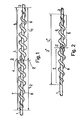
- Fig. 1 shows schematically the principle of the invention based on a first fiber structure 1 and a second Faser concernedes2in a compound 3.
- the compound 3, is a substantially symmetrical to a virtual center Z structure, wherein over a first portion L 1 of the length L of the Connection 3 is part of the first fiber structure 1 around the second fiber structure 2 is wound and in a second part L 2 of the length L of the connection 3 a part of the second fiber structure 2 is wound around the first fiber structure 1.
- the fiber beards 6 and 8 at least partially establish a non-positive connection with individual fibers emerging from the respective other fiber structure that is wrapped around each other.
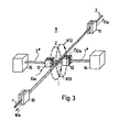
- connection 3 * shows an advantageous further embodiment of the invention as connection 3 * .
- central zone 4 is practically suppressed, namely that fiber bundles 1 and 2 essentially only face each other up to center Z in their original cross-section and then the first and second outlet zones 5 and 7 join them.
- the fiber beard 6 of the first fiber structure 1 is around the second fiber structure 2 wound and in the second outlet zone 7 of the fiber beard 8 of the second fiber structure 2 wound around the first fiber structure 1.
- connection 3 * it is essential that at least in a part of the outlet zones 5 and 7 individual fibers from the respective fiber strands 6 and 8 are non-positively connected to individual fibers emerging from the respective wound other fiber sliver.
- the non-positive connection is achieved to a sufficient extent by the dissolution of the fiber associations 1 and 2 into fiber beards 6 and 8 and by the winding which takes place under tension and shear motion.
- a connection 3 * according to FIG. 2 is characterized by special suppleness, flexibility, short length L * and a good, unobtrusive appearance, with sufficient strength being achieved.
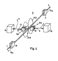
- FIG. 3 shows a schematic, perspective representation of the principle of a device for producing the connection and a first phase in the production of the connection.
- a connection 3 according to the invention is produced by a sequence of process steps. First, the fiber bundles 1 and 2 to be connected are guided against each other from the opposite direction over a small overlap in the area of a still virtual center Z of the intended connection 3 and then guided away from the other fiber bundle in a different direction and initially held in the course described .
- the parts of the two fiber bundles to be connected that are led away are then limited in length by separating their free ends, such that a fiber beard is formed on each part that is led away.
- the two parts that are led away are wound around the other fiber structure in the opposite direction of rotation or direction of rotation.
- the rotational movement around the respective other fiber structure is any taken away part of a movement relative to the other fiber bundle issued as a thrust movement in the direction of the overlap area p ung the fed fiber associations, such that the pushing movement is away directed to the first taken away part from the center Z and the thrust motion on the second part is also directed away from the center Z, but runs opposite to the first pushing movement.
- connection 3 in which the circulation of the parts taken away against the self-twist has been selected, will often result in an inconspicuous appearance compared to the normal fiber structure image.
- the device 9 has a first thread clamp 10 for receiving the first fiber structure 1 and a second thread clamp 11 for the second fiber structure 2.
- the first fiber structure 1 is guided from the first thread clamp 10 to a third thread clamp 12 adjacent to the virtual center Z and held under tension.
- the second fiber structure 2 coming from the opposite direction is also passed through a fourth thread clamp 13 and held under tension.
- the third thread clamp 12 is movably mounted in such a way that it can execute a rotary movement or a circular movement encircling the second fiber structure 2, as symbolically indicated by the circular path K12.
- the fourth thread clamp 13 is also movably mounted, in such a way that it can execute a rotary movement or circular movement encircling the first fiber structure 1, as symbolically indicated by the circular path K13.
- the circular paths K12 and K13 run in parallel planes, but are directed in opposite directions.
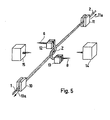
- the guided away part 1 * of the first fiber structure is picked up by a first thread dissolving device 14.
- the part 2 * of the second fiber structure 2 that is led away is received by a second thread dissolving device 15.
- the second thread clamp 12 can also be displaced in a direction 12a along the supplied second fiber structure 2.
- the third thread clamp 13 can also be displaced in a direction 13a along the supplied first fiber structure 1.
- the first thread clamp 10 and the second thread clamp 11 can also be mounted displaceably, preferably in the direction of the supplied fiber associations 1 or 2, but directed away from the center Z, that is to say in the directions 10a or 11a.
- the attachment to the fiber beard 6 or 8, preferably up to approximately the virtual center Z, are drawn.
- connection 3 or 3 * The principle of operation for forming a connection 3 or 3 * was explained above with reference to FIG. 3. Individual method steps are now explained in more detail with the aid of further figures.
- Thread opening devices are known. They can also be designed as vortex-forming suction nozzles.
- the thread dissolving devices 14 and 15 can also form a fiber beard by fraying and / or untwisting and / or by the action of frictional force.
- FIG. 5 shows how, after the formation of the whiskers 6 and 8 (see FIG. 4), the circumferential movement of the third fiber clamp 12 and the fourth thread clamp 13 in the region of the center Z, the winding of the two fiber bundles 1 and 2 after about half Circulation begins or arises.
- the clamping devices 12 or 13 can also have their clamping planes in a different direction from that shown in FIG. 3, for example as in FIG. 8.
- the pushing movement can also be generated automatically, in that the winding automatically comes to rest next to the winding, as is the case it happens when a wire is wound onto a cylinder and is known.
- the thrust movement can also be generated, for example, by corrugation of the friction surfaces in the clamping jaws and / or by smaller angular deviations of the part 1 * , 2 * of the fiber structure 1 or 2 that is carried away.
- the angle of FIGS. 6 to 8 shown in FIGS 90 ° is not mandatory, but freely selectable.
Landscapes
- Treatment Of Fiber Materials (AREA)
Applications Claiming Priority (2)
| Application Number | Priority Date | Filing Date | Title |
|---|---|---|---|
| CH5532/82 | 1982-09-20 | ||
| CH553282 | 1982-09-20 |
Publications (1)
| Publication Number | Publication Date |
|---|---|
| EP0103693A2 true EP0103693A2 (fr) | 1984-03-28 |
Family
ID=4295195
Family Applications (1)
| Application Number | Title | Priority Date | Filing Date |
|---|---|---|---|
| EP83106844A Withdrawn EP0103693A2 (fr) | 1982-09-20 | 1983-07-12 | Raccordement de fils textiles, procédé et dispositif de raccordement |
Country Status (2)
| Country | Link |
|---|---|
| EP (1) | EP0103693A2 (fr) |
| JP (1) | JPS5959972A (fr) |
Cited By (1)
| Publication number | Priority date | Publication date | Assignee | Title |
|---|---|---|---|---|
| EP0123329A1 (fr) * | 1983-03-28 | 1984-10-31 | Officine Savio S.p.A. | Procédé de raccordement pour fils textiles |
Families Citing this family (1)
| Publication number | Priority date | Publication date | Assignee | Title |
|---|---|---|---|---|
| JP4488384B1 (ja) * | 2009-10-30 | 2010-06-23 | 美也子 岡本 | 糸結び製造方法及びその装置 |
-
1983
- 1983-07-12 EP EP83106844A patent/EP0103693A2/fr not_active Withdrawn
- 1983-08-26 JP JP15512483A patent/JPS5959972A/ja active Pending
Cited By (1)
| Publication number | Priority date | Publication date | Assignee | Title |
|---|---|---|---|---|
| EP0123329A1 (fr) * | 1983-03-28 | 1984-10-31 | Officine Savio S.p.A. | Procédé de raccordement pour fils textiles |
Also Published As
| Publication number | Publication date |
|---|---|
| JPS5959972A (ja) | 1984-04-05 |
Similar Documents
| Publication | Publication Date | Title |
|---|---|---|
| EP1453751B1 (fr) | Procede et dispositif de liaison de plusieurs fils, en particulier d'extremites de fils | |
| DE2321354B2 (de) | Verfahren und Vorrichtung zur Herstellung von Mischgarnen | |
| DE3148940A1 (de) | Verfahren zum herstellen eines umwindegarnes, das umwindegarn und eine vorrichtung zum durchfuehren des verfahrens | |
| DE2746290A1 (de) | Verfahren zur wicklung von faserverstaerkten verbundkoerpern | |
| CH660723A5 (de) | Pneumatische garnspleisseinrichtung zum spleissen von gesponnenen garnen. | |
| DE3717921C2 (fr) | ||
| DE2942385C2 (de) | Verbindung von langgestreckten Faserverbänden, Verfahren zur Erzeugung einer solchen Verbindung und Vorrichtung zum Durchführen dieses Verfahrens | |
| EP0103693A2 (fr) | Raccordement de fils textiles, procédé et dispositif de raccordement | |
| DE3104472C2 (de) | Verfahren zur Verminderung abrupten Querschnittverlaufs bei einer durch Spleißen hergestellten Verbindung von Faserverbänden | |
| DE4038982C2 (de) | Verfahren und Vorrichtung zum Verbinden von Fasersträngen | |
| DE102013016628A1 (de) | Spinndüse zum Extrudieren von selbstkräuselnden Holfasern sowie selbstkräuselnde Hohlfasern und Verfahren zum Herstellen von selbstkräuselnden Hohlfasern | |
| DE3243410C2 (de) | Verfahren zur Herstellung einer Verbindung zwischen zwei Enden eines Zwirns | |
| DE1805352A1 (de) | Verfahren und Vorrichtung zum Verbinden von textilen Fadenstraengen und -baendern | |
| DE4240728C2 (de) | Verfahren zum knotenlosen Verbinden von Textilfäden bzw. Garnen mittels Druckluft und Vorrichtung zur Durchführung des Verfahrens | |
| DE3227401C2 (de) | Verfahren zum Spinnen eines Garnes aus zwei unterschiedlichen Stapelfaser-Komponenten | |
| DE69210587T2 (de) | Verfahren und vorrichtung zum verbinden von zwei fadenenden | |
| DE10024670B4 (de) | Verfahren zur Herstellung eines Garnes | |
| DE1444083C3 (de) | Schmelz gesponnenes, synthetisches, thermoplastisches, orientiertes und im wesentlichen verzwirnungsfreies Mehr fadengarn | |
| WO1985000393A1 (fr) | Procede de fabrication de fil | |
| DE3012929C2 (de) | Vorrichtung zum Herstellen eines aus mehreren Garnkomponenten bestehenden Effektfadens | |
| DE69103017T2 (de) | Verbesserte garntrennung beim start. | |
| DE2660058C2 (de) | Vorrichtung zum Spinnen von Fasern zu einem Faden | |
| AT215334B (de) | Verfahren zur Herstellung dünner Garne aus Kokosfasern od. dgl. | |
| DE3603713A1 (de) | Verfahren zur herstellung einer lichtwellenleiter enthaltenden bandleitung | |
| DE1435527C (de) | Verfahren zur Herstellung kräuselbarer Verbundfaden |
Legal Events
| Date | Code | Title | Description |
|---|---|---|---|
| PUAI | Public reference made under article 153(3) epc to a published international application that has entered the european phase |
Free format text: ORIGINAL CODE: 0009012 |
|
| 17P | Request for examination filed |
Effective date: 19830712 |
|
| AK | Designated contracting states |
Designated state(s): BE DE FR GB IT |
|
| STAA | Information on the status of an ep patent application or granted ep patent |
Free format text: STATUS: THE APPLICATION HAS BEEN WITHDRAWN |
|
| 18W | Application withdrawn |
Withdrawal date: 19841107 |
|
| R18W | Application withdrawn (corrected) |
Effective date: 19841107 |
|
| RIN1 | Information on inventor provided before grant (corrected) |
Inventor name: FELIX, ERNST |