EP0103750A2 - Instrument à écrire - Google Patents
Instrument à écrire Download PDFInfo
- Publication number
- EP0103750A2 EP0103750A2 EP83108108A EP83108108A EP0103750A2 EP 0103750 A2 EP0103750 A2 EP 0103750A2 EP 83108108 A EP83108108 A EP 83108108A EP 83108108 A EP83108108 A EP 83108108A EP 0103750 A2 EP0103750 A2 EP 0103750A2
- Authority
- EP
- European Patent Office
- Prior art keywords
- closure cap
- writing
- writing tip
- cap
- wedge
- Prior art date
- Legal status (The legal status is an assumption and is not a legal conclusion. Google has not performed a legal analysis and makes no representation as to the accuracy of the status listed.)
- Granted
Links
Images
Classifications
-
- B—PERFORMING OPERATIONS; TRANSPORTING
- B43—WRITING OR DRAWING IMPLEMENTS; BUREAU ACCESSORIES
- B43K—IMPLEMENTS FOR WRITING OR DRAWING
- B43K23/00—Holders or connectors for writing implements; Means for protecting the writing-points
- B43K23/08—Protecting means, e.g. caps
- B43K23/12—Protecting means, e.g. caps for pens
- B43K23/128—Protecting means, e.g. caps for pens with spring means
-
- B—PERFORMING OPERATIONS; TRANSPORTING
- B43—WRITING OR DRAWING IMPLEMENTS; BUREAU ACCESSORIES
- B43K—IMPLEMENTS FOR WRITING OR DRAWING
- B43K23/00—Holders or connectors for writing implements; Means for protecting the writing-points
- B43K23/08—Protecting means, e.g. caps
- B43K23/12—Protecting means, e.g. caps for pens
- B43K23/126—Protecting means, e.g. caps for pens with clips
Definitions
- the invention refers to a writing instrument with a removable closure cap sealingly sealing the writing tip, which has at least one substantially axially extending, elastically deformable finger on its insertion side, which engages with a recess in the barrel or in the writing tip when the closure cap is attached, whereby an annular shoulder of the writing instrument located in the sealing cap is in sealing engagement with a sealing shoulder of the sealing cap.
- Such an unlocking device is both complex to manufacture and prone to failure because it has parts that can be moved against spring pressure.
- a writing instrument of the type mentioned at the outset is designed in such a way that at least one cam surface is provided on the surface of the finger facing the recess when the closure cap is attached, which cam surface lies essentially in a plane of the circular chord of the circle forming the closure cap opening, which is caused by rotation of the attached closure cap can be brought into engagement with a correspondingly shaped wedge surface on the barrel or on the writing tip.
- At least two oppositely inclined cam surfaces are preferably provided on the finger Have the smallest radial distance from the longitudinal axis of the closure cap in the area of their cutting line, and the two cam surfaces can be guided between corresponding, oppositely inclined wedge surfaces.
- the existing plug connection between the closure cap and the writing tip in the writing device designed according to the invention can thus be released with the aid of the engagement of an inclined cam surface with a correspondingly inclined wedge surface, because this engagement and rotation of the attached closure cap with respect to the writing tip of the elastically deformable fingers of the closure cap radially outward is pivoted and so the projection having the cam surface is released from the recess in the barrel or in the pen body. As a result, the closure cap can then be removed from the writing tip.
- the closure cap can be loosened by rotating it in any direction with respect to the writing tip.
- oppositely inclined wedge surfaces can be provided on the shaft or on the writing tip over the entire circumference, so that even with a relatively small twist there is already an engagement of the cam surface and the wedge surface and thus the release of the closure cap allows pivoting of the arm radially outwards.
- the oppositely inclined wedge surfaces can be connected to one another at their end region closer to the front end of the writing tip, leaving the wedge surface tips free, so that the recess for the engagement of the finger is located behind this connection and the engagement takes place by means of a projection carrying the cam surfaces. Since the wedge surface tips protrude beyond the connection areas, the cam surfaces are lifted beyond the wedge surfaces when rotated accordingly, which enables the cap to be pulled off without resistance.
- the areas of the cam surfaces facing the insertion side of the closure cap can be used inclined radially inwards to the longitudinal axis and from the insertion side to the inner end, or the areas of the wedge surfaces facing the front end of the writing tip can be inclined radially outwards to the longitudinal axis and from the front end to the lower end.
- the arm is pushed radially outwards in every position when the closure cap is fitted on, and is thus moved into the area of the wedge surfaces. In this area, a corresponding rotation of the closure cap with respect to the writing tip then takes place automatically by engagement of the wedge surfaces with the cam surfaces, so that the desired engagement is achieved.
- closure cap is understood to mean both a conventional push-on cap and a quiver element, as is used, for example, in a writing instrument stand.
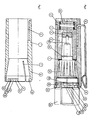
- the writing instrument partially shown is a tube pen with a writing tip 20 in the front End of a writing tube 22 is held '.
- a conventional ink compensation chamber not shown, is covered by a sleeve 21 which can be pulled off towards the writing tube 22 in order to expose the ink compensation chamber for cleaning.
- wedge surfaces are arranged on the circumference of the writing tip, of which only the wedge surfaces 23, 24, 27, 28 are designated. These wedge surfaces are flat, and the wedge surface 27 rises clockwise, for example, as seen from the writing tube 22, that is, its distance from the central axis of the writing tip 20 increases gradually until the edge 26 is reached at which the wedge surface 27 ends and the wedge surface 24 begins, which begins with the same inclination as the wedge surface 27 at the edge 26 and, viewed clockwise from the writing tube 22, decreases its distance from the central axis of the writing tip 20 until the beginning of the wedge surface 23 is reached, which then corresponds to the wedge surface 27 increases. It should be mentioned that all wedge surfaces have the same shape and dimensions.
- the end regions of the wedge surfaces on the left in FIG. 1, that is to say those end regions which are closer to the writing tube 22, are connected to one another by webs 25, 29, ie the web 25 connects the wedge surfaces 23 and 24 and the web 29 the wedge surfaces 27 and 28.
- the remaining wedge surfaces are. connected to each other in the same way by webs not designated.
- the height of the webs is less than the tips of the wedge surfaces, which result from the intersection of two adjacent wedge surfaces and one of which is designated by 26.
- the wedge surfaces and the webs are formed in one piece with the writing tip 20.
- the closure cap has a sleeve 1, preferably made of plastic, which has a groove 6 at its left end in the figures for receiving the fastening end of a clip 6 '.
- the clip is held in place by a cup-shaped insert 3 and a plug-in button 2.
- a cup-shaped insert 3 In the bottom area of the insert 3 there is an elastic seal 4 and on the end face of the insert 3 on the right in FIG. 1 an elastic ring seal 5 is provided.
- the ring seal 5 seals the annular space between the writing tip 20 and the sleeve 21, while the front end of the writing tube 22 is closed by the seal 40.
- the provided between the plug 2 and insert 3 spring 16 presses the Insert 3 and thus the seal 4 and the ring seal 5 against the writing tip.
- An elastically deformable arm 8 is formed in the sleeve 1 by axially extending incisions, of which the incision 7 can be seen in FIG. 2, while the second incision runs at the same height as the incision 7 in FIG. 2 and has the same depth.
- Cam surfaces are formed on the free end of the arm 8 and on the remaining wall of the sleeve 1 in the region of the insertion opening, that is to say at the level of the free end of the arm 8. These cam surfaces are flat and run at the same inclination as the wedge surfaces of the writing tip. For example, the cam surface 9 rises clockwise from the left end of the sleeve 1 in FIG. 1 and decreases its distance from the central axis of the sleeve 1 until the beginning of the.
- Cam surface 10 is reached, which has the same inclination from the central axis of the sleeve 1 enlarged. Accordingly, the cam surface 11 reduces its distance from the central axis of the sleeve 1 during the transition from the cam surface 10 to the cam surface 12 and the cam surface 12 runs in the same way as the cam surface 10.
- the cam surface 13 recognizable on the arm 8 is one of two formed on this arm Cam surfaces. It runs on the sleeve 1 from the sectional plane to the rear and reduces its distance from the central axis of the sleeve 1, while the cam surface, not shown, runs forward with a corresponding inclination from the sectional plane and reduces its distance from the central axis of the sleeve 1. The cam surfaces are therefore all in the chord planes of those circles which form the cylindrical opening area of the sleeve 1.
- cam surfaces 9-10 there are 8 cam surfaces on the arm, of which only the cam surface 13 can be seen.
- a further group of cam surfaces 9, 10, 11, 12 is provided in the opening area thereof.
- a corresponding group of cam surfaces can be offset by 120 in the opening area of the sleeve 1.
- the cam surfaces on the opening side of the sleeve 1 are chamfered, so that axially and radially inwardly extending surface areas 14 and 15 are formed from the opening side.
- these inclined surfaces 14, 15 and the corresponding inclined surfaces on the arm 8 either come into engagement with the ends of the wedge surfaces which project to the left in FIG. 1 or with the webs 25, 29.
- the inclined surfaces slide over the contact surfaces on the writing tip 20 and the arm 8 is pivoted radially outwards.
- the cam surfaces 9, 10, 11, 12, 13 can slide over the webs 20, 29 and reach the area of the wedge surfaces 23, 24, 27, 28, which are to the right of the webs 25, 29 in FIG.
- the closure cap and the writing tip 20 are rotated relative to one another.
- the cam surfaces of the sleeve 1 slide on the wedge surfaces of the writing tip 20 and the arm 8 is thereby pivoted radially outwards.
- This sliding of the cam surfaces along the Wedge surfaces must be continued until the radially innermost regions of the cam surfaces, that is to say for example the cutting edge of cam surface 9 and cam surface 10 (FIG. 2), are above the webs 25, 29.
- the cam surfaces or the projections forming them are moved radially further outward than the height of the webs 25 and 29.
- the closure cap is reduced due to the elasticity of the ring seal 5 and the seal 4 and the action of the spring 16 on the left (FIG. 1) and can be removed from the writing tip 20.
Landscapes
- Mechanical Pencils And Projecting And Retracting Systems Therefor, And Multi-System Writing Instruments (AREA)
- Pens And Brushes (AREA)
- Clips For Writing Implements (AREA)
- Aiming, Guidance, Guns With A Light Source, Armor, Camouflage, And Targets (AREA)
- Electrochromic Elements, Electrophoresis, Or Variable Reflection Or Absorption Elements (AREA)
- Surgical Instruments (AREA)
Priority Applications (1)
| Application Number | Priority Date | Filing Date | Title |
|---|---|---|---|
| AT83108108T ATE41121T1 (de) | 1982-09-17 | 1983-08-17 | Schreibgeraet. |
Applications Claiming Priority (2)
| Application Number | Priority Date | Filing Date | Title |
|---|---|---|---|
| DE3234514 | 1982-09-17 | ||
| DE3234514A DE3234514C2 (de) | 1982-09-17 | 1982-09-17 | Schreibgerät mit Verschlußkappe |
Publications (3)
| Publication Number | Publication Date |
|---|---|
| EP0103750A2 true EP0103750A2 (fr) | 1984-03-28 |
| EP0103750A3 EP0103750A3 (en) | 1986-08-13 |
| EP0103750B1 EP0103750B1 (fr) | 1989-03-08 |
Family
ID=6173489
Family Applications (1)
| Application Number | Title | Priority Date | Filing Date |
|---|---|---|---|
| EP83108108A Expired EP0103750B1 (fr) | 1982-09-17 | 1983-08-17 | Instrument à écrire |
Country Status (7)
| Country | Link |
|---|---|
| US (1) | US4558966A (fr) |
| EP (1) | EP0103750B1 (fr) |
| JP (1) | JPS5985763A (fr) |
| AT (1) | ATE41121T1 (fr) |
| BR (1) | BR8305044A (fr) |
| DE (1) | DE3234514C2 (fr) |
| MX (1) | MX153505A (fr) |
Cited By (1)
| Publication number | Priority date | Publication date | Assignee | Title |
|---|---|---|---|---|
| FR2624437A1 (fr) * | 1987-12-10 | 1989-06-16 | Staedtler J S Gmbh & Co | Instrument d'ecriture ou dessin |
Families Citing this family (18)
| Publication number | Priority date | Publication date | Assignee | Title |
|---|---|---|---|---|
| DE3640517A1 (de) * | 1986-11-27 | 1988-06-09 | Staedtler Fa J S | Von einem schreib- oder zeichengeraet abnehmbares huelsenfoermiges bauteil |
| US4917522A (en) * | 1988-05-17 | 1990-04-17 | Photofinish Cosmetics, Inc. | Manually-operated fluid dispenser and associated closure cap |
| DE3920773A1 (de) * | 1988-12-07 | 1990-06-13 | Pelikan Ag | Patronenfuellhalter |
| US5535487A (en) * | 1992-09-04 | 1996-07-16 | The Gillette Company | Clip attachment apparatus for a writing instrument |
| JP2572604Y2 (ja) * | 1992-09-04 | 1998-05-25 | 株式会社壽 | 筆記具のクリップ取付け機構 |
| US5353819A (en) * | 1993-04-19 | 1994-10-11 | Kahn Michael N | Lotion wand |
| DE4324593C1 (de) * | 1993-07-22 | 1994-08-18 | Pelikan Ag | Handschreibgerät mit abnehmbarer Kappe |
| JP2595554Y2 (ja) * | 1993-07-28 | 1999-05-31 | オート株式会社 | 筆記具用安全キャップ |
| US6095708A (en) * | 1998-09-17 | 2000-08-01 | Butaud; Gary V. | Refillable deodorant dispenser |
| USD416579S (en) | 1998-09-22 | 1999-11-16 | Parker Pen Products | Clip for a writing instrument |
| US6235005B1 (en) * | 1998-12-28 | 2001-05-22 | Ethicon, Inc. | Positive engagement-disengagement catheter sleeve |
| USD416580S (en) | 1999-03-25 | 1999-11-16 | Parker Pen Products | Clip for a writing instrument |
| US6186685B1 (en) * | 1999-04-05 | 2001-02-13 | The Gillette Company | Marking instrument housing |
| US6309127B1 (en) | 1999-05-07 | 2001-10-30 | Berol Corporation | Caps for writing instruments |
| US6626600B1 (en) | 2000-09-13 | 2003-09-30 | Binney & Smith Inc. | Writing instrument |
| US6464420B2 (en) | 2001-03-29 | 2002-10-15 | Chartpak, Inc. | Liquid ink writing pen with visible tip |
| US7168105B2 (en) * | 2004-01-20 | 2007-01-30 | Adelman Gregory M | Convertible multi-use writing instrument |
| USD705866S1 (en) | 2013-01-05 | 2014-05-27 | Nite Ize, Inc. | Pen holder including a stylus |
Family Cites Families (20)
| Publication number | Priority date | Publication date | Assignee | Title |
|---|---|---|---|---|
| US1239971A (en) * | 1916-02-25 | 1917-09-11 | William J Ruff | Fountain-pen. |
| US1838543A (en) * | 1928-05-17 | 1931-12-29 | Aaron A Goldstein | Fountain pen and the like |
| US2102044A (en) * | 1934-03-31 | 1937-12-14 | Chilton Pen Company Inc | Fountain pen and the like |
| US2192644A (en) * | 1938-02-21 | 1940-03-05 | May Wallace E La | Fastening for fountain pen caps |
| FR992128A (fr) * | 1944-05-13 | 1951-10-15 | Jif | Porte-plume à capuchon |
| US2396771A (en) * | 1944-08-03 | 1946-03-19 | Sr Dara H Brinson | Fountain pen |
| US2453491A (en) * | 1944-11-29 | 1948-11-09 | Carl J Cardin | Fountain pen |
| GB631195A (en) * | 1946-01-25 | 1949-10-28 | Jesus Plaza Rodriguez | Improvements in and relating to the construction of safety-caps for fountain pens |
| US2436763A (en) * | 1946-03-23 | 1948-02-24 | Russell T Wing | Writing instrument |
| FR942385A (fr) * | 1947-02-19 | 1949-02-07 | Dispositif d'accouplement automatique à verrouillage de sûreté | |
| DE945818C (de) * | 1952-03-18 | 1956-07-19 | Hans Heinrich Huebner | Aufsteckschutzkappe fuer Fuellfederhalter |
| US3184782A (en) * | 1963-07-30 | 1965-05-25 | Monsanto Co | Dispensing device |
| US3252446A (en) * | 1964-08-13 | 1966-05-24 | Carter S Ink Co | Friction closure |
| GB1207268A (en) * | 1967-09-06 | 1970-09-30 | Montblanc Simplo Gmbh | Improvements relating to liquid ink writing instruments |
| US3802788A (en) * | 1972-07-13 | 1974-04-09 | Koh I Noor Rapidograph | Stylographic pen cap |
| DE3001914C2 (de) * | 1980-01-19 | 1982-10-07 | Fa. J.S. Staedtler, 8500 Nürnberg | Verschlußkappe für Schreibgeräte |
| DE3010862A1 (de) * | 1980-03-21 | 1981-10-01 | Otto 6900 Heidelberg Mutschler | Aufnahme- und haltebox fuer tuschefueller |
| US4341482A (en) * | 1980-09-22 | 1982-07-27 | Sanford Research Company | Housing assembly for fluid marking device |
| JPS5812486U (ja) * | 1981-07-16 | 1983-01-26 | 株式会社サクラクレパス | 筆記具 |
| JPS58107881U (ja) * | 1982-01-18 | 1983-07-22 | 三菱鉛筆株式会社 | 筆記具のキヤツプ |
-
1982
- 1982-09-17 DE DE3234514A patent/DE3234514C2/de not_active Expired
-
1983
- 1983-08-17 EP EP83108108A patent/EP0103750B1/fr not_active Expired
- 1983-08-17 AT AT83108108T patent/ATE41121T1/de not_active IP Right Cessation
- 1983-09-09 US US06/530,819 patent/US4558966A/en not_active Expired - Fee Related
- 1983-09-16 BR BR8305044A patent/BR8305044A/pt not_active IP Right Cessation
- 1983-09-17 JP JP58170626A patent/JPS5985763A/ja active Granted
- 1983-09-19 MX MX198745A patent/MX153505A/es unknown
Cited By (1)
| Publication number | Priority date | Publication date | Assignee | Title |
|---|---|---|---|---|
| FR2624437A1 (fr) * | 1987-12-10 | 1989-06-16 | Staedtler J S Gmbh & Co | Instrument d'ecriture ou dessin |
Also Published As
| Publication number | Publication date |
|---|---|
| DE3234514A1 (de) | 1984-03-22 |
| DE3234514C2 (de) | 1985-03-07 |
| JPH0352358B2 (fr) | 1991-08-09 |
| BR8305044A (pt) | 1984-05-08 |
| ATE41121T1 (de) | 1989-03-15 |
| JPS5985763A (ja) | 1984-05-17 |
| EP0103750B1 (fr) | 1989-03-08 |
| EP0103750A3 (en) | 1986-08-13 |
| US4558966A (en) | 1985-12-17 |
| MX153505A (es) | 1986-11-07 |
Similar Documents
| Publication | Publication Date | Title |
|---|---|---|
| DE3234514C2 (de) | Schreibgerät mit Verschlußkappe | |
| EP0665402B1 (fr) | Connecteur à fiche pour systèmes de conduites sous pression | |
| DE2413748A1 (de) | Anschluss fuer druckmittelleitungen | |
| EP0055859A2 (fr) | Dispositif de prélèvement sanguin | |
| EP1626463A2 (fr) | Connecteur à fiche | |
| DE2733385A1 (de) | Injektionsspritze | |
| DE2547411C3 (fr) | ||
| EP0374135A2 (fr) | Dispositif de connexion enfichable avec verrouillage de torsion | |
| DE3125441C2 (de) | Füllminenstift mit automatischem Minenvorschub und Nachschub der Folgemine | |
| DE3342141C2 (de) | Schreibgerät | |
| EP0220487B1 (fr) | Instrument à écrire | |
| DE2627397C3 (de) | Schnellkupplung zum Anschluß von Rohr- oder Schlauchleitungen | |
| DE2260065A1 (de) | Fuellminenstift mit verschiebbarer mine | |
| EP0795423B1 (fr) | Stylo à bille actionné par pression | |
| DE2732518A1 (de) | Schreibgeraet | |
| EP0185802A1 (fr) | Dispositif de raccord pour conduits à pression avec bague de support imperdable | |
| DE4308526B4 (de) | Steckkupplung für Rohr- und/oder Schlauchleitungen | |
| DE3121873C2 (fr) | ||
| EP1006307B1 (fr) | Raccord enfichable | |
| DE2604325C3 (de) | Wischvorrichtung für Scheiben von Kraftfahrzeugen | |
| DE3516093C2 (fr) | ||
| DE2717908C3 (de) | Schlauch- und/oder Rohrkupplung | |
| EP0144518B1 (fr) | Stylographe | |
| DE2654059C2 (de) | Ringgedichtete Rohrverbindung mit Dichtungsring | |
| WO2021209351A1 (fr) | Raccord à vis pour canalisations ou tuyaux |
Legal Events
| Date | Code | Title | Description |
|---|---|---|---|
| PUAI | Public reference made under article 153(3) epc to a published international application that has entered the european phase |
Free format text: ORIGINAL CODE: 0009012 |
|
| 17P | Request for examination filed |
Effective date: 19830817 |
|
| AK | Designated contracting states |
Designated state(s): AT BE CH FR GB IT LI LU NL SE |
|
| PUAL | Search report despatched |
Free format text: ORIGINAL CODE: 0009013 |
|
| AK | Designated contracting states |
Kind code of ref document: A3 Designated state(s): AT BE CH FR GB IT LI LU NL SE |
|
| 17Q | First examination report despatched |
Effective date: 19880121 |
|
| GRAA | (expected) grant |
Free format text: ORIGINAL CODE: 0009210 |
|
| AK | Designated contracting states |
Kind code of ref document: B1 Designated state(s): AT BE CH FR GB IT LI LU NL SE |
|
| REF | Corresponds to: |
Ref document number: 41121 Country of ref document: AT Date of ref document: 19890315 Kind code of ref document: T |
|
| ITF | It: translation for a ep patent filed | ||
| ET | Fr: translation filed | ||
| GBT | Gb: translation of ep patent filed (gb section 77(6)(a)/1977) | ||
| PLBE | No opposition filed within time limit |
Free format text: ORIGINAL CODE: 0009261 |
|
| STAA | Information on the status of an ep patent application or granted ep patent |
Free format text: STATUS: NO OPPOSITION FILED WITHIN TIME LIMIT |
|
| 26N | No opposition filed | ||
| ITTA | It: last paid annual fee | ||
| PGFP | Annual fee paid to national office [announced via postgrant information from national office to epo] |
Ref country code: SE Payment date: 19920708 Year of fee payment: 10 |
|
| PGFP | Annual fee paid to national office [announced via postgrant information from national office to epo] |
Ref country code: AT Payment date: 19920716 Year of fee payment: 10 |
|
| PGFP | Annual fee paid to national office [announced via postgrant information from national office to epo] |
Ref country code: LU Payment date: 19920805 Year of fee payment: 10 |
|
| PGFP | Annual fee paid to national office [announced via postgrant information from national office to epo] |
Ref country code: GB Payment date: 19920807 Year of fee payment: 10 |
|
| PGFP | Annual fee paid to national office [announced via postgrant information from national office to epo] |
Ref country code: FR Payment date: 19920827 Year of fee payment: 10 |
|
| PGFP | Annual fee paid to national office [announced via postgrant information from national office to epo] |
Ref country code: NL Payment date: 19920831 Year of fee payment: 10 |
|
| EPTA | Lu: last paid annual fee | ||
| REG | Reference to a national code |
Ref country code: CH Ref legal event code: PFA Free format text: ROTRING INTERNATIONAL GMBH & CO. KG |
|
| PGFP | Annual fee paid to national office [announced via postgrant information from national office to epo] |
Ref country code: BE Payment date: 19930727 Year of fee payment: 11 |
|
| PG25 | Lapsed in a contracting state [announced via postgrant information from national office to epo] |
Ref country code: LU Free format text: LAPSE BECAUSE OF NON-PAYMENT OF DUE FEES Effective date: 19930817 Ref country code: GB Effective date: 19930817 Ref country code: AT Effective date: 19930817 |
|
| PG25 | Lapsed in a contracting state [announced via postgrant information from national office to epo] |
Ref country code: SE Effective date: 19930818 |
|
| REG | Reference to a national code |
Ref country code: FR Ref legal event code: CD |
|
| PGFP | Annual fee paid to national office [announced via postgrant information from national office to epo] |
Ref country code: CH Payment date: 19930913 Year of fee payment: 11 |
|
| ITPR | It: changes in ownership of a european patent |
Owner name: CAMBIO RAGIONE SOCIALE;ROTRING INTERNATIONAL GMBH |
|
| NLS | Nl: assignments of ep-patents |
Owner name: ROTRING INTERNATIONAL GMBH & CO KG. TE HAMBURG, BO |
|
| PG25 | Lapsed in a contracting state [announced via postgrant information from national office to epo] |
Ref country code: NL Effective date: 19940301 |
|
| GBPC | Gb: european patent ceased through non-payment of renewal fee |
Effective date: 19930817 |
|
| NLV4 | Nl: lapsed or anulled due to non-payment of the annual fee | ||
| PG25 | Lapsed in a contracting state [announced via postgrant information from national office to epo] |
Ref country code: FR Effective date: 19940429 |
|
| REG | Reference to a national code |
Ref country code: FR Ref legal event code: ST |
|
| PG25 | Lapsed in a contracting state [announced via postgrant information from national office to epo] |
Ref country code: LI Effective date: 19940831 Ref country code: CH Effective date: 19940831 Ref country code: BE Effective date: 19940831 |
|
| EUG | Se: european patent has lapsed |
Ref document number: 83108108.8 Effective date: 19940310 |
|
| BERE | Be: lapsed |
Owner name: ROTRING INTERNATIONAL G.M.B.H. & CO. K.G. Effective date: 19940831 |
|
| REG | Reference to a national code |
Ref country code: CH Ref legal event code: PL |