EP0103758A2 - Méthode pour tester et vérifier la qualité de l'isolation à la terre pour un disjoncteur pendant l'interruption d'un courant de charge - Google Patents
Méthode pour tester et vérifier la qualité de l'isolation à la terre pour un disjoncteur pendant l'interruption d'un courant de charge Download PDFInfo
- Publication number
- EP0103758A2 EP0103758A2 EP83108179A EP83108179A EP0103758A2 EP 0103758 A2 EP0103758 A2 EP 0103758A2 EP 83108179 A EP83108179 A EP 83108179A EP 83108179 A EP83108179 A EP 83108179A EP 0103758 A2 EP0103758 A2 EP 0103758A2
- Authority
- EP
- European Patent Office
- Prior art keywords
- voltage
- disconnecting switch
- power supply
- test method
- insulation
- Prior art date
- Legal status (The legal status is an assumption and is not a legal conclusion. Google has not performed a legal analysis and makes no representation as to the accuracy of the status listed.)
- Granted
Links
Images


Classifications
-
- G—PHYSICS
- G01—MEASURING; TESTING
- G01R—MEASURING ELECTRIC VARIABLES; MEASURING MAGNETIC VARIABLES
- G01R3/00—Apparatus or processes specially adapted for the manufacture or maintenance of measuring instruments, e.g. of probe tips
-
- H—ELECTRICITY
- H01—ELECTRIC ELEMENTS
- H01H—ELECTRIC SWITCHES; RELAYS; SELECTORS; EMERGENCY PROTECTIVE DEVICES
- H01H33/00—High-tension or heavy-current switches with arc-extinguishing or arc-preventing means
- H01H33/02—Details
- H01H33/26—Means for detecting the presence of an arc or other discharge
-
- G—PHYSICS
- G01—MEASURING; TESTING
- G01R—MEASURING ELECTRIC VARIABLES; MEASURING MAGNETIC VARIABLES
- G01R31/00—Arrangements for testing electric properties; Arrangements for locating electric faults; Arrangements for electrical testing characterised by what is being tested not provided for elsewhere
- G01R31/327—Testing of circuit interrupters, switches or circuit-breakers
- G01R31/333—Testing of the switching capacity of high-voltage circuit-breakers ; Testing of breaking capacity or related variables, e.g. post arc current or transient recovery voltage
- G01R31/3333—Apparatus, systems or circuits therefor
Definitions
- the present invention relates to a method of verifying a performance for insulation to ground of a gas insulated disconnecting switch of the tank type when breaking a charging current.
- a disconnection test of a charging current of the gas insulated disconnecting switch is generally performed by means of a circuit which is approximately equivalent to the actual gas insulated disconnecting switch.
- Fig. 1 shows an example of such an equivalent circuit.
- An AC power supply 2 is connected through a bus bar 4 to one terminal of a disconnecting switch 6 and a circuit breaker 10 is coupled through a bus bar 8 to the other.
- a power feeding system (not shown) is further connected through the bus bar 12 to the other end of the circuit breaker 10, thereby constructing the circuit.
- an electrostatic capacity C i is also provided between the bus bar 8 and the ground.
- Fig. 2 shows transitions of a voltage V s on the power supply side and a voltage V l on the load side of the disconnecting switch.6 when breaking the charging current to the capacity C l by opening the disconnecting switch 6.
- the broken line shows the voltage V s on the power supply side and the solid line indicates the voltage V t on the load side.
- a surge voltage 16 occurs as shown in Fig. 2.
- the tests for the disconnecting switch are carried out to examine properties of insulation to ground for a predetermined gap length, interelectrode voltage and surge voltage.
- bushings 24 and 26 are arranged at both ends of the disconnecting switch 6, one end of the disconnecting switch 6 is connected through the bushing 24 to a power supply 20 and a capacitor 22 and the other end is connected through the bushing 26 to another power supply 36 and a capacitor 34, thereby carrying out the test using a circuit with such a construction.
- the power supply 36 is a DC voltage generator to simulate the load side voltage V l
- the power supply 20 is an impulse voltage generator or a half-wave AC voltage generator, etc. to simulate the power supply voltage V s having a polarity opposite to that of the power supply 36.
- Reference numerals 28 and 30 indicate voltage dividers to detect, divide and fetch the power supply voltage V s and load voltage V l , respectively. Outputs of the voltage dividers 28 and 30 are applied to a display unit, for example, oscilloscope 32, thereby indicating the waveforms of the power supply voltage V s and load voltage V l .
- an interelectrode distance of the disconnecting switch is first set into a length which is equal to the maximum arc length when breaking a charging current. Then, a DC voltage in response to a peak value of an AC output of the power supply 20 is applied from the power supply 36 to one contact of the disconnecting switch. Thereafter, a threshold voltage which corresponds to the waveform of 1/4 cycle of an AC voltage having a polarity opposite to that of the DC voltage of the power supply 36 is applied from the power supply 20 to the other contact of the disconnecting switch. In this way, the state between the times t 10 and t 12 of Fig. 2 is simulated in the disconnecting switch of Fig. 3 to carry out the restriking.
- the severest restriking arc condition for the disconnecting switch is simulated, and the insulation to ground at a surge voltage to be caused at this time is verified. According to this method, it is possible to perform the verification test sufficiently by selecting only the severest condition.
- the overall test facility of large scale is required due to the points such that two high-voltage power supplies are needed and that two bushings for high voltage are also necessary, or the like.
- a further larger scale test facility is required for UHV which is being developed recently, resulting in a great amount of test expenditure.
- the present inventors have confirmed by experiments that when a discharge time constant of a gas-insulated bus bar is enough large, once the gas-insulated bus bar has been charged due to an interelectrode discharge of the disconnecting switch, a charging voltage of the gas bus bar is maintained to be substantially constant for a long period of time.
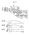
- FIG. 4 there is shown a circuit diagram of a typical embodiment of a gas-insulated disconnecting switch to carry out a test for insulation to ground according to the present invention.
- parts and elements that have the same functions as those shown in Figs. 1 and 3 are designated by the;same reference numerals.
- One electrode i.e. a fixed electrode 64 of the disconnecting switch 6 enclosed in a tank, e.g. a grounded tank is connected to a central conductor 56 of a gas bus bar 54 which forms a load.
- An electrostatic capacity C t is formed between the central conductor 56 of the gas bus bar 54 and a high-voltage conductor 58.
- the central conductor 56 is insulated and supported by an insulating spacer 52.
- the other electrode, i.e. a movable electrode 62 of the disconnecting switch 6 is connected to a central conductor 55.
- the central conductor 55 is connected through the bushing 24 and a lead wire 50 to a power supply 40.
- the central conductor 55 is supported by an insulating spacer 53.
- the power supply side voltage V and load side voltage V l of the disconnecting switch 6 are detected and divided by the voltage dividers 28 and 30, respectively, and then applied to a waveform display unit, for instance, an oscilloscope 32.
- the power supply 40 is a well-known power supply comprising: a power supply main body 42 having an equivalent electrostatic capacity C s ; an AC power supply 44; a voltage regulator 45 for regulating an output voltage of the AC power supply 44; a rectifier 46 for rectifying an output of the voltage regulator 45; a polarity change-over switch 47 for selectively switching a polarity of an output voltage of the rectifier 46; and a starter 48.
- the output of the rectifier is accumulated in the capacity C of the power supply main body.
- a trigger signal is applied from the starter 48, the charges accumulated in the capacity C s are discharged, so that a pulse-like high voltage as shown in Fig. 5A is applied through the bushing 24 to the movable electrode of the disconnecting switch 6.
- An output voltage of the power supply 40 can be regulated by the voltage regulator 45.
- a value of the capacity C is set into a value which is at least one digit larger than that of C i with respect to a relation between the electrostatic capacity C l of the load side gas bus bar and the equivalent electrostatic capacity C s on the power supply side.
- the movable electrode 62 can be manually moved by a driving apparatus 66, an example of which is illustrated in Fig. 6.
- a driving apparatus similar to that of Fig. 6 is shown, for example, in Fig. 2 in USP. No. 4263491.
- F ig. 6 is a detailed cross sectional view showing the disconnecting switch 6 and its driving apparatus 66 of Fig. 4.
- the disconnecting switch 6 includes the movable electrode 62 and fixed electrode 64 which are disposed in the high-voltage conductor 58 of the grounded tank, and shields 68 and 70 for lightening the electric field which are arranged around the electrodes 62 and 64.
- the movable electrode 62 is slidably supported to the inside of a conductive cylindrical member 72 fixed to the end portion of the central conductor 55.
- the central conductor 55 is supported by the insulating spacer 53.
- the driving apparatus for sliding the movable electrode 62 will be now described.
- the end portion of the movable electrode engages one end of a link member 76 through an insulating operating rod 74.
- the link member 76 is rotatable around a fulcrum 78, and the other end of the link member is come into link engagement with one end of an operating rod 80.
- the other end of the operating rod 80 is L-character shaped and a female screw portion 82 is formed therein.
- a needle 90 is attached to the edge of the rod 80.
- One end of the female screw portion 82 is rotatably supported to the high-voltage conductor 58 and the other end is adapted to threadably engage a male screw rod 84 coupled to a handle 86.
- a scale rod 88 is graduated at regular intervals for a distance L between the movable electrode 62 and the fixed electrode 64. This scale is determined by preliminarily obtaining a relation between a travelling amount L' of the needle 90 in association with the movement of the operating rod 80 and the distance L between the movable and fixed electrodes.
- the operating rod 80 moves in the direction indicated by an arrow 92.
- the operating rod 74 and, accordingly, the movable electrode 62 moves in the direction indicated by an arrow 94.
- the distance L between the electrodes at this time is a value pointed by the needle 90.
- the interelectrode distance L can be set into any values by the operation of the handle 86.
- a disconnecting switch which is commercially available, it is generally further provided with such an apparatus as to enable a remote controlling operation of the interelectrode distance using a motor or an air pressure in addition to the driving apparatus 66.
- the interelectrode distance L of the disconnecting switch 6 is set to a certain value by means of the driving apparatus 66. Then, a pulse-like voltage as shown in Fig. 5A is applied at time t 0 from the power supply 40 to the disconnecting switch 6.
- a pulse-like voltage as shown in Fig. 5A is applied at time t 0 from the power supply 40 to the disconnecting switch 6.
- the power voltage reaches a predetermined value to be determined on the basis of the interelectrode distance L at time t l
- the discharge occurs across the electrodes, so that charges are accumulated in the gas bus bar on the load side.
- the power supply side voltage V and load side voltage V l show the waveforms as shown in Figs. 5B and 5C. That is to say, the discharge is done across the electrodes at time t 1 and the DC voltage V l as shown in Fig.
- a discharge time constant of this residual voltage (i.e. the trapped charged voltage) is determined due to electrostatic capacity C l of the load side bus bar 56 and insulation resistance of the insulating spacer 52 which insulation- supports the high-voltage conductor 58 or the like.
- the above-mentioned discharge time constant is in the order of few hours to few days, because the insulation resistances of a spacer and the like that will be generally used in a gas-insulated apparatus are extremely higher than that of a spacer that will be used in the atmosphere. That is to say, a capacity of the insulating spacer in the gas-insulated apparatus is large, while inductance and resistance components are small, so that the residual voltage can be held without being attenuated.
- a performance for insulation to ground when breaking a charging current of such a disconnecting switch is determined by a performance against a restriking arc surge that will be caused at the location of the movable electrode which is the maximum arc distance.
- the restriking arc surge becomes highest at the time of restriking arc, as described previously, in the case where an AC peak value voltage of a positive polarity and a peak value voltage of a negative polarity are applied across the electrodes. Therefore, to carry out verification of a performance on insulation to ground, a distance between the electrodes of the disconnecting switch is first set into a predetermined value and a DC voltage is trapped on the load side according to the above-mentioned procedures.
- the interelectrode distance is increased to a predetermined length and a voltage having the same level as and the polarity opposite to the residual voltage is applied from the power supply side, thereby causing the discharge across the electrodes, and then the insulation to ground at that time is verified.
- a pulse-like voltage as shown in Fig. 5A is applied from the power supply side by setting the interelectrode distance L to a predetermined length.
- a relation between the interelectrode distance L and the flashover voltage V is preliminarily obtained, thereby determining the interelectrode distance L and the flashover voltage V from this relation.
- Fig. 7 shows a characteristic in the system of the class of 300 KV.
- a predetermined DC voltage is trapped on the load side, thereafter the interelectrode distance is increased to an interelectrode distance which is equal to the maximum arc length or the like. Then the polarity of the power supply 40 is changed by the polarity change-over switch 47 so that it is opposite to the polarity of the DC voltage that has been already trapped, and then a predetermined voltage which has been determined by the voltage regulator 45 is applied.
- Fig. 8 is a waveform diagram of the power supply side and load side voltages V s and V l in the system of the 300 KV class.
- the load side voltage V l is the voltage trapped in the electrostatic capacity C l of the load side bus bar due to the interelectrode discharge, and it is about -600 KV (-1 pu).
- a pulse-like voltage V s of a negative polarity is applied at a peak value of 600 KV (1 pu) at time t 3 .
- the voltage V s reaches a peak level (600 KV, i.e. a flashover voltage) at time t 41 the discharge occurs across the electrodes and a surge voltage V m is caused.
- the surge voltage is about 2.5 pu.
- the time period between t 3 and t 4 is about 200 - 500 ⁇ s.
- This situation is a completely simulated form of the final restriking arc (at time period of t 10 - t 12 ) in Fig. 2.
- V m surge voltage
- a leading waveform time period: 5 ms
- the insulation-to-ground verification can be sufficiently carried out even if a high-frequency pulse waveform (time period: 1 - 2 ⁇ s) may be used.
- the test is possible with single power supply and one bushing, and therefore, the verification test similar to a conventional one can be carried out by means of a testing apparatus of a small scale.
- an interelectrode voltage that is needed for a discharge in the case where the movable electrode is negative polarity and the fixed electrode is positive polarity, is lower than that in the case where the movable electrode is positive polarity and the fixed electrode is negative polarity.
- V shown in Fig. 5A after a power voltage V shown in Fig. 5A has been applied for allowing a voltage shown in Fig. 5C to be trapped in the load, when the power voltage V reduces and becomes V nl the interelectrode electric potential difference becomes V 0 -V n , so that the reverse flashover occurs.
- the first discharge is performed with the polarity at which the discharge due to a reverse flashover and dark current is hard to occur, that is to say, a negative power voltage having a peak value V 0 is applied to the electrode of.the power supply side, thereby trapping a DC voltage of negative polarity on the load side.
- a potential of the movable electrode is higher than that of the fixed electrode, so that the discharge will not occur until the interelectrode potential difference becomes a value higher than V O .
- a voltage of the opposite polarity (+ polarity) is applied to the movable electrode to perform the second discharge.
- the interelectrode voltage which is necessary for the first discharge i.e. the discharge from the movable electrode to fixed electrode to be lower than the voltage that is needed for the discharge (reverse flashover or the like) from the fixed electrode to movable electrode due to the residual voltage.
- the reverse flashover is difficult to occur.
- the interelectrode distances in the first and second discharges may be equal, or the interelectrode distance in thd second discharge may be longer than that in the first one.
- Fig. 9 is a cross sectional view of the disconnecting switch showing another embodiment of a test method of the present invention.
- the discharge due to the above-mentioned reverse flashover and dark current is prevented.
- a window 98 is provided at the side surface of the high-voltage conductor 58 of the grounded tank, and a beam, such as ultraviolet rays,-radioactive rays and laser beam, generated from a radiating apparatus (mercury lamp, laser generator, etc.) 96 can be irradiated through the window 98 into the region between the electrodes 62 and 64.
- Fig. 10 shows characteristics of the interelectrode discharge with respect to presence and absence of irradiation of the beam into the region between the electrodes.
- the solid line I and broken line II indicate the relations between the interelectrode distance L and the flashover voltage FOV in the case where no beam is radiated and in the case where a light beam is radiated, respectively.
- the interelectrode distance is set to L 1 (50 mm)
- V i 670 KV
- a power voltage shown in Fig. 11A is applied to the movable electrode.
- the radiation of a light beam from the radiating apparatus 96 to the head portion of the movable electrode 62 causes the flashover voltage to reduce from V 0 to V i , so that the discharge is started at time t 1 (Fig. 11B).
- a voltage V i is trapped on the load side.
- a light beam is radiated to only the movable electrode and no beam is radiated to the fixed electrode, so that a voltage that is required for the discharge from the fixed electrode to movable electrode is V 0 and consequently no reverse flashover will be caused.
- both flashover voltage for discharging from the movable electrode to fixed electrode and flashover voltage for discharging from the fixed electrode to movable electrode reduce from V 0 to V i .
- a light beam is radiated from the radiating apparatus 96 only in the period of time when the wave front portion of the power voltage V s (corresponding to time t 0 - t 1 of Fig. 11A) exists.
- the discharge occurs from the movable electrode to fixed electrode at time t 1 , so that a voltage V i is trapped in the load.
- the beam radiation is now finished and the flashover voltage for discharging from the fixed electrode to movable electrode increases to V 0 , so that no reverse flashover will be caused.
- the radiating apparatus 96 radiates a light beam for only a predetermined period of time t 0 - t 1 in response to a trigger signal from the starter 48 synchronously with the time when the power voltage V s is applied.
- the reverse flashover will be caused when the power voltage V becomes almost zero before ionized gas reacts completely.
- Fig. 12 shows another embodiment of the test method by which the discharge due to reverse flashover and dark current is prevented.
- the inside of the head portion of the movable electrode 62 shown in Fig. 6 is hollowed out and a conductive trigger electrode 102 supported by an insulated supporting member 100 is attached into the hole.
- the flashover voltage for discharging from the movable electrode to fixed electrode reduces by about 10% due to this discharge, causing the interelectrode discharge at a lower level (e.g. V i at time t 1 of Fig. 11A) of the power voltage V s , so that the voltage V i is trapped in the load.
- V i the interelectrode discharge
- a DC electric field is caused between the trigger electrode and the movable electrode, so that a potential difference therebetween will disappear. Therefore, upon starting the interelectrode discharge, the discharge between the trigger electrode and the movable electrode disappears, this causes the flashover voltage between electrodes to increase to V O .
- the flashover voltage for discharging from the fixed electrode to movable electrode becomes V 0 , thereby preventing the reverse flashover.
- a power voltage of -V i (-1 pu) is applied to the disconnecting switch when carrying out the second discharge, thereby performing the test for insulation to ground.
- the interelectrode distances at the first and second discharges may be identical, or the distance upon the second discharge may be larger than that of the first one.
- the interelectrode distance can be set to be long by way of radiating a light beam at the time of the first discharge or by providing the movable and trigger electrodes as described above. Therefore, it is possible to form a stable residual voltage without any fluctuation.
- the movable electrode was used on the power supply side, it may be possible to use the movable electrode on the load side and the fixed electrode on the power supply side.
- the trigger electrode is provided in the movable electrode in the embodiment of Fig. 12, it may be provided in the fixed electrode.
- the discharge due to reverse flashover or dark current after a DC voltage has been trapped can be easily prevented and the DC residual voltage can be easily controlled, this results in an improvement in efficiency of the test.
- the verification for insulation to ground when breaking a charging current of the disconnecting switch can be carried out with a small-scale facility using single power supply and only one bushing; therefore, its application effect will be larger against the disconnecting switch with a higher rated voltage.
- the present invention can advantageously provide a large effect as a test method using one bushing.
Landscapes
- Physics & Mathematics (AREA)
- General Physics & Mathematics (AREA)
- Testing Relating To Insulation (AREA)
- Gas-Insulated Switchgears (AREA)
- Testing Electric Properties And Detecting Electric Faults (AREA)
Applications Claiming Priority (2)
| Application Number | Priority Date | Filing Date | Title |
|---|---|---|---|
| JP57143417A JPS5934170A (ja) | 1982-08-20 | 1982-08-20 | 断路器の充電電流しや断時対地絶縁検証試験法 |
| JP143417/82 | 1982-08-20 |
Publications (3)
| Publication Number | Publication Date |
|---|---|
| EP0103758A2 true EP0103758A2 (fr) | 1984-03-28 |
| EP0103758A3 EP0103758A3 (en) | 1985-08-28 |
| EP0103758B1 EP0103758B1 (fr) | 1989-05-31 |
Family
ID=15338268
Family Applications (1)
| Application Number | Title | Priority Date | Filing Date |
|---|---|---|---|
| EP83108179A Expired EP0103758B1 (fr) | 1982-08-20 | 1983-08-18 | Méthode pour tester et vérifier la qualité de l'isolation à la terre pour un disjoncteur pendant l'interruption d'un courant de charge |
Country Status (9)
| Country | Link |
|---|---|
| US (1) | US4549132A (fr) |
| EP (1) | EP0103758B1 (fr) |
| JP (1) | JPS5934170A (fr) |
| KR (1) | KR890000692B1 (fr) |
| AU (1) | AU544370B2 (fr) |
| CA (1) | CA1205860A (fr) |
| DE (1) | DE3379980D1 (fr) |
| IN (1) | IN160109B (fr) |
| ZA (1) | ZA836141B (fr) |
Cited By (1)
| Publication number | Priority date | Publication date | Assignee | Title |
|---|---|---|---|---|
| DE19648643A1 (de) * | 1996-11-25 | 1998-05-28 | Asea Brown Boveri | Metallgekapselte gasisolierte Schaltanlage |
Families Citing this family (12)
| Publication number | Priority date | Publication date | Assignee | Title |
|---|---|---|---|---|
| JPS6319570A (ja) * | 1986-07-11 | 1988-01-27 | Hitachi Ltd | ガス絶縁機器の試験方法 |
| JP2618049B2 (ja) * | 1989-08-25 | 1997-06-11 | 三菱電機株式会社 | 光計器用変圧器 |
| EP0491554B1 (fr) * | 1990-12-17 | 1996-05-22 | Patented Devices (Proprietary) Limited | Surveillance de décharges partielles |
| US6084756A (en) * | 1999-01-22 | 2000-07-04 | Eaton Corporation | Apparatus for testing protection of an electric power distribution circuit by an arc fault circuit breaker |
| CN101881813B (zh) * | 2010-06-17 | 2013-12-04 | 国网电力科学研究院 | 模拟gis变电站中产生特快速瞬态过电压的方法及试验回路 |
| CN102073003B (zh) * | 2011-02-16 | 2012-08-08 | 上海思源高压开关有限公司 | 用于气体绝缘金属封闭开关设备的绝缘试验工装 |
| CN103149545B (zh) * | 2013-01-29 | 2016-05-11 | 华北电力大学 | Vfto传感器的测试方法、装置、设备及系统 |
| US9664716B1 (en) | 2013-03-15 | 2017-05-30 | Meg-Alert, Inc. | Automatic insulation resistance testers |
| CN104360241B (zh) * | 2014-09-26 | 2015-11-18 | 国家电网公司 | 气体绝缘冲击电压发生器单元冲击耐受特性试验系统及方法 |
| FR3045228B1 (fr) * | 2015-12-14 | 2018-01-05 | Supergrid Institute | Procede de controle d'un appareil de coupure electrique et installation electrique comprenant un appareil de coupure electrique |
| CN107817428B (zh) * | 2017-11-10 | 2024-04-26 | 北京动力源科技股份有限公司 | 一种母线绝缘检测电路及方法 |
| CN115859843B (zh) * | 2022-01-30 | 2025-02-11 | 西安交通大学 | 基于全电流定律的绝缘介质放电脉冲仿真方法 |
Family Cites Families (5)
| Publication number | Priority date | Publication date | Assignee | Title |
|---|---|---|---|---|
| US2923879A (en) * | 1955-01-10 | 1960-02-02 | Doble Eng | Insulation testing apparatus |
| US2916697A (en) * | 1955-07-05 | 1959-12-08 | Bourns Inc | Insulation resistance measuring circuit |
| US2977531A (en) * | 1958-11-18 | 1961-03-28 | Westinghouse Electric Corp | Insulation test circuit |
| CH592314A5 (fr) * | 1975-11-28 | 1977-10-31 | Bbc Brown Boveri & Cie | |
| DE2638678B1 (de) * | 1976-08-25 | 1978-01-26 | Siemens Ag | Synthetische Pruefschaltung |
-
1982
- 1982-08-20 JP JP57143417A patent/JPS5934170A/ja active Granted
-
1983
- 1983-08-15 US US06/523,086 patent/US4549132A/en not_active Expired - Lifetime
- 1983-08-16 CA CA000434727A patent/CA1205860A/fr not_active Expired
- 1983-08-17 KR KR1019830003846A patent/KR890000692B1/ko not_active Expired
- 1983-08-17 IN IN1011/CAL/83A patent/IN160109B/en unknown
- 1983-08-17 AU AU18076/83A patent/AU544370B2/en not_active Ceased
- 1983-08-18 EP EP83108179A patent/EP0103758B1/fr not_active Expired
- 1983-08-18 DE DE8383108179T patent/DE3379980D1/de not_active Expired
- 1983-08-19 ZA ZA836141A patent/ZA836141B/xx unknown
Cited By (1)
| Publication number | Priority date | Publication date | Assignee | Title |
|---|---|---|---|---|
| DE19648643A1 (de) * | 1996-11-25 | 1998-05-28 | Asea Brown Boveri | Metallgekapselte gasisolierte Schaltanlage |
Also Published As
| Publication number | Publication date |
|---|---|
| KR890000692B1 (ko) | 1989-03-24 |
| CA1205860A (fr) | 1986-06-10 |
| ZA836141B (en) | 1984-04-25 |
| EP0103758A3 (en) | 1985-08-28 |
| AU1807683A (en) | 1984-02-23 |
| AU544370B2 (en) | 1985-05-23 |
| KR840006077A (ko) | 1984-11-21 |
| EP0103758B1 (fr) | 1989-05-31 |
| JPH0363027B2 (fr) | 1991-09-27 |
| JPS5934170A (ja) | 1984-02-24 |
| DE3379980D1 (en) | 1989-07-06 |
| US4549132A (en) | 1985-10-22 |
| IN160109B (fr) | 1987-06-27 |
Similar Documents
| Publication | Publication Date | Title |
|---|---|---|
| EP0103758B1 (fr) | Méthode pour tester et vérifier la qualité de l'isolation à la terre pour un disjoncteur pendant l'interruption d'un courant de charge | |
| Yamagata et al. | Suppression of VFT in 1100 kV GIS by adopting resistor-fitted disconnector | |
| KR950013413B1 (ko) | 가스절연기기용 절연시험장치 | |
| RU2254586C1 (ru) | Способ определения фидера с однофазным дуговым замыканием на землю в радиальных распределительных кабельных сетях | |
| US4147975A (en) | Synthetic test circuit for a metal encapsulated high voltage circuit breaker | |
| Simka et al. | SF 6 high voltage circuit breaker contact systems under lightning impulse and very fast transient voltage stress | |
| Nishiwaki et al. | Ground Fault by Restriking Surge of SF6 Gas-Insulated Disconnecting Switching and its Synthetic Tests | |
| JPH10332758A (ja) | インパルス試験器 | |
| US4326167A (en) | Test circuit for high voltage apparatus | |
| US4454476A (en) | Method of and apparatus for synthetic testing of a multi-break circuit breaker | |
| Fu et al. | Switching transients during energizing capacitive load by a vacuum circuit breaker | |
| Kawamura et al. | Breakdown characteristics of SF 6 gap disturbed by a metallic protrusion under oscillating transient overvoltages | |
| Rahaman et al. | Design of a $\hbox {SF} _ {6} $-Gas-Filled Spark Gap Switch for High-Voltage Application | |
| Pfeiffer et al. | Formative time lag in small gaps with nearly homogeneous field distribution | |
| Chapman | Possibilities and limitations of radio-frequency measurement of arc duration in HVAC circiut breakers | |
| Tianying et al. | STUDY ON BREAKDOWN CHARACTERISTICS OF COMBINED AIR GAP WITH FLOATING CONDUCTORS UNDER POSITIVE AND NEGATIVE LIGHTNING IMPULSE VOLTAGE | |
| US2866154A (en) | High voltage testing apparatus | |
| MacGregor et al. | A 100 kV, 1 kHz triggered pulse generator | |
| Massala et al. | On the correlation between propagation mode, charge and shape of streamers in mineral oil | |
| Rowe | GIS disconnectors: A physical model for ground faulting | |
| Viljoen | Flashover performance of a rod-rod gap containing a floating rod under switching impulses with critical and near critical times to crest | |
| Arkhipov et al. | Transients during stationary plasma thruster start-up | |
| SU654960A1 (ru) | Высоковольтное устройство с изол цией газом | |
| Mandela et al. | Effect of Humidity on Lightning impulse Breakdown of Short Rod-Plane Air Gap | |
| Budde et al. | Dielectric behaviour of vacuum circuit-breakers |
Legal Events
| Date | Code | Title | Description |
|---|---|---|---|
| PUAI | Public reference made under article 153(3) epc to a published international application that has entered the european phase |
Free format text: ORIGINAL CODE: 0009012 |
|
| AK | Designated contracting states |
Designated state(s): CH DE FR LI |
|
| 17P | Request for examination filed |
Effective date: 19841220 |
|
| PUAL | Search report despatched |
Free format text: ORIGINAL CODE: 0009013 |
|
| AK | Designated contracting states |
Designated state(s): CH DE FR LI |
|
| 17Q | First examination report despatched |
Effective date: 19870907 |
|
| GRAA | (expected) grant |
Free format text: ORIGINAL CODE: 0009210 |
|
| AK | Designated contracting states |
Kind code of ref document: B1 Designated state(s): CH DE FR LI |
|
| REF | Corresponds to: |
Ref document number: 3379980 Country of ref document: DE Date of ref document: 19890706 |
|
| ET | Fr: translation filed | ||
| PLBE | No opposition filed within time limit |
Free format text: ORIGINAL CODE: 0009261 |
|
| STAA | Information on the status of an ep patent application or granted ep patent |
Free format text: STATUS: NO OPPOSITION FILED WITHIN TIME LIMIT |
|
| 26N | No opposition filed | ||
| PGFP | Annual fee paid to national office [announced via postgrant information from national office to epo] |
Ref country code: CH Payment date: 20010620 Year of fee payment: 19 |
|
| PGFP | Annual fee paid to national office [announced via postgrant information from national office to epo] |
Ref country code: FR Payment date: 20010725 Year of fee payment: 19 |
|
| PGFP | Annual fee paid to national office [announced via postgrant information from national office to epo] |
Ref country code: DE Payment date: 20010928 Year of fee payment: 19 |
|
| PG25 | Lapsed in a contracting state [announced via postgrant information from national office to epo] |
Ref country code: LI Free format text: LAPSE BECAUSE OF NON-PAYMENT OF DUE FEES Effective date: 20020831 Ref country code: CH Free format text: LAPSE BECAUSE OF NON-PAYMENT OF DUE FEES Effective date: 20020831 |
|
| PG25 | Lapsed in a contracting state [announced via postgrant information from national office to epo] |
Ref country code: DE Free format text: LAPSE BECAUSE OF NON-PAYMENT OF DUE FEES Effective date: 20030301 |
|
| REG | Reference to a national code |
Ref country code: CH Ref legal event code: PL |
|
| PG25 | Lapsed in a contracting state [announced via postgrant information from national office to epo] |
Ref country code: FR Free format text: LAPSE BECAUSE OF NON-PAYMENT OF DUE FEES Effective date: 20030430 |
|
| REG | Reference to a national code |
Ref country code: FR Ref legal event code: ST |