EP0103765B1 - Installation de distribution commandée électriquement - Google Patents
Installation de distribution commandée électriquement Download PDFInfo
- Publication number
- EP0103765B1 EP0103765B1 EP83108237A EP83108237A EP0103765B1 EP 0103765 B1 EP0103765 B1 EP 0103765B1 EP 83108237 A EP83108237 A EP 83108237A EP 83108237 A EP83108237 A EP 83108237A EP 0103765 B1 EP0103765 B1 EP 0103765B1
- Authority
- EP
- European Patent Office
- Prior art keywords
- pump
- dispenser
- dispensing
- electromagnet
- dispensing container
- Prior art date
- Legal status (The legal status is an assumption and is not a legal conclusion. Google has not performed a legal analysis and makes no representation as to the accuracy of the status listed.)
- Expired
Links
Images




Classifications
-
- A—HUMAN NECESSITIES
- A47—FURNITURE; DOMESTIC ARTICLES OR APPLIANCES; COFFEE MILLS; SPICE MILLS; SUCTION CLEANERS IN GENERAL
- A47K—SANITARY EQUIPMENT; ACCESSORIES THEREFOR, e.g. TOILET ACCESSORIES
- A47K5/00—Holders or dispensers for soap, toothpaste or the like
- A47K5/06—Dispensers for soap
- A47K5/12—Dispensers for soap for liquid or pasty soap
- A47K5/1217—Electrical control means for the dispensing mechanism
Definitions
- the invention relates to an electrically actuated dispensing device with non-contact dispensing for liquid or pasty goods, such as disinfectants and cleaning agents, soap and ointments, which essentially consist of a dispensing container for the dispensing goods, a pump connected to the dispensing container and executed by means of a lifting magnet Electromagnet is actuated and there is an inlet and an outlet valve for the goods to be dispensed (GB-A-1 085 326).
- Other dispensing devices are known, for example, from US-A-4 316 555 and DE-A-30 36 523 and have also proven themselves in practice. With these units, however, manual operation is still required, i. H.
- the dispenser must be operated with a lever for dispensing, which is undesirable for areas in which increased hygienic requirements are placed.
- the absolute guarantee must be given that no germs are transferred to the user's hands. There is therefore a requirement that the donor work independently, that is to say dispense a metered amount of its contents without touching the hand.
- a soap dispenser with proximity switch which fulfills this requirement, i. that is, when an object approaches, for example, the hand to the dispenser, a motor is switched on, which pumps out a predetermined amount of soap from the container.
- the motor is controlled by a switching device that reacts to fast movement in an electrical or acoustic field, but not to slow movements.
- the switching device also contains timers with which the delivery quantity and the minimum pause length between the individual soap deliveries can be set.
- this unit is a very complex device that must be operated via the network due to the built-in motor. This is not without problems in damp rooms and when dispensing liquids. In many cases, an attempt will also be made to replace an existing hand-operated dispenser with an automatic dispenser and therefore a new electrical installation has to be installed in the intended place of the dispenser, which means additional effort. An economical operation of an electric motor by means of built-in batteries is not possible, since these are consumed too quickly due to the load, so that the dispenser is often filled with soap, but equipped with batteries that are now empty, would not be operational.
- a solenoid-operated piston pump is known from GB-A-1 085 326, which causes the contactless dispensing of liquid via complicated lever transmission.
- the unit is not only complex, but has such a high power consumption that it is not suitable to serve as a drive for battery-operated dispensers.
- the piston pump requires a long stroke and is therefore unsuitable.
- the full resistance that the dispensing nozzle opposes to the dispensing of liquid must be overcome from the start.
- a diaphragm pump has a completely different characteristic, i. H. in the start-up area, that is, in the area in which the lifting magnet has not yet reached its full capacity, the resistance which the diaphragm pump opposes to the lifting magnet is also low and can therefore be easily overcome by it.
- US-A-3 273 752 there is shown a battery dispenser controlled by photoelectric means.
- the dispensing nozzle of a dispensing container is closed by a steel ball, and a magnet is arranged at the level of the steel ball outside the dispensing container.
- the magnet is excited, the ball is moved from its position to the side so that liquid can escape from the container during the duration of the magnet excitation.
- the amount of liquid escaping depends not only on the duration of the magnetic excitation, but also on the level of the liquid in the dispensing container. It is therefore not possible to dispense an identical amount of liquid with every dispensing.
- the present invention is therefore based on the object of providing a dispenser which dispenses non-contact liquid or pasty goods in a definable quantity, has a minimal power consumption, so that it can work with a battery pack independently of the mains and the battery pack has a long service life.
- an electrically actuated dispensing device with non-contact dispensing for liquid or pasty goods such as disinfectants and cleaning agents, soap and ointments
- a dispensing container for the dispensing goods a pump connected to the dispensing container and operated by means of a pump
- the solenoid is actuated and the solenoid is actuated and there is an inlet and an outlet valve for the goods to be dispensed, with the characteristic feature that the pump is a diaphragm pump and the solenoid has a tensile force of 1 to 100 N.
- Electromagnets only need a short current surge in order to be able to perform quite considerable work. If the battery is only loaded for a short time, it is possible to use a solenoid to operate a pump.
- Diaphragm pumps have the Characteristic that initially only a slight pressure on the membrane is required, which must increase with increasing depth of impression.
- Electromagnets, in particular the solenoids have an analog characteristic, ie if the solenoid is switched on, it initially exerts only a small force due to the relatively large gap distance. This force becomes stronger as the gap decreases.
- the performance curves of the diaphragm pump and solenoid therefore correspond, that is, they form an ideal combination.
- the armature of the solenoid is expediently conical, so that a relatively large distance is available over which the magnetic field extends.
- the invention provides that the lifting magnet has a tensile force of 1-100 N.
- the range is preferably between 15 and 45 N.
- the range from 1 to 20 N is suitable for dispensing small quantities, i.e. for dispensing relatively highly concentrated goods, such as disinfectants or perfume.
- the range from 15 to 45 N meets the requirements that are generally placed on a soap dispenser that dispenses liquid or cream-like soap, whereas the upper range, i.e. the range between 50 and 100 N, is more suitable for dispensing pasty goods, the higher Have viscosity. Above 100 N, the current consumption rises despite the brief actuation of an electromagnet, so that the use of battery-operated electromagnets becomes uneconomical.
- an advantageous embodiment of the invention provides that the stroke of the magnet armature is 1 to 10 mm. Below 1 mm, there is practically no longer any sufficient movement that a pump can operate; Above 10 mm, the forces that are generated when the stroke movement is started are so small that considerable magnet sizes are required in order to achieve an effective movement at all. On the other hand, this requires more electricity, which is contrary to the task of developing an energy-saving unit.
- a preferred embodiment of the invention provides that the pump membrane is connected to the electromagnet via an actuating lever. This actuating lever is designed as a two-armed lever, with the shorter of the two-armed lever normally being assigned to the lifting magnet and the longer one to the diaphragm. This allows the movement, i.e. the stroke on the pump, to be controlled within fairly wide limits.
- the actuating lever is advantageously provided with a return spring.
- This return spring supports the efforts of the pump diaphragm to return to its original position by compensating for the armature weight of the magnet. This automatically extends the life and thus the service life of the pump membrane without the dispenser becoming more susceptible to malfunction.
- Another very advantageous embodiment of the invention provides that the energy supply and the electromagnet are arranged in a separate housing that can be separated from the output device, the separable housing advantageously being designed as a snap-in insert.
- the dispenser can remain installed on the wall while the plug-in unit with the electrical units is removed from it and these can be checked without having to disassemble the dispenser. It is very important that the insert is provided with a catch so that it can be firmly anchored in the dispenser housing. Since the electromagnet is installed in the drawer, the pump can only function if the drawer as such cannot move relative to the dispenser, i.e. is secured by a catch.
- Electrically chemical elements are used as the current source. This includes both the commercially available batteries, several combined into one set guaranteeing the dispenser a considerable dispensing time, as well as rechargeable batteries, which also emit a power source with a lower voltage and can therefore be used safely in wet rooms.
- the wall mounting 1 consists of a flat plate which forms the rear wall 7 and receives bores 8 which are used to screw the wall mounting 1 to a room wall.
- the holes 8 are countersunk so that countersunk screws can be used.
- the rear wall 7 is delimited on the right and left by side walls 59 which have a triangular shape and are angled in the lower region. Between the angled ends of the side walls 59 extends a channel-shaped holder 6, which is attached directly to the rear wall 7 and, like the guide 3, the spring 4 and the hook-shaped extension 5, serves to receive or fasten the dispensing container 2.
- the guide 3 has the shape of a tab, which is arranged offset inwards on the rear wall 7 by the wall thickness of the rear wall 7. In its upper region it is separated from the rear wall 7 by free spaces 60 arranged on the right and left, so that the bridge 11, in which the guide groove 10 of the dispensing container 2 ends along its rear wall 9, surrounds the guide 3.
- the spring 4 carries at its upper end a hook-shaped extension 5 and is an integral part of the guide 3. It engages when the dispensing container 2 is inserted into the holding slot 12 located in the front part of the bridge 11, as a result of which the dispensing container 2 is locked in the wall fastening.
- the dispensing container 2 has a U-shaped profile 14 on its base 13.
- the web 16 of the U-shaped profile 14 extends parallel to the container rear wall 9 and is received by the channel-shaped holder 6 of the wall fastening 1.
- the legs 15 of the U-shaped profile 14 which are arranged on the right and left of the web 16 have a triangular profile, i. H. they taper from the container rear wall 9 to the container front wall 61 and each have a bearing bore 17 in the downward-pointing tip of the triangle, while an elongated hole 18 extends parallel to the bottom 13.
- a module 21 is arranged under the bottom 13 of the dispensing container 2, which partially penetrates the container bottom 13 and projects into the container interior 25.
- the module 21 is designed as a ring approach and here forms the body of the pump 29, i. H. a tubular nozzle which is closed by the pump membrane 56.
- the pump membrane 56 has a pot shape. Its central base piece is reinforced, the edge encompassing the cylindrical part of the pump 29 is connected to the module 21 by a retaining spring ring 55.
- a pump channel 30 extends from the pump 29 in the direction of the outlet valve 31.
- a relief channel 23 is connected to this pump channel 30 and opens into an opening 28 which is located in a mandrel 27 below the knife 26.
- the opening 28 is covered by the neck 50 of the storage container 49, so that when the pump 29 is actuated, the liquid soap is not pressed back into the container interior 25, but rather reaches the outlet valve 31 via the pump channel 30.
- the pump diaphragm 56 is actuated via an actuating lever 19.
- the actuating lever 19 consists of a handle 37 and a cover plate 38 which closes the entire bottom area of the soap dispenser and thus prevents the pump 29 and the outlet valve 31 from becoming dirty from the outside.
- a pressure p is arranged
- Olster 40 which consists of a cylindrical cap with a flattened spherical approach. This pressure cushion 40 engages with the movement of the handle 37 on the pump membrane 56 and presses it into the module 21, as a result of which the soap located there flows out via the outlet valve 31.
- a stop screw 41 arranged in the front area of the cover plate 38 serves to limit the movement of the handle 37 and thus to regulate the depth of penetration of the pressure cushion 40 into the pump membrane 56. This regulation adjusts the amount of soap to be dispensed.
- the stop screw 41 is usually designed as a grub screw, which is arranged self-locking in the cover plate 38.
- the handle 37 is mounted via articulated levers 39, which are resiliently connected to the handle 37. They carry at their ends outward axle stub 54, which in the. Bearing holes 17 of the U-shaped profile 14 engage.
- the soap dispenser should be operated with the arm, for what. the operating lever 19 is extended by spacers 42 so that the spacers 42 connect the handle 37 to the cover plate 38 and the articulated lever 39.
- the cover 20 is provided in its lower region with two hinge arms 43, on which there are pivot pins 58. These pivot pins 58 engage in the elongated holes 18 of the U-shaped profile 14 so that the cover 20 can be moved in the direction of the wall mounting 1, so that the nose 46, which delimits the recess 45 in the cover 20, behind the catch 47 of the dispensing container 2 engages.
- the be in the bottom of the cover 20 sensitive recess 44 forms an opening for the outlet valve 31 through which the soap exits.
- the viewing windows 48 are located in the hood side walls 63 of the cover 20 and are only delimited on one side by the hood side wall 63.
- the opposite limitation is made by the wall mounting 1, d. H. the side walls 59.
- the storage container 49 has a cuboid shape and has on one long side an outwardly projecting neck 50, which is covered with a film cap 51.
- the reservoir bottom 64 has two opposing depressions 52 which leave a web 53 in the middle. This web 53 is used for inserting the storage container 49 into the dispensing container 2, the depressions 52 allowing the web 53 to be gripped with the fingers.
- the soap dispenser is opened by means of a lever 57, which consists of a flat material bent at one end in a crescent shape.
- the crescent-shaped piece of the lever 57 is inserted into the recess 45 and the lever 57 is then moved upwards.
- the lever 57 is supported on the electronics housing 101 and lifts the nose 46 of the cover 20 out of the catch 47 of the dispensing container 2, so that the cover 20 is guided in the slot 18 through the pivot pin 58, moved towards the operator and released the output container 2 can be folded down.
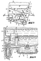
- the actuating lever 19 is designed in this case as a double lever, that is equipped with two arms, of which one arm carries the pressure cushion 40, which acts on the pump diaphragm 56, as before, whereas the second arm is acted upon by the magnet armature 70 of the electromagnet 65.
- the electromagnet 65 is permanently installed in the rear area of the electronics housing 101, and next to it is the circuit board 104, which accommodates the electronics units for controlling the electromagnet 65.
- the lever side of the actuating lever 19, which carries the pressure cushion 40, has an extension 105, in the front area of which the return spring 66 is arranged.
- This return spring 66 essentially has the task of balancing the weight of the magnet armature 70 and thereby largely relieving the pressure on the pump diaphragm 56.
- FIGS. 7 and 8 Since all electrical components should be completely separated from the wet part of the soap dispenser if possible, they are encapsulated, as shown in FIGS. 7 and 8. In the simplest form, this can be done in that the electronics housing 101 is closed towards the front and has only one opening 106, above which the electromagnet 65 is located and into which the actuating lever 19 engages. In this embodiment, as shown in FIG. 7, the electromagnet 65 is accessible from the rear 107 of the electronics housing 101, as is the circuit board 104 and the connecting capacitor 98.
- the sensor plate 71 is arranged on the bottom of the pocket 108 of the electronics housing 101. Above it is the shielding electrode 69, which shields the sensor plate 71 from being influenced by the level of the soap in the reservoir 49. Screws, not shown, are guided through the fastening bores 109 and are used for fastening the electronics housing 101 to a house wall or the like.
- the pocket 108 is provided in its lower region with a conductive layer 110, which prevents the soap dispensing from the dispenser from being impaired by dirtying the underside of the pocket.
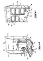
- the insert 68 which is inserted vertically from above into the electronics housing 101, contains the current source, that is to say the electrochemical elements 72. These electrochemical elements are shown as monocells in FIG. 9, but rechargeable batteries can also be used instead.
- the insert 68 is electrically connected via the contact springs 111 to the electronics housing 101, which, as shown in FIG. 10, has contact springs 111. There is a different voltage between the individual contact springs 111, since the electromagnet 65 must be operated at full voltage in order to provide the required power, but the proximity switch 67 as such can be operated at a lower voltage, which saves electricity.
- the proximity switch 67 is composed of the circuit board 104, the connecting capacitor 98 and the sensor plate 71, which are accommodated in the electronics housing 101 according to FIG. 10.
- An adjusting screw 112 made of insulating material enables adjustment of the response distance, i.e. adjusting the height of the shielding electrode 69 in the pocket 108. H. the distance at which the dispenser dispenses soap when the hand approaches the dispenser, ie in the area of the sensor plate 71.
- Receiving bores 113 serve to screw the dispensing container 2 to the electronics housing 101. They are arranged in lugs 114 which are part of the rear side 107 of the electronics housing 101.
- Fig. 7 and Fig. 8 as shown, the electrical parts were encapsulated in that they were enclosed by the electronics housing 101 to the front, that is to the soap dispenser side, so that they could only be reached from the wall side.
- 10 shows the alternative solution here, ie all electrical parts are arranged on the rear side 107 of the electronics housing 101 and are thus openly accessible from the front.
- the cover with respect to the soap dispenser is provided by the insert 68, as shown in FIG. 11, and the front 115 thereof except for the opening 106, through which the actuating lever 19 engages the electromagnet 65 and the long holes 116 is completely closed.
- the locking takes place in the right and left wing 117 of the electronics housing 101 by introducing catch windows 103 and by resilient tabs 119 arranged on the insertion side walls 118, which spring outwards from the insertion side wall 118 and thus engage in the catch windows 103 of the electronics housing 101.
- the electronics housing 101 When inserting the insert 68 into the electronics housing 101, these resilient tabs 119 are pressed inward and only come out again at the catch window 103, where they lock the insert 68 in the intended position.
- the electronics housing 101 only has parts in the area of the pocket 108, which are connected to the proximity switch 67 via the shielding contact 120 and the sensor contact 121.
Landscapes
- Health & Medical Sciences (AREA)
- Public Health (AREA)
- Containers And Packaging Bodies Having A Special Means To Remove Contents (AREA)
- Valve Device For Special Equipments (AREA)
- Polysaccharides And Polysaccharide Derivatives (AREA)
- Reciprocating Pumps (AREA)
- Devices For Dispensing Beverages (AREA)
Claims (7)
Priority Applications (1)
| Application Number | Priority Date | Filing Date | Title |
|---|---|---|---|
| AT83108237T ATE25577T1 (de) | 1982-08-26 | 1983-08-20 | Elektrisch betaetigbare ausgabevorrichtung. |
Applications Claiming Priority (2)
| Application Number | Priority Date | Filing Date | Title |
|---|---|---|---|
| DE3231842A DE3231842C2 (de) | 1982-08-26 | 1982-08-26 | Elektrisch betätigbare Ausgabevorrichtung |
| DE3231842 | 1982-08-26 |
Publications (3)
| Publication Number | Publication Date |
|---|---|
| EP0103765A2 EP0103765A2 (fr) | 1984-03-28 |
| EP0103765A3 EP0103765A3 (en) | 1985-01-23 |
| EP0103765B1 true EP0103765B1 (fr) | 1987-03-04 |
Family
ID=6171806
Family Applications (1)
| Application Number | Title | Priority Date | Filing Date |
|---|---|---|---|
| EP83108237A Expired EP0103765B1 (fr) | 1982-08-26 | 1983-08-20 | Installation de distribution commandée électriquement |
Country Status (3)
| Country | Link |
|---|---|
| EP (1) | EP0103765B1 (fr) |
| AT (1) | ATE25577T1 (fr) |
| DE (2) | DE3231842C2 (fr) |
Cited By (2)
| Publication number | Priority date | Publication date | Assignee | Title |
|---|---|---|---|---|
| DE3819412A1 (de) * | 1988-06-07 | 1989-12-21 | Schulze Karl Heinz | Dosierbarer fluessigkeitsspender |
| RU2735633C1 (ru) * | 2020-05-25 | 2020-11-05 | Людмила Андреевна Караогланова | Бесконтактная автоматическая система для санитарно-гигиенической обработки кожного покрова |
Families Citing this family (6)
| Publication number | Priority date | Publication date | Assignee | Title |
|---|---|---|---|---|
| AU582491B2 (en) * | 1986-03-06 | 1989-03-23 | Warwick Alan Bell | A drum lifting device |
| DE3836189A1 (de) * | 1988-10-24 | 1990-04-26 | Luettichau Conrad Reichsgraf V | Vorrichtung zur abgabe einer vorbestimmten menge eines fliessfaehigen mediums in einen fluessigkeitsbehaelter, oder dergleichen |
| DE3902476A1 (de) * | 1989-01-27 | 1990-08-02 | Feldmuehle Ag | Ausgabevorrichtung fuer fluessige oder pastoese gueter |
| PL163791B1 (pl) * | 1991-02-20 | 1994-05-31 | Feliks Jalowski | Zawór odcinajacy sterowany elektronicznie PL PL PL PL |
| CN102616419B (zh) * | 2011-01-27 | 2013-10-23 | 宁波市镇海西门专利技术开发有限公司 | 挤牙膏器 |
| DE102021003193A1 (de) | 2021-06-21 | 2022-12-22 | Anna Czapka | elektrische Spendervorrichtung fur Trockenseife |
Family Cites Families (4)
| Publication number | Priority date | Publication date | Assignee | Title |
|---|---|---|---|---|
| US3327901A (en) | 1963-12-13 | 1967-06-27 | Jet Dispenser Corp | Dispenser |
| US3273752A (en) * | 1965-02-11 | 1966-09-20 | Geza E Horeczky | Photo-electric controlled dispenser |
| DE2851886C2 (de) * | 1978-11-30 | 1981-01-29 | Dagma Deutsche Automaten- Und Getraenkemaschinen Gmbh & Co Kg, 2067 Reinfeld | Vorrichtung zur dosierten Abgabe von Flüssigkeiten |
| US4316555A (en) * | 1980-03-03 | 1982-02-23 | Steiner Corporation | System for dispensing fluids |
-
1982
- 1982-08-26 DE DE3231842A patent/DE3231842C2/de not_active Expired
-
1983
- 1983-08-20 AT AT83108237T patent/ATE25577T1/de active
- 1983-08-20 EP EP83108237A patent/EP0103765B1/fr not_active Expired
- 1983-08-20 DE DE8383108237T patent/DE3369903D1/de not_active Expired
Cited By (2)
| Publication number | Priority date | Publication date | Assignee | Title |
|---|---|---|---|---|
| DE3819412A1 (de) * | 1988-06-07 | 1989-12-21 | Schulze Karl Heinz | Dosierbarer fluessigkeitsspender |
| RU2735633C1 (ru) * | 2020-05-25 | 2020-11-05 | Людмила Андреевна Караогланова | Бесконтактная автоматическая система для санитарно-гигиенической обработки кожного покрова |
Also Published As
| Publication number | Publication date |
|---|---|
| EP0103765A2 (fr) | 1984-03-28 |
| DE3369903D1 (en) | 1987-04-09 |
| DE3231842A1 (de) | 1984-03-01 |
| DE3231842C2 (de) | 1984-06-14 |
| EP0103765A3 (en) | 1985-01-23 |
| ATE25577T1 (de) | 1987-03-15 |
Similar Documents
| Publication | Publication Date | Title |
|---|---|---|
| EP0455679B1 (fr) | Distributeur de materiaux liquides ou pateux | |
| DE60317072T2 (de) | Verdampfer | |
| EP0777077A1 (fr) | Distributeur à graisse pour délivrance commandé par moteur électrique d'une graisse à une machine | |
| DE3231842C2 (de) | Elektrisch betätigbare Ausgabevorrichtung | |
| DE2734287A1 (de) | Verfahren und vorrichtung zum reinigen von gegenstaenden | |
| DE68901666T2 (de) | Waermebehaelter fuer fluessigkeiten, fette produkte, gele und aehnliches. | |
| EP0419613A1 (fr) | Appareil d'entretien pour lentilles de contact. | |
| EP0104422B1 (fr) | Distributeur commandé électriquement | |
| DE3249421C2 (de) | Elektrisch betätigbare Ausgabevorrichtung | |
| DE3400575A1 (de) | Durch gleichspannung mittels eines kapazitiven naeherungsschalters betaetigbare ausgabevorrichtung | |
| EP0856692A1 (fr) | Dispositif de positionnement de la queue d'une soupage | |
| DE3738792C2 (fr) | ||
| DE102021124705B4 (de) | Vorrichtung zur Desinfektion einer eine Türklinke drückenden Hand | |
| DE3036523C2 (de) | Ausgabevorrichtung für flüssige oder pastöse Güter | |
| DE4211494A1 (de) | Dispenser, insbesondere für Flüssigseife | |
| DE3101020A1 (de) | "portionenspender fuer fluessiges medium sowie dessen verwendung" | |
| DE69903435T2 (de) | Spender für abgabe einer viskosen substanz, z.b. einer antiseptischen flüssigkeit, und behälter für solchen spender | |
| DE1921187U (de) | Selbsttaetige abgabevorrichtung fuer eine hilfsfluessigkeit. | |
| DE102004044089A1 (de) | Ladegerät für Elektrokleingeräte | |
| DE2851886B1 (de) | Vorrichtung zur dosierten Abgabe von Fluessigkeiten | |
| DE3036589A1 (de) | Ausgabevorrichtung fuer fluessige oder pastoese gueter | |
| EP3721764B1 (fr) | Distributeur de produit plat de bande, en particulier en papier, ou pour distribuer un fluide | |
| DE3036493A1 (de) | Ausgabevorrichtung fuer fluessige oder pastoese gueter | |
| DE29622484U1 (de) | Tropfinfusionsalarm | |
| DE202025108007U1 (de) | Haustier-Trinkwasserspender mit Halterung |
Legal Events
| Date | Code | Title | Description |
|---|---|---|---|
| PUAI | Public reference made under article 153(3) epc to a published international application that has entered the european phase |
Free format text: ORIGINAL CODE: 0009012 |
|
| 17P | Request for examination filed |
Effective date: 19830909 |
|
| AK | Designated contracting states |
Designated state(s): AT BE CH DE FR GB IT LI LU NL SE |
|
| PUAL | Search report despatched |
Free format text: ORIGINAL CODE: 0009013 |
|
| AK | Designated contracting states |
Designated state(s): AT BE CH DE FR GB IT LI LU NL SE |
|
| 17Q | First examination report despatched |
Effective date: 19860320 |
|
| ITF | It: translation for a ep patent filed | ||
| GRAA | (expected) grant |
Free format text: ORIGINAL CODE: 0009210 |
|
| AK | Designated contracting states |
Kind code of ref document: B1 Designated state(s): AT BE CH DE FR GB IT LI LU NL SE |
|
| REF | Corresponds to: |
Ref document number: 25577 Country of ref document: AT Date of ref document: 19870315 Kind code of ref document: T |
|
| ET | Fr: translation filed | ||
| REF | Corresponds to: |
Ref document number: 3369903 Country of ref document: DE Date of ref document: 19870409 |
|
| PLBE | No opposition filed within time limit |
Free format text: ORIGINAL CODE: 0009261 |
|
| STAA | Information on the status of an ep patent application or granted ep patent |
Free format text: STATUS: NO OPPOSITION FILED WITHIN TIME LIMIT |
|
| 26N | No opposition filed | ||
| ITPR | It: changes in ownership of a european patent |
Owner name: CESSIONE;SCOTT FELDMUEHLE GMBH |
|
| REG | Reference to a national code |
Ref country code: CH Ref legal event code: PUE Owner name: SCOTT-FELDMUEHLE GMBH |
|
| ITTA | It: last paid annual fee | ||
| NLS | Nl: assignments of ep-patents |
Owner name: SCOTT-FELDMUEHLE GMBH TE DUESSELDORF, BONDSREPUBLI |
|
| REG | Reference to a national code |
Ref country code: FR Ref legal event code: TP |
|
| REG | Reference to a national code |
Ref country code: GB Ref legal event code: 732 |
|
| PGFP | Annual fee paid to national office [announced via postgrant information from national office to epo] |
Ref country code: GB Payment date: 19930616 Year of fee payment: 11 Ref country code: FR Payment date: 19930616 Year of fee payment: 11 |
|
| PGFP | Annual fee paid to national office [announced via postgrant information from national office to epo] |
Ref country code: SE Payment date: 19930621 Year of fee payment: 11 Ref country code: LU Payment date: 19930621 Year of fee payment: 11 Ref country code: AT Payment date: 19930621 Year of fee payment: 11 |
|
| PGFP | Annual fee paid to national office [announced via postgrant information from national office to epo] |
Ref country code: BE Payment date: 19930705 Year of fee payment: 11 |
|
| PGFP | Annual fee paid to national office [announced via postgrant information from national office to epo] |
Ref country code: CH Payment date: 19930715 Year of fee payment: 11 |
|
| PGFP | Annual fee paid to national office [announced via postgrant information from national office to epo] |
Ref country code: DE Payment date: 19930825 Year of fee payment: 11 |
|
| PGFP | Annual fee paid to national office [announced via postgrant information from national office to epo] |
Ref country code: NL Payment date: 19930831 Year of fee payment: 11 |
|
| EPTA | Lu: last paid annual fee | ||
| PG25 | Lapsed in a contracting state [announced via postgrant information from national office to epo] |
Ref country code: LU Free format text: LAPSE BECAUSE OF NON-PAYMENT OF DUE FEES Effective date: 19940820 Ref country code: GB Effective date: 19940820 Ref country code: AT Effective date: 19940820 |
|
| PG25 | Lapsed in a contracting state [announced via postgrant information from national office to epo] |
Ref country code: SE Effective date: 19940821 |
|
| PG25 | Lapsed in a contracting state [announced via postgrant information from national office to epo] |
Ref country code: LI Effective date: 19940831 Ref country code: CH Effective date: 19940831 Ref country code: BE Effective date: 19940831 |
|
| EAL | Se: european patent in force in sweden |
Ref document number: 83108237.5 |
|
| BERE | Be: lapsed |
Owner name: SCOTT-FELDMUHLE G.M.B.H. Effective date: 19940831 |
|
| PG25 | Lapsed in a contracting state [announced via postgrant information from national office to epo] |
Ref country code: NL Effective date: 19950301 |
|
| NLV4 | Nl: lapsed or anulled due to non-payment of the annual fee | ||
| GBPC | Gb: european patent ceased through non-payment of renewal fee |
Effective date: 19940820 |
|
| PG25 | Lapsed in a contracting state [announced via postgrant information from national office to epo] |
Ref country code: FR Effective date: 19950428 |
|
| REG | Reference to a national code |
Ref country code: CH Ref legal event code: PL |
|
| PG25 | Lapsed in a contracting state [announced via postgrant information from national office to epo] |
Ref country code: DE Effective date: 19950503 |
|
| EUG | Se: european patent has lapsed |
Ref document number: 83108237.5 |
|
| REG | Reference to a national code |
Ref country code: FR Ref legal event code: ST |