EP0103794B1 - Diaphragme pour un appareil d'examen à rayons X - Google Patents
Diaphragme pour un appareil d'examen à rayons X Download PDFInfo
- Publication number
- EP0103794B1 EP0103794B1 EP83108639A EP83108639A EP0103794B1 EP 0103794 B1 EP0103794 B1 EP 0103794B1 EP 83108639 A EP83108639 A EP 83108639A EP 83108639 A EP83108639 A EP 83108639A EP 0103794 B1 EP0103794 B1 EP 0103794B1
- Authority
- EP
- European Patent Office
- Prior art keywords
- diaphragm
- ray
- bundle
- plates
- rays
- Prior art date
- Legal status (The legal status is an assumption and is not a legal conclusion. Google has not performed a legal analysis and makes no representation as to the accuracy of the status listed.)
- Expired
Links
Images
Classifications
-
- G—PHYSICS
- G21—NUCLEAR PHYSICS; NUCLEAR ENGINEERING
- G21K—HANDLING OF PARTICLES OR IONISING RADIATION NOT OTHERWISE PROVIDED FOR; IRRADIATION DEVICES; GAMMA RAY OR X-RAY MICROSCOPES
- G21K1/00—Arrangements for handling particles or ionising radiation, e.g. focusing or moderating
- G21K1/02—Arrangements for handling particles or ionising radiation, e.g. focusing or moderating using diaphragms, collimators
- G21K1/04—Arrangements for handling particles or ionising radiation, e.g. focusing or moderating using diaphragms, collimators using variable diaphragms, shutters, choppers
-
- A—HUMAN NECESSITIES
- A61—MEDICAL OR VETERINARY SCIENCE; HYGIENE
- A61B—DIAGNOSIS; SURGERY; IDENTIFICATION
- A61B6/00—Apparatus or devices for radiation diagnosis; Apparatus or devices for radiation diagnosis combined with radiation therapy equipment
- A61B6/54—Control of apparatus or devices for radiation diagnosis
- A61B6/548—Remote control of the apparatus or devices
Definitions
- the invention relates to a radiation diaphragm for an X-ray examination apparatus with a plurality of diaphragm plates which can be adjusted in pairs and are adjustable in pairs, a beam bundle of rectangular cross-section and of different sizes, with additional diaphragm plates which can be pivoted into the four corner regions of the beam bundle for the insertion of an approximately circular beam bundle of variable diameter and with an actuator for the additional swiveling cover plates.
- the US-PS 26 75 486 discloses a radiation diaphragm for X-rays, in which four diaphragm plates are slidably mounted against each other in a plane perpendicular to the central beam. With this aperture, only rectangular beams of different sizes can be faded in.
- X-ray image intensifiers - which are known to have a round fluorescent entrance screen - with full illumination of the field of the entrance fluorescent screen behind such beam apertures, 30% overexposure is obtained at the corners of the rectangular beam. This overexposure reduces the contrast of the X-ray image and increases the patient's radiation exposure.
- DE-AS 10 37 035 also discloses a radiation diaphragm developed for radiation therapy, in which the four diaphragm plates, each of which is slidably mounted in a plane, are divided diagonally. The two approximately triangular halves of each diaphragm plate can be moved against each other with this beam diaphragm with a spindle.
- This radiation diaphragm which allows the display of square to maximally octagonal fields, is quite complex both in terms of its manufacture and its operation, in which five rotary handles can be adjusted independently of one another.
- a radiation shield which allows a rectangular beam to be faded in, is sold by Philips.
- the overexposure of a circular luminescent entrance screen can be reduced in that, if necessary, additional diaphragm plates are pivoted into the beam cone in at least two different planes. It is a peculiarity of this radiation diaphragm that the additional diaphragm plates must be arranged in at least two different levels so that they do not interfere with one another in small fields.
- the remaining overexposure of a round fluorescent entrance screen is dependent on the diameter of the beam of rays that is faded in.
- the invention has for its object to provide a radiation diaphragm for X-ray examination devices with which both rectangular and approximately circular radiation fields can be faded in. Any remaining glare from a circular entrance screen should be as small as possible and of the same size for all diameters.
- the radiation shield should be suitable for remote control and should therefore be as smooth as possible. In addition, the radiation shield should take up as little space as possible in the beam direction, be as light as possible and be maintenance-free.
- the additional diaphragm plates according to the invention therefore have an essentially triangular outline, are via a parallelogram linkage each from a waiting position located to the side of the maximum cross-section of the beam that can be faded in, near its corners, with a beam facing the beam, perpendicular to the bisector of the respective corner aligned edges can be pivoted approximately radially to the axis of symmetry of the radiation diaphragm.
- the field of application of the radiation diaphragm can be expanded considerably, if in particular
- all additional diaphragm plates can be displaced along paths to the axis of symmetry of the radiation diaphragm, on which they reach the axis of symmetry from the point of view of the axis of symmetry with the same corner in each case. This has the consequence that the additional diaphragm plates do not interfere with one another when arranged in a single plane, even when the radiation field is strongly superimposed. Any small, approximately circular radiation fields can thus be faded in.
- two pairs of diaphragm plates are adjustable twice perpendicular to the axis of symmetry 13 of the beam diaphragm 5.
- a mirror 14 which is positioned obliquely to the axis of symmetry 13 of the beam diaphragm, is arranged in the housing 6 of the beam diaphragm 5 in the area of the beam bundle 3 between the diaphragm plates near the focus and away from the focus.
- a light source (not shown) is aligned in the housing 6 of the radiation diaphragm to the mirror in such a way that the light cone 15 reflected by the mirror 14 is faded in congruently with the X-ray beam 3 through the diaphragm plates 10, 11, 12 away from the focus.
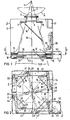
- the housing 6 of the radiation diaphragm 5 carries an inner frame 16 in a plane located immediately behind the diaphragm plates 10, 11, 12 close to the focus, on which, as shown in FIG. 2, eight boom rods 17, 18, 19, 20, 21, 22 , 23, 24 are pivoted in pairs about axes 25, 26, 27, 28, 29, 30, 31, 32 aligned parallel to the axis of symmetry 13 of the radiation diaphragm.
- An additional triangular diaphragm plate 33, 34, 35, 36 is pivotally mounted on the free ends of a pair of boom rods.
- Two extension rods each form, together with the additional diaphragm plate and the inner frame 16, a parallelogram linkage with which the additional diaphragm plate can be pivoted into the beam 3.
- the additional diaphragm plates are each pivotable on a quarter circle from a corner of the inner frame 16 of the diaphragm to the axis of symmetry 13 of the diaphragm.
- the orientation of the additional diaphragm plates 33, 34, 35, 36 is selected so that it limits the beam with the edge 37, 38, 39, 40, which is aligned perpendicular to the bisector of the respective corner of the rectangular beam 3.
- the two other edges of each additional, triangular diaphragm plate are adapted to the corner area of the inner frame.
- the four additional diaphragm plates reach the axis of symmetry 13 of the beam diaphragm 5, each with one and the same corner. In the exemplary embodiment in FIG. 2, from the perspective of the axis of symmetry 13, this is the left corner.
- one of the two boom rods of a parallelogram linkage is coupled to a toothed belt pulley 41, 42, 43, 44.
- An endless toothed belt 45 is stretched around all four toothed belt pulleys of the extension rod.
- this endless toothed belt is guided over a toothed belt pulley 46, which can be driven by a motor 47 via a gear 48.
- one of the diaphragm plates which are distant from the focus and are responsible for rectangular blanking is coupled to a spring-loaded cable pull 49, via which a path-dependent analog-digital converter 50 can be adjusted.
- Its coded signals are present at an input of a differential stage 51.
- the motor 47 is also coupled to a path-dependent analog-digital converter 52. Its signals are also present at an input of differential stage 51.
- the radiation diaphragm 5 can be used like any other radiation diaphragm.
- the opening of the beam can be changed in a manner known per se by synchronously adjusting the diaphragm plates 7, 8, 9, 10, 11, 12 arranged close to and out of focus in the beam direction.
- the near-focus and far-away aperture plates block out a rectangular radiation field of different lengths and widths.
- the additional diaphragm plates 33, 34, 35, 36 are in the waiting position indicated by dashed lines in FIG. 2, in which, in the illustration in FIG. 2, they are pivoted under the inner frame 16.
- the width of the rectangular one hidden beam can thus be adjusted in width and height at will to the dimensions of the examination area or to the selected cassette or film format.
- the opening of the radiation cone is also faded in by adjusting the aperture plates 7, 8, 9, 10, 11, 12 near and out of focus to the diameter of the input fluorescent screen of the X-ray image intensifier (not shown).
- the square radiation field set in this way would outshine the round input fluorescent screen of the X-ray image intensifier in the area of its four corners.
- the motor 47 can be switched on, for example, via a relay (not shown) which responds when switching to image intensifier operation.
- the toothed belt 45 is rotated via the motor 47 and the toothed belt pulleys 41, 42, 43, 44 of the cantilever rods are rotated so far until the signals generated by the path-dependent analog-digital converter 52 of the motor 47 and applied to the differential stage 51 are the same as those are applied to the differential stage 51 by the path-dependent analog-to-digital converter 50 of the diaphragm plate 11 remote from the focus.
- a stepper motor can be used and instead of differential stage 51 a pulse counter can be used, which is counted down by one unit with each step of the stepper motor and from which the motor is switched off when the counter is at zero.
Landscapes
- Physics & Mathematics (AREA)
- Spectroscopy & Molecular Physics (AREA)
- Engineering & Computer Science (AREA)
- General Engineering & Computer Science (AREA)
- High Energy & Nuclear Physics (AREA)
- Apparatus For Radiation Diagnosis (AREA)
Claims (8)
Applications Claiming Priority (2)
| Application Number | Priority Date | Filing Date | Title |
|---|---|---|---|
| DE19823234410 DE3234410A1 (de) | 1982-09-16 | 1982-09-16 | Strahlenblende fuer ein roentgenuntersuchungsgeraet |
| DE3234410 | 1982-09-16 |
Publications (3)
| Publication Number | Publication Date |
|---|---|
| EP0103794A2 EP0103794A2 (fr) | 1984-03-28 |
| EP0103794A3 EP0103794A3 (en) | 1986-02-05 |
| EP0103794B1 true EP0103794B1 (fr) | 1988-03-16 |
Family
ID=6173415
Family Applications (1)
| Application Number | Title | Priority Date | Filing Date |
|---|---|---|---|
| EP83108639A Expired EP0103794B1 (fr) | 1982-09-16 | 1983-09-01 | Diaphragme pour un appareil d'examen à rayons X |
Country Status (3)
| Country | Link |
|---|---|
| US (1) | US4514859A (fr) |
| EP (1) | EP0103794B1 (fr) |
| DE (2) | DE3234410A1 (fr) |
Families Citing this family (14)
| Publication number | Priority date | Publication date | Assignee | Title |
|---|---|---|---|---|
| US4875225A (en) * | 1987-02-16 | 1989-10-17 | Siemens Aktiengesellschaft | X-ray video system and method for the transillumination of an examination subject |
| DE8711572U1 (de) * | 1987-08-26 | 1988-12-22 | Siemens AG, 1000 Berlin und 8000 München | Primärstrahlenblende für Röntgendiagnostikgeräte |
| US5396534A (en) * | 1993-10-12 | 1995-03-07 | Thomas; Howard C. | Shutter apparatus for collimating x-rays |
| SE508661C2 (sv) * | 1994-12-19 | 1998-10-26 | Elekta Instr Ab | Anordning för strålbegränsning |
| DE19536432A1 (de) * | 1995-09-29 | 1997-04-03 | Siemens Ag | Strahlenblende für ein Röntgendiagnostikgerät |
| DE10162256B4 (de) * | 2001-12-18 | 2004-09-09 | Siemens Ag | Strahlenblende für ein Röntgengerät |
| DE10259696B4 (de) * | 2002-12-18 | 2018-07-05 | Immobiliengesellschaft Helmut Fischer Gmbh & Co. Kg | Vorrichtung zum Messen der Dicke dünner Schichten |
| EP1677679A1 (fr) * | 2003-10-03 | 2006-07-12 | Xoran Technologies, Inc. | Systeme d'imagerie par tomodensitometrie utilise pour une intervention robotique |
| FR2862805B1 (fr) * | 2004-11-19 | 2007-01-26 | Ge Med Sys Global Tech Co Llc | Collimateur, irradiateur a rayons x et appareil a rayons x |
| US8085903B2 (en) * | 2008-09-10 | 2011-12-27 | Thomas Howard C | Shutter mechanism for collimating X-rays |
| CN102307527B (zh) * | 2009-02-10 | 2013-08-21 | 皇家飞利浦电子股份有限公司 | 用于显示x射线图像的医学查看系统 |
| CN101859608B (zh) * | 2009-04-09 | 2014-07-09 | Ge医疗系统环球技术有限公司 | 刀片装置及x射线成像仪 |
| US8942346B2 (en) | 2012-03-29 | 2015-01-27 | General Electric Company | Systems and methods for obtaining and displaying an X-ray image |
| CN114098783A (zh) * | 2022-01-28 | 2022-03-01 | 深圳市创谷科技发展有限公司 | 限束器、x光机及控制方法 |
Family Cites Families (7)
| Publication number | Priority date | Publication date | Assignee | Title |
|---|---|---|---|---|
| FR522956A (fr) * | 1919-04-25 | 1921-08-09 | Robert Louis Ernest Casel | Diaphragme radiologique |
| US2675486A (en) * | 1951-12-08 | 1954-04-13 | Ca Atomic Energy Ltd | Beam therapy collimating unit |
| DE1037035B (de) * | 1956-07-18 | 1958-08-21 | Atomic Energy Of Canada Ltd | Kollimator zur Abgrenzung energiereicher Strahlung, insbesondere ª†-Strahlung |
| US3048700A (en) * | 1959-09-24 | 1962-08-07 | Westinghouse Electric Corp | X-ray shutter apparatus |
| DE2053089C3 (de) * | 1970-10-29 | 1980-02-07 | Siemens Ag, 1000 Berlin U. 8000 Muenchen | Strahlenblende fur Röntgenstrahlen |
| US4086494A (en) * | 1976-12-17 | 1978-04-25 | Malak Stephen P | Radiation collimator for use with high energy radiation beams |
| US4246488A (en) * | 1979-03-09 | 1981-01-20 | Picker Corporation | Radiation collimator |
-
1982
- 1982-09-16 DE DE19823234410 patent/DE3234410A1/de not_active Withdrawn
-
1983
- 1983-07-12 US US06/513,016 patent/US4514859A/en not_active Expired - Lifetime
- 1983-09-01 DE DE8383108639T patent/DE3376041D1/de not_active Expired
- 1983-09-01 EP EP83108639A patent/EP0103794B1/fr not_active Expired
Also Published As
| Publication number | Publication date |
|---|---|
| EP0103794A3 (en) | 1986-02-05 |
| DE3234410A1 (de) | 1984-03-22 |
| DE3376041D1 (en) | 1988-04-21 |
| US4514859A (en) | 1985-04-30 |
| EP0103794A2 (fr) | 1984-03-28 |
Similar Documents
| Publication | Publication Date | Title |
|---|---|---|
| EP0103794B1 (fr) | Diaphragme pour un appareil d'examen à rayons X | |
| DE69605730T2 (de) | Eine kollimatoreinheit enthaltende röntgenstrahluntersuchungsvorrichtung | |
| EP0371303A1 (fr) | Appareil d'actinothérapie | |
| DE2815252A1 (de) | Variabler kollimator | |
| DE7710947U1 (de) | Röntgenuntersuchungsgerät | |
| DE2053089C3 (de) | Strahlenblende fur Röntgenstrahlen | |
| DE3138939A1 (de) | Roentgenuntersuchungsgeraet | |
| DE102006010726A1 (de) | Computertomographiesystem mit einstellbarer Brennfleck-zu-Detektor-Distanz | |
| DE2926925C2 (de) | Optische Lichtübertragungsvorrichtung | |
| DE3136806A1 (de) | Roentgenuntersuchungsgeraet | |
| DE2446680B2 (de) | Tubus zur Begrenzung eines Bündels durchdringender Strahlen | |
| EP0166030B1 (fr) | Diaphragme pour le rayonnement X primaire d'un appareil de radiodiagnostic pour prises de vue stéréoradiographiques | |
| DE4435112A1 (de) | Verfahren und Vorrichtung zum Ausrichten einer Röntgenkassette | |
| EP0184695B1 (fr) | Diaphragme pour rayonnement primaire dans un appareil d'examen radiologique | |
| EP0074021B1 (fr) | Appareil d'examen radiologique | |
| EP0343430B1 (fr) | Distributeur de lumière pour installation de diagnostic à rayons X | |
| DE4228082C1 (en) | Aperture esp. for X=ray beam - has aperture plate elastically conformable to test object shape | |
| DE8226150U1 (de) | Strahlenblende für ein Röntgenuntersuchungsgerät | |
| EP0995398A1 (fr) | Appareil d'examen par rayons X | |
| DE102009047672B4 (de) | Röntgenoptischer Aufbau mit zwei fokussierenden Elementen | |
| DE3236082A1 (de) | Strahlenblende fuer ein roentgenuntersuchungsgeraet | |
| DE2842659A1 (de) | Roentgenzielgeraet | |
| DE202023103001U1 (de) | Kollimator für eine Röntgenstrahlung | |
| DE1441312A1 (de) | An einem Roentgenroehrengehaeuse angebrachte Primaerstrahlenblende | |
| DE2615335A1 (de) | Primaerstrahlenblende |
Legal Events
| Date | Code | Title | Description |
|---|---|---|---|
| PUAI | Public reference made under article 153(3) epc to a published international application that has entered the european phase |
Free format text: ORIGINAL CODE: 0009012 |
|
| AK | Designated contracting states |
Designated state(s): DE FR GB IT |
|
| PUAL | Search report despatched |
Free format text: ORIGINAL CODE: 0009013 |
|
| AK | Designated contracting states |
Designated state(s): DE FR GB IT |
|
| 17P | Request for examination filed |
Effective date: 19860226 |
|
| 17Q | First examination report despatched |
Effective date: 19870806 |
|
| GRAA | (expected) grant |
Free format text: ORIGINAL CODE: 0009210 |
|
| AK | Designated contracting states |
Kind code of ref document: B1 Designated state(s): DE FR GB IT |
|
| PG25 | Lapsed in a contracting state [announced via postgrant information from national office to epo] |
Ref country code: IT Free format text: LAPSE BECAUSE OF FAILURE TO SUBMIT A TRANSLATION OF THE DESCRIPTION OR TO PAY THE FEE WITHIN THE PRESCRIBED TIME-LIMIT;WARNING: LAPSES OF ITALIAN PATENTS WITH EFFECTIVE DATE BEFORE 2007 MAY HAVE OCCURRED AT ANY TIME BEFORE 2007. THE CORRECT EFFECTIVE DATE MAY BE DIFFERENT FROM THE ONE RECORDED. Effective date: 19880316 |
|
| REF | Corresponds to: |
Ref document number: 3376041 Country of ref document: DE Date of ref document: 19880421 |
|
| ET | Fr: translation filed | ||
| GBT | Gb: translation of ep patent filed (gb section 77(6)(a)/1977) | ||
| PLBE | No opposition filed within time limit |
Free format text: ORIGINAL CODE: 0009261 |
|
| STAA | Information on the status of an ep patent application or granted ep patent |
Free format text: STATUS: NO OPPOSITION FILED WITHIN TIME LIMIT |
|
| 26N | No opposition filed | ||
| PGFP | Annual fee paid to national office [announced via postgrant information from national office to epo] |
Ref country code: GB Payment date: 19940815 Year of fee payment: 12 |
|
| PGFP | Annual fee paid to national office [announced via postgrant information from national office to epo] |
Ref country code: FR Payment date: 19940920 Year of fee payment: 12 |
|
| PG25 | Lapsed in a contracting state [announced via postgrant information from national office to epo] |
Ref country code: GB Effective date: 19950901 |
|
| GBPC | Gb: european patent ceased through non-payment of renewal fee |
Effective date: 19950901 |
|
| PG25 | Lapsed in a contracting state [announced via postgrant information from national office to epo] |
Ref country code: FR Effective date: 19960531 |
|
| REG | Reference to a national code |
Ref country code: FR Ref legal event code: ST |
|
| PGFP | Annual fee paid to national office [announced via postgrant information from national office to epo] |
Ref country code: DE Payment date: 20011119 Year of fee payment: 19 |
|
| PG25 | Lapsed in a contracting state [announced via postgrant information from national office to epo] |
Ref country code: DE Free format text: LAPSE BECAUSE OF NON-PAYMENT OF DUE FEES Effective date: 20030401 |