EP0103802A2 - Apparatus for determining contact-tension in pretensioned tools - Google Patents
Apparatus for determining contact-tension in pretensioned tools Download PDFInfo
- Publication number
- EP0103802A2 EP0103802A2 EP83108738A EP83108738A EP0103802A2 EP 0103802 A2 EP0103802 A2 EP 0103802A2 EP 83108738 A EP83108738 A EP 83108738A EP 83108738 A EP83108738 A EP 83108738A EP 0103802 A2 EP0103802 A2 EP 0103802A2
- Authority
- EP
- European Patent Office
- Prior art keywords
- guide
- sleeve
- parallel
- base
- sensor
- Prior art date
- Legal status (The legal status is an assumption and is not a legal conclusion. Google has not performed a legal analysis and makes no representation as to the accuracy of the status listed.)
- Granted
Links
Images

Classifications
-
- G—PHYSICS
- G01—MEASURING; TESTING
- G01M—TESTING STATIC OR DYNAMIC BALANCE OF MACHINES OR STRUCTURES; TESTING OF STRUCTURES OR APPARATUS, NOT OTHERWISE PROVIDED FOR
- G01M99/00—Subject matter not provided for in other groups of this subclass
-
- G—PHYSICS
- G01—MEASURING; TESTING
- G01L—MEASURING FORCE, STRESS, TORQUE, WORK, MECHANICAL POWER, MECHANICAL EFFICIENCY, OR FLUID PRESSURE
- G01L1/00—Measuring force or stress, in general
- G01L1/25—Measuring force or stress, in general using wave or particle radiation, e.g. X-rays, microwaves, neutrons
- G01L1/255—Measuring force or stress, in general using wave or particle radiation, e.g. X-rays, microwaves, neutrons using acoustic waves, or acoustic emission
-
- G—PHYSICS
- G01—MEASURING; TESTING
- G01L—MEASURING FORCE, STRESS, TORQUE, WORK, MECHANICAL POWER, MECHANICAL EFFICIENCY, OR FLUID PRESSURE
- G01L5/00—Apparatus for, or methods of, measuring force, work, mechanical power, or torque, specially adapted for specific purposes
- G01L5/0047—Apparatus for, or methods of, measuring force, work, mechanical power, or torque, specially adapted for specific purposes measuring forces due to residual stresses
-
- G—PHYSICS
- G01—MEASURING; TESTING
- G01N—INVESTIGATING OR ANALYSING MATERIALS BY DETERMINING THEIR CHEMICAL OR PHYSICAL PROPERTIES
- G01N29/00—Investigating or analysing materials by the use of ultrasonic, sonic or infrasonic waves; Visualisation of the interior of objects by transmitting ultrasonic or sonic waves through the object
- G01N29/22—Details, e.g. general constructional or apparatus details
- G01N29/24—Probes
-
- G—PHYSICS
- G01—MEASURING; TESTING
- G01N—INVESTIGATING OR ANALYSING MATERIALS BY DETERMINING THEIR CHEMICAL OR PHYSICAL PROPERTIES
- G01N2291/00—Indexing codes associated with group G01N29/00
- G01N2291/02—Indexing codes associated with the analysed material
- G01N2291/028—Material parameters
- G01N2291/02827—Elastic parameters, strength or force
Definitions
- the invention relates to a device for determining the contact voltages in prestressed tools with a base and with two rotatable, oppositely arranged, exchangeable tips, one of which is held on a rotatable axis and the other on a screw via a bearing, and each of which one Plate is assigned, which are arranged parallel to each other and connected to each other and between which a trough with an acoustic medium is provided, on the bottom of which an axially movable guide is attached, which has an opening with a sensor which is connected to a measuring device.
- a device for the determination of contact voltages is known (BG-PS 28 809), which consists of two movable opposite tips, between which the element to be checked is inserted.
- One tip is attached to a rotatable axis.
- the other tip sits on a screw above a bearing. Both tips are mounted in two parallel plates.
- the axis and the screw are connected by a bracket.
- On the base there is a tub with an acoustic medium between the plates.
- An axially movable guide with an opening extends through the base and the trough bottom, into which an ultrasonic sensor is inserted, which is connected to a measuring device.
- the disadvantage of this device is the constant manual readjustment of the distance between the controlled element and the sensor for each individual measurement.
- the invention has for its object to design the device of the type mentioned in such a way that the errors of the subjective setting in the individual measurements are avoided by automatic operation.
- the device according to the invention has the advantage that the determination of the contact voltages and thus the zer trouble-free control of pretensioned tools can be carried out automatically, whereby deviations in the excess of the seat in the pretensioned tools can be determined quickly.
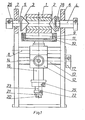
- the controlled pretensioned forming tool 1 is fixed between two movable, interchangeable, rotatable tips 2 and 3.
- the tip 2 sits with a bearing 28 on a screw 4.
- the tip 3 sits on a rotatable axis 5 with a handle 26.
- the screw 4 sits in a plate 6.
- the axis 5 is mounted in a plate 7 parallel to the plate 6.
- the plates 6 and 7 are connected by parallel guides 8.
- the tool 1 is in contact with parallel rotating rollers 9 which are mounted in a trough 10 which is filled with an acoustic medium 11.
- a sleeve 16 is fastened via a guide screw 14 and a nut 15, to which a bushing 25 is rigidly fastened.
- the drive screw 13 enables a progressive movement of the base 12, the sleeve 16 and the assembly, which consists of the parallel rollers 9, of a sensor 18 which is axially movable in an opening by means of a limiting bush 20 and a lock nut 21 via a handle 17
- Guide 19 is fixed, consists of a second nut 22 and from the tub 10 with the acoustic medium 11, which is firmly connected to the guide bush 23, which has a radial play 27 with respect to the sleeve 16.
- the elements of the assembly are suspended on the sleeve 16 via a spring 24, which with its lower end on the Guide bush 23 is attached.
- the device works as follows: The controlled pretensioned tool 1 is inserted between the tips 2 and 3 and tightened with the screw 4.
- the coarse adjustment of the sensor 18 with respect to the tool 1 is carried out by moving the sleeve 16 in the vertical direction with the aid of the bushing 25 until a desired pressing force is given between the rollers 9 and the tool 1 and fixation with the aid of the guide screw 14 and the mother 15 is made.
- the fine adjustment of the sensor 18 with respect to the contour of the tool 1 takes place by rotating the second nut 22.
- the radial play 27 allows the rollers 9 to self-adjust on the contour of the tool 1.
- the desired position of the sensor 18 on the surface of the tool 1 is achieved by moving the base 12 together with the sleeve 16 and the assembly attached thereto, with the aid of the handle 17 and by rotating the tool 1 with the aid of the second handle 26.
- the sensor 18 emits signals via an excitation source (not shown) and registers the signals reflected from the interface between the matrix and the bandage with the aid of a recording device (not shown). Excitation and registration can be achieved with an ultrasound test device.
Landscapes
- Physics & Mathematics (AREA)
- General Physics & Mathematics (AREA)
- Health & Medical Sciences (AREA)
- Immunology (AREA)
- Toxicology (AREA)
- Life Sciences & Earth Sciences (AREA)
- Chemical & Material Sciences (AREA)
- Analytical Chemistry (AREA)
- Biochemistry (AREA)
- General Health & Medical Sciences (AREA)
- Acoustics & Sound (AREA)
- Pathology (AREA)
- Force Measurement Appropriate To Specific Purposes (AREA)
- Investigating Or Analyzing Materials By The Use Of Ultrasonic Waves (AREA)
- Measurement Of Mechanical Vibrations Or Ultrasonic Waves (AREA)
- Automotive Seat Belt Assembly (AREA)
- Coupling Device And Connection With Printed Circuit (AREA)
- Arrangements For Transmission Of Measured Signals (AREA)
- Details Of Spanners, Wrenches, And Screw Drivers And Accessories (AREA)
- Ultra Sonic Daignosis Equipment (AREA)
- Working Measures On Existing Buildindgs (AREA)
Abstract
Die Einrichtung hat eine Basis und zwei gegenüberliegende Spitzen, von denen eine an einer drehbaren Achse befestigt ist, während die andere an einer Schraube über einem Lager sitzt. Die Spitzen sind in zwei miteinander verbundenen zueinander parallelen Platten angeordnet. Zwischen den Platten ist eine Wanne mit einem akustischen Medium positioniert unter der ein Fühler sitzt, der mit einer Meßeinrichtung verbunden ist. Quer zu den Platten sind zwei parallele Führungen befestigt, an denen die Basis aufgehängt ist, an der eine Hülse befestigt ist. Eine Feder, die in die Hülse eingesetzt und in ihr befestigt ist, ist fest mit einer Führungsbuchse verbunden. An dieser Führungsbuchse ist die Wanne befestigt, in der parallele, sich drehende Rollen gelagert sind. Die Führung ist mit einer Begrenzungsbuchse für den Fühler durch eine Gegenmutter verbunden, die an eine mit der Führungsbuchse verbundene zweite Mutter angepreßt ist.
Description
Die Erfindung betrifft eine Einrichtung zum Bestimmen der Kontaktspannungen in vorgespannten Werkzeugen mit einer Basis und mit zwei drehbaren, gegenüberliegend angeordneten, austauschbaren Spitzen, von denen die eine an einer drehbaren Achse und die andere an einer Schraube über ein Lager gehalten ist und von denen jede einer Platte zugeordnet ist, die parallel zueinander angeordnet und miteinander verbunden sind und zwischen denen eine Wanne mit einem akustischem Medium vorgesehen ist, an deren Boden eine axial bewegliche Führung befestigt ist, die eine öffnung mit einem Fühler aufweist, der mit einer Meßeinrichtung verbunden ist.The invention relates to a device for determining the contact voltages in prestressed tools with a base and with two rotatable, oppositely arranged, exchangeable tips, one of which is held on a rotatable axis and the other on a screw via a bearing, and each of which one Plate is assigned, which are arranged parallel to each other and connected to each other and between which a trough with an acoustic medium is provided, on the bottom of which an axially movable guide is attached, which has an opening with a sensor which is connected to a measuring device.
Mit der Einrichtung lassen sich Kontaktspannungen in vorgespannten'Werkzeugen für die plastische Umformung, z.B. in vorgespannten Fließpreßmatrizen sowie in Schrumpfverbindungen bestimmen.With the device, contact stresses in prestressed tools for plastic forming, e.g. Determine in prestressed extrusion matrices and in shrink connections.
Es ist eine Einrichtung für das Bestimmen von Kontaktspannungen bekannt (BG-PS 28 809), die aus zwei beweglichen gegenüberliegenden Spitzen besteht, zwischen denen das zu kontrollierende Element eingesetzt wird. Die eine Spitze ist an einer drehbaren Achse befestigt. Die andere Spitze sitzt an einer Schraube über einem Lager. Beide Spitzen sind in zwei parallel zueinander angeordneten Platten montiert. Die Achse und die Schraube sind durch einen Bügel miteinander verbunden. Auf der Basis ist zwischen den Platten eine Wanne mit einem akustischen Medium angeordnet. Durch die Basis und den Wannenboden erstreckt sich eine axial bewegliche Führung mit einer öffnung, in die ein Ultraschall-Fühler eingesetzt ist, der mit einer Meßeinrichtung verbunden ist.A device for the determination of contact voltages is known (BG-
Nachteilig bei dieser Einrichtung ist die dauernde manuell vorzunehmende Nachregulierung des Abstands zwischen dem kontrollierten Element und dem Fühler bei jeder einzelnen Messung.The disadvantage of this device is the constant manual readjustment of the distance between the controlled element and the sensor for each individual measurement.
Der Erfindung liegt die Aufgabe zugrunde, die Einrichtung der eingangs genannten Art so auszubilden, daß durch automatische Arbeitsweise die Fehler der subjektiven Einstellung bei den einzelnen Messungen vermieden werden.The invention has for its object to design the device of the type mentioned in such a way that the errors of the subjective setting in the individual measurements are avoided by automatic operation.
Diese Aufgabe wird bei der Einrichtung der eingangs genannten Art erfindungsgemäß dadurch gelöst, daß zur Verbindung der beiden parallelen Platten zwei parallele Führungen vorgesehen sind, an denen die Basis aufgehängt ist, an der über eine Führungsschraube mit Mutter eine Hülse befestigt ist, daß die Basis mit einer Antriebschraube mit Handgriff versehen ist, daß in der Hülse eine Feder festgelegt ist, die fest mit einer Führungsbuchse verbunden ist, welche zum Teil von der Hülse umgeben ist, daß zwischen der Hülse und der Führungsbuchse ein radiales Spiel vorgesehen ist, daß die Wanne an der Führungsbuchse befestigt ist, in der parallele drehbare Rollen gelagert sind, und daß der Fühler in der öffnung der axial beweglichen Führung über eine in sie eingebaute Begrenzungsbuchse fixiert ist, die mit der Führung durch eine Gegenmutter verbunden ist, die an eine mit der Führungsbuchse verbundene zweite Mutter angepreßt ist.This object is achieved in the device of the type mentioned in that two parallel guides are provided for connecting the two parallel plates, on which the base is suspended, on which a sleeve is fastened with a guide screw with nut that the base with a drive screw is provided with a handle that a spring is fixed in the sleeve, which is firmly connected to a guide bush, which is partially surrounded by the sleeve, that a radial clearance is provided between the sleeve and the guide bush that the tub on the guide bush is fastened, in which parallel rotatable rollers are mounted, and that the sensor is fixed in the opening of the axially movable guide via a built-in limiting bush which is connected to the guide by a lock nut which is connected to a guide bush second mother is pressed.
Die erfindungsgemäße Einrichtung hat den Vorteil, daß die Bestimmung der Kontaktspannungen und somit die zerstörungsfreie Kontrolle von vorgespannten Werkzeugen automatisch durchgeführt werden kann, wobei Abweichungen im Übermaß des Sitzes in den vorgespannten Werkzeugen schnell festgestellt werden können.The device according to the invention has the advantage that the determination of the contact voltages and thus the zer trouble-free control of pretensioned tools can be carried out automatically, whereby deviations in the excess of the seat in the pretensioned tools can be determined quickly.
Anhand von Zeichnungen wird ein Ausführungsbeispiel der Erfindung näher erläutert. Es zeigen:
- Fig. 1 eine Gesamtansicht der Einrichtung und
- Fig. 2 teilweise geschnitten das schwebende System der Einrichtung.
- Fig. 1 is an overall view of the device and
- Fig. 2 partially cut the floating system of the device.
Das kontrollierte vorgespannte Umformwerkzeug 1 ist zwischen zwei beweglichen gegenüberliegenden austauschbaren drehbaren Spitzen 2 und 3 fixiert. Die Spitze 2 sitzt mit einem Lager 28 auf einer Schraube 4. Die Spitze 3 sitzt an einer drehbaren Achse 5 mit einem Handgriff 26. Die Schraube 4 sitzt in einer Platte 6. Die Achse 5 ist in einer zur Platte 6 parallelen Platte 7 montiert. Die Platten 6 und 7 sind durch parallele Führungen 8 verbunden. Das Werkzeug 1 steht mit parallelen sich drehenden Rollen 9 in Berührung, die in einer Wanne 10 gelagert sind, die mit einem akustischen Medium 11 gefüllt ist. Auf einer Basis 12, die an parallelen Führungen 8 aufgehängt ist und mit einer Antriebschraube 13 versehen ist, ist über eine Führungsschraube 14 und eine Mutter 15 eine Hülse 16 befestigt, an welcher eine Buchse 25 starr befestigt ist. Die Antriebschraube 13 ermöglicht über einen Handgriff 17 eine fortschreitende Bewegung der Basis 12, der Hülse 16 und der Baugruppe, die aus den parallelen Rollen 9, aus einem Fühler 18, der in einer öffnung einer mit Hilfe einer Begrenzungsbuchse 20 und einer Gegenmutter 21 axial beweglichen Führung 19 fixiert ist, aus einer zweiten Mutter 22 und aus der Wanne 10 mit dem akustischen Medium 11 besteht, die mit der Führungsbuchse 23 fest verbunden ist, die ein radiales Spiel 27 in bezug auf die Hülse 16 aufweist. Die Elemente der Baugruppe sind an der Hülse 16 über eine Feder 24 aufgehängt, welche mit ihrem unteren Ende an der Führungsbuchse 23 befestigt ist.The controlled pretensioned forming
Die Einrichtung arbeitet folgendermaßen: Das kontrollierte vorgespannte Werkzeug 1 wird zwischen den Spitzen 2 und 3 eingelegt und mit der Schraube 4 festgespannt.The device works as follows: The controlled
Die grobe Einstellung des Fühlers 18 in bezug auf das Werkzeug 1 erfolgt duch Bewegung der Hülse 16 in senkrechter Richtung mit Hilfe der Buchse 25, bis eine gewünschte Andruckkraft zwischen den Rollen 9 und dem Werkzeug 1 gegeben ist und eine Fixierung mit Hilfe der Führungsschraube 14 und der Mutter 15 vorgenommen ist. Die feine Einstellung des Fühlers 18 in bezug auf die Kontur des Werkzeugs 1 erfolgt durch Drehung der zweiten Mutter 22. Das radiale Spiel 27 erlaubt eine Selbsteinstellung der Rollen 9 an der Kontur des Werkzeugs 1.The coarse adjustment of the
Die gewünschte Position des Fühlers 18 auf der Oberfläche des Werkzeugs 1 wird durch Verschieben der Basis 12 zusammen mit der Hülse 16 und der daran befestigten Baugruppe erzielt, und zwar mit Hilfe des Handgriffs 17 und durch Drehen des Werkzeugs 1 mit Hilfe des zweiten Handgriffs 26. Für jede Position gibt der Fühler 18 Signale über eine nicht gezeigte Erregerquelle ab und registriert die von der Grenzfläche zwischen Matrize und Bandage reflektierten Signale mit Hilfe eines nicht gezeigten Registriergeräts. Die Erregung und Registrierung können mit einem Ultraschall-Prüfgerät erreicht werden.The desired position of the
Claims (1)
Priority Applications (1)
| Application Number | Priority Date | Filing Date | Title |
|---|---|---|---|
| AT83108738T ATE39289T1 (en) | 1982-09-16 | 1983-09-05 | DEVICE FOR DETERMINING CONTACT STRESSES IN PRE-STRESSED TOOLS. |
Applications Claiming Priority (2)
| Application Number | Priority Date | Filing Date | Title |
|---|---|---|---|
| BG8257976A BG37491A1 (en) | 1982-09-16 | 1982-09-16 | Device for determining contact stresses in bandaged tools |
| BG57976/82 | 1982-09-16 |
Publications (3)
| Publication Number | Publication Date |
|---|---|
| EP0103802A2 true EP0103802A2 (en) | 1984-03-28 |
| EP0103802A3 EP0103802A3 (en) | 1986-10-08 |
| EP0103802B1 EP0103802B1 (en) | 1988-12-14 |
Family
ID=3911207
Family Applications (1)
| Application Number | Title | Priority Date | Filing Date |
|---|---|---|---|
| EP83108738A Expired EP0103802B1 (en) | 1982-09-16 | 1983-09-05 | Apparatus for determining contact-tension in pretensioned tools |
Country Status (11)
| Country | Link |
|---|---|
| US (1) | US4545252A (en) |
| EP (1) | EP0103802B1 (en) |
| JP (1) | JPS5973746A (en) |
| AT (1) | ATE39289T1 (en) |
| BG (1) | BG37491A1 (en) |
| CA (1) | CA1203884A (en) |
| CS (1) | CS246064B2 (en) |
| DE (1) | DE3378697D1 (en) |
| HU (1) | HU188029B (en) |
| PL (1) | PL140970B1 (en) |
| SU (1) | SU1322146A1 (en) |
Cited By (1)
| Publication number | Priority date | Publication date | Assignee | Title |
|---|---|---|---|---|
| FR2756916A1 (en) * | 1996-12-06 | 1998-06-12 | Eurocopter France | Appts. for measuring play between two mechanical members |
Families Citing this family (5)
| Publication number | Priority date | Publication date | Assignee | Title |
|---|---|---|---|---|
| JP2695348B2 (en) * | 1992-04-28 | 1997-12-24 | 大日本印刷株式会社 | Injection molding simultaneous painting device |
| CN102353586A (en) * | 2011-06-22 | 2012-02-15 | 长安大学 | Steel strand strain measuring device |
| CN103162978B (en) * | 2011-12-15 | 2016-01-06 | 河南省基本建设科学实验研究院有限公司 | For the pick-up unit of the antiskid of examination steel tube scaffold clasp, anti-damage performance |
| CN103487512B (en) * | 2013-09-11 | 2015-06-24 | 同济大学 | Ultrasonic probe pressing fixing device |
| CN104155131B (en) * | 2014-07-31 | 2016-08-17 | 河海大学 | Hawser analog and method thereof in a kind of ship mooring physical experiments |
Family Cites Families (8)
| Publication number | Priority date | Publication date | Assignee | Title |
|---|---|---|---|---|
| US3289468A (en) * | 1963-05-29 | 1966-12-06 | Southwest Res Inst | Ultrasonic transducer positioning apparatus |
| US3266300A (en) * | 1963-11-07 | 1966-08-16 | United States Steel Corp | Apparatus for the ultrasonic testing of wheels |
| US3531982A (en) * | 1968-03-26 | 1970-10-06 | Nasa | Apparatus for the determination of the existence or non-existence of a bonding between two members |
| US3580057A (en) * | 1969-06-19 | 1971-05-25 | Univ Utah | Probe device usable in measuring stress |
| BG28809A1 (en) * | 1979-05-21 | 1980-07-15 | Zheljazkov | Apparatus for contact tensions in bandaged instrument |
| US4246794A (en) * | 1979-07-23 | 1981-01-27 | Huntington Alloys, Inc. | Apparatus and method for ultrasonic inspection of round stock such as tubing, pipe and rod |
| DE3043794A1 (en) * | 1980-11-20 | 1982-06-03 | Fraunhofer-Gesellschaft zur Förderung der angewandten Forschung e.V., 8000 München | Non-destructive natural stress detection by ultrasound - using min. transit times of two orthogonal, polarised, transversal waves and measuring associated absorption coefft. |
| US4457174A (en) * | 1982-05-10 | 1984-07-03 | Systems Research Laboratories Inc. | Ultrasonic inspection of composite materials |
-
1982
- 1982-09-16 BG BG8257976A patent/BG37491A1/en unknown
-
1983
- 1983-09-05 AT AT83108738T patent/ATE39289T1/en active
- 1983-09-05 DE DE8383108738T patent/DE3378697D1/en not_active Expired
- 1983-09-05 EP EP83108738A patent/EP0103802B1/en not_active Expired
- 1983-09-05 SU SU837773098A patent/SU1322146A1/en active
- 1983-09-05 HU HU833085A patent/HU188029B/en not_active IP Right Cessation
- 1983-09-06 US US06/533,207 patent/US4545252A/en not_active Expired - Fee Related
- 1983-09-08 CS CS836532A patent/CS246064B2/en unknown
- 1983-09-14 PL PL1983243749A patent/PL140970B1/en unknown
- 1983-09-14 JP JP58168510A patent/JPS5973746A/en active Pending
- 1983-09-15 CA CA000436738A patent/CA1203884A/en not_active Expired
Cited By (1)
| Publication number | Priority date | Publication date | Assignee | Title |
|---|---|---|---|---|
| FR2756916A1 (en) * | 1996-12-06 | 1998-06-12 | Eurocopter France | Appts. for measuring play between two mechanical members |
Also Published As
| Publication number | Publication date |
|---|---|
| PL243749A1 (en) | 1984-05-21 |
| SU1322146A1 (en) | 1987-07-07 |
| EP0103802A3 (en) | 1986-10-08 |
| US4545252A (en) | 1985-10-08 |
| HU188029B (en) | 1986-03-28 |
| DE3378697D1 (en) | 1989-01-26 |
| PL140970B1 (en) | 1987-06-30 |
| BG37491A1 (en) | 1985-06-14 |
| ATE39289T1 (en) | 1988-12-15 |
| CS246064B2 (en) | 1986-10-16 |
| EP0103802B1 (en) | 1988-12-14 |
| JPS5973746A (en) | 1984-04-26 |
| CA1203884A (en) | 1986-04-29 |
Similar Documents
| Publication | Publication Date | Title |
|---|---|---|
| DE3878225T2 (en) | DEVICE FOR REVIEWING WORKPIECE DIMENSIONS. | |
| DE19616663B4 (en) | gauge | |
| DE1929761B2 (en) | Arrangement for monitoring the work flow of a machine tool | |
| DE2365084C3 (en) | Machine for producing a high-precision aspherical surface, in particular on casting or compression molds for the production of contact lenses | |
| DE3218529A1 (en) | ADJUSTABLE ROD | |
| EP0103802B1 (en) | Apparatus for determining contact-tension in pretensioned tools | |
| DE3146046C2 (en) | Control arrangement for a gear testing machine | |
| DE69305899T2 (en) | Device for automatically determining the residual stress in a rim of a wheel set for rails or track vehicles | |
| DE3437246A1 (en) | Sensor for measuring a cutting force component in a machine tool | |
| EP0391446A1 (en) | Device for electric spark machining of one or more blanks | |
| CH651697A5 (en) | ADJUSTABLE FOOT FOR GEODETIC INSTRUMENTS. | |
| EP0204958B1 (en) | Apparatus for grinding and lapping sealing surfaces of gate valves and the like in-situ or in the shop | |
| DE4130799A1 (en) | Length cutting machine with electric control - has upper blades on electrically adjustable setting with pressure sensors and lower driven blade shaft | |
| DE2727080C3 (en) | Balancing machine bearing for a force-measuring balancing machine | |
| DE3924636A1 (en) | Separating arrangement wt. elements from heavy metal, e.g. lead, strip - has guide path forming wts. into suitable curvature for mounting | |
| DE3722650C2 (en) | Method and device for adjusting the longitudinal position of a machine element on the workpiece table of a cylindrical grinding machine | |
| DE3617790A1 (en) | Ultrasonic machine tool | |
| DE2619085C3 (en) | Cutting device for longitudinal cutting of material webs | |
| DD253559A7 (en) | DEVICE FOR DETERMINING THE CONTACT VOLTAGES IN PRE-LOCKED TOOLS | |
| DE10355493B4 (en) | grinding machine | |
| DE4407270C1 (en) | Cutting-tip adjusting device | |
| DE3841178C2 (en) | ||
| DE10041225C2 (en) | Method and calibration device for setting the press height on stop presses using a calibration insert | |
| DE102022105378B4 (en) | Device and method for determining a change in length and/or a deformation within a component | |
| DE19534338C1 (en) | Precision measuring gauge with interchangeable insert |
Legal Events
| Date | Code | Title | Description |
|---|---|---|---|
| PUAI | Public reference made under article 153(3) epc to a published international application that has entered the european phase |
Free format text: ORIGINAL CODE: 0009012 |
|
| AK | Designated contracting states |
Designated state(s): AT BE CH DE FR GB IT LI NL SE |
|
| PUAL | Search report despatched |
Free format text: ORIGINAL CODE: 0009013 |
|
| AK | Designated contracting states |
Kind code of ref document: A3 Designated state(s): AT BE CH DE FR GB IT LI NL SE |
|
| 17P | Request for examination filed |
Effective date: 19870123 |
|
| 17Q | First examination report despatched |
Effective date: 19880209 |
|
| GRAA | (expected) grant |
Free format text: ORIGINAL CODE: 0009210 |
|
| AK | Designated contracting states |
Kind code of ref document: B1 Designated state(s): AT BE CH DE FR GB IT LI NL SE |
|
| REF | Corresponds to: |
Ref document number: 39289 Country of ref document: AT Date of ref document: 19881215 Kind code of ref document: T |
|
| REF | Corresponds to: |
Ref document number: 3378697 Country of ref document: DE Date of ref document: 19890126 |
|
| ITF | It: translation for a ep patent filed | ||
| ET | Fr: translation filed | ||
| GBT | Gb: translation of ep patent filed (gb section 77(6)(a)/1977) | ||
| PLBE | No opposition filed within time limit |
Free format text: ORIGINAL CODE: 0009261 |
|
| STAA | Information on the status of an ep patent application or granted ep patent |
Free format text: STATUS: NO OPPOSITION FILED WITHIN TIME LIMIT |
|
| 26N | No opposition filed | ||
| PGFP | Annual fee paid to national office [announced via postgrant information from national office to epo] |
Ref country code: GB Payment date: 19900830 Year of fee payment: 8 |
|
| PGFP | Annual fee paid to national office [announced via postgrant information from national office to epo] |
Ref country code: SE Payment date: 19900917 Year of fee payment: 8 |
|
| PGFP | Annual fee paid to national office [announced via postgrant information from national office to epo] |
Ref country code: BE Payment date: 19900918 Year of fee payment: 8 |
|
| PGFP | Annual fee paid to national office [announced via postgrant information from national office to epo] |
Ref country code: FR Payment date: 19900927 Year of fee payment: 8 Ref country code: AT Payment date: 19900927 Year of fee payment: 8 |
|
| ITTA | It: last paid annual fee | ||
| PGFP | Annual fee paid to national office [announced via postgrant information from national office to epo] |
Ref country code: NL Payment date: 19900930 Year of fee payment: 8 |
|
| PGFP | Annual fee paid to national office [announced via postgrant information from national office to epo] |
Ref country code: CH Payment date: 19901009 Year of fee payment: 8 |
|
| PGFP | Annual fee paid to national office [announced via postgrant information from national office to epo] |
Ref country code: DE Payment date: 19901129 Year of fee payment: 8 |
|
| PG25 | Lapsed in a contracting state [announced via postgrant information from national office to epo] |
Ref country code: GB Effective date: 19910905 Ref country code: AT Effective date: 19910905 |
|
| PG25 | Lapsed in a contracting state [announced via postgrant information from national office to epo] |
Ref country code: SE Effective date: 19910906 |
|
| PG25 | Lapsed in a contracting state [announced via postgrant information from national office to epo] |
Ref country code: LI Effective date: 19910930 Ref country code: CH Effective date: 19910930 Ref country code: BE Effective date: 19910930 |
|
| BERE | Be: lapsed |
Owner name: INSTITUT PO METALOSNANIE I TECHNOLOGIA NA METALIT Effective date: 19910930 |
|
| PG25 | Lapsed in a contracting state [announced via postgrant information from national office to epo] |
Ref country code: NL Effective date: 19920401 |
|
| GBPC | Gb: european patent ceased through non-payment of renewal fee | ||
| NLV4 | Nl: lapsed or anulled due to non-payment of the annual fee | ||
| PG25 | Lapsed in a contracting state [announced via postgrant information from national office to epo] |
Ref country code: FR Effective date: 19920529 |
|
| REG | Reference to a national code |
Ref country code: CH Ref legal event code: PL |
|
| PG25 | Lapsed in a contracting state [announced via postgrant information from national office to epo] |
Ref country code: DE Effective date: 19920602 |
|
| REG | Reference to a national code |
Ref country code: FR Ref legal event code: ST |
|
| EUG | Se: european patent has lapsed |
Ref document number: 83108738.2 Effective date: 19920408 |