EP0103832B1 - Verfahren zum Herstellen eines mit Öffnungen versehenen Hohlkörpers aus thermoplastischem Kunststoff - Google Patents
Verfahren zum Herstellen eines mit Öffnungen versehenen Hohlkörpers aus thermoplastischem Kunststoff Download PDFInfo
- Publication number
- EP0103832B1 EP0103832B1 EP83108984A EP83108984A EP0103832B1 EP 0103832 B1 EP0103832 B1 EP 0103832B1 EP 83108984 A EP83108984 A EP 83108984A EP 83108984 A EP83108984 A EP 83108984A EP 0103832 B1 EP0103832 B1 EP 0103832B1
- Authority
- EP
- European Patent Office
- Prior art keywords
- parison
- component
- built
- blow mould
- holding mandrel
- Prior art date
- Legal status (The legal status is an assumption and is not a legal conclusion. Google has not performed a legal analysis and makes no representation as to the accuracy of the status listed.)
- Expired
Links
- 238000004519 manufacturing process Methods 0.000 title claims abstract 3
- 229920001169 thermoplastic Polymers 0.000 title claims abstract 3
- 239000004416 thermosoftening plastic Substances 0.000 title claims abstract 3
- 239000002828 fuel tank Substances 0.000 claims abstract description 8
- 239000004033 plastic Substances 0.000 claims abstract description 5
- 238000000034 method Methods 0.000 claims description 18
- 238000003825 pressing Methods 0.000 claims description 3
- 230000001914 calming effect Effects 0.000 description 19
- 238000004062 sedimentation Methods 0.000 description 4
- 238000004873 anchoring Methods 0.000 description 2
- 239000000463 material Substances 0.000 description 2
- 206010040954 Skin wrinkling Diseases 0.000 description 1
- 238000011161 development Methods 0.000 description 1
- 230000018109 developmental process Effects 0.000 description 1
- 238000009434 installation Methods 0.000 description 1
- 238000000465 moulding Methods 0.000 description 1
Images

Classifications
-
- B—PERFORMING OPERATIONS; TRANSPORTING
- B29—WORKING OF PLASTICS; WORKING OF SUBSTANCES IN A PLASTIC STATE IN GENERAL
- B29C—SHAPING OR JOINING OF PLASTICS; SHAPING OF MATERIAL IN A PLASTIC STATE, NOT OTHERWISE PROVIDED FOR; AFTER-TREATMENT OF THE SHAPED PRODUCTS, e.g. REPAIRING
- B29C49/00—Blow-moulding, i.e. blowing a preform or parison to a desired shape within a mould; Apparatus therefor
- B29C49/20—Blow-moulding, i.e. blowing a preform or parison to a desired shape within a mould; Apparatus therefor of articles having inserts or reinforcements ; Handling of inserts or reinforcements
-
- B—PERFORMING OPERATIONS; TRANSPORTING
- B60—VEHICLES IN GENERAL
- B60K—ARRANGEMENT OR MOUNTING OF PROPULSION UNITS OR OF TRANSMISSIONS IN VEHICLES; ARRANGEMENT OR MOUNTING OF PLURAL DIVERSE PRIME-MOVERS IN VEHICLES; AUXILIARY DRIVES FOR VEHICLES; INSTRUMENTATION OR DASHBOARDS FOR VEHICLES; ARRANGEMENTS IN CONNECTION WITH COOLING, AIR INTAKE, GAS EXHAUST OR FUEL SUPPLY OF PROPULSION UNITS IN VEHICLES
- B60K15/00—Arrangement in connection with fuel supply of combustion engines or other fuel consuming energy converters, e.g. fuel cells; Mounting or construction of fuel tanks
- B60K15/03—Fuel tanks
- B60K15/03177—Fuel tanks made of non-metallic material, e.g. plastics, or of a combination of non-metallic and metallic material
-
- B—PERFORMING OPERATIONS; TRANSPORTING
- B60—VEHICLES IN GENERAL
- B60K—ARRANGEMENT OR MOUNTING OF PROPULSION UNITS OR OF TRANSMISSIONS IN VEHICLES; ARRANGEMENT OR MOUNTING OF PLURAL DIVERSE PRIME-MOVERS IN VEHICLES; AUXILIARY DRIVES FOR VEHICLES; INSTRUMENTATION OR DASHBOARDS FOR VEHICLES; ARRANGEMENTS IN CONNECTION WITH COOLING, AIR INTAKE, GAS EXHAUST OR FUEL SUPPLY OF PROPULSION UNITS IN VEHICLES
- B60K15/00—Arrangement in connection with fuel supply of combustion engines or other fuel consuming energy converters, e.g. fuel cells; Mounting or construction of fuel tanks
- B60K15/03—Fuel tanks
- B60K15/077—Fuel tanks with means modifying or controlling distribution or motion of fuel, e.g. to prevent noise, surge, splash or fuel starvation
-
- B—PERFORMING OPERATIONS; TRANSPORTING
- B29—WORKING OF PLASTICS; WORKING OF SUBSTANCES IN A PLASTIC STATE IN GENERAL
- B29C—SHAPING OR JOINING OF PLASTICS; SHAPING OF MATERIAL IN A PLASTIC STATE, NOT OTHERWISE PROVIDED FOR; AFTER-TREATMENT OF THE SHAPED PRODUCTS, e.g. REPAIRING
- B29C49/00—Blow-moulding, i.e. blowing a preform or parison to a desired shape within a mould; Apparatus therefor
- B29C49/20—Blow-moulding, i.e. blowing a preform or parison to a desired shape within a mould; Apparatus therefor of articles having inserts or reinforcements ; Handling of inserts or reinforcements
- B29C2049/2008—Blow-moulding, i.e. blowing a preform or parison to a desired shape within a mould; Apparatus therefor of articles having inserts or reinforcements ; Handling of inserts or reinforcements inside the article
-
- B—PERFORMING OPERATIONS; TRANSPORTING
- B29—WORKING OF PLASTICS; WORKING OF SUBSTANCES IN A PLASTIC STATE IN GENERAL
- B29C—SHAPING OR JOINING OF PLASTICS; SHAPING OF MATERIAL IN A PLASTIC STATE, NOT OTHERWISE PROVIDED FOR; AFTER-TREATMENT OF THE SHAPED PRODUCTS, e.g. REPAIRING
- B29C49/00—Blow-moulding, i.e. blowing a preform or parison to a desired shape within a mould; Apparatus therefor
- B29C49/20—Blow-moulding, i.e. blowing a preform or parison to a desired shape within a mould; Apparatus therefor of articles having inserts or reinforcements ; Handling of inserts or reinforcements
- B29C2049/2008—Blow-moulding, i.e. blowing a preform or parison to a desired shape within a mould; Apparatus therefor of articles having inserts or reinforcements ; Handling of inserts or reinforcements inside the article
- B29C2049/2013—Blow-moulding, i.e. blowing a preform or parison to a desired shape within a mould; Apparatus therefor of articles having inserts or reinforcements ; Handling of inserts or reinforcements inside the article for connecting opposite walls, e.g. baffles in a fuel tank
-
- B—PERFORMING OPERATIONS; TRANSPORTING
- B29—WORKING OF PLASTICS; WORKING OF SUBSTANCES IN A PLASTIC STATE IN GENERAL
- B29L—INDEXING SCHEME ASSOCIATED WITH SUBCLASS B29C, RELATING TO PARTICULAR ARTICLES
- B29L2031/00—Other particular articles
- B29L2031/712—Containers; Packaging elements or accessories, Packages
- B29L2031/7172—Fuel tanks, jerry cans
-
- B—PERFORMING OPERATIONS; TRANSPORTING
- B60—VEHICLES IN GENERAL
- B60K—ARRANGEMENT OR MOUNTING OF PROPULSION UNITS OR OF TRANSMISSIONS IN VEHICLES; ARRANGEMENT OR MOUNTING OF PLURAL DIVERSE PRIME-MOVERS IN VEHICLES; AUXILIARY DRIVES FOR VEHICLES; INSTRUMENTATION OR DASHBOARDS FOR VEHICLES; ARRANGEMENTS IN CONNECTION WITH COOLING, AIR INTAKE, GAS EXHAUST OR FUEL SUPPLY OF PROPULSION UNITS IN VEHICLES
- B60K15/00—Arrangement in connection with fuel supply of combustion engines or other fuel consuming energy converters, e.g. fuel cells; Mounting or construction of fuel tanks
- B60K15/03—Fuel tanks
- B60K2015/03328—Arrangements or special measures related to fuel tanks or fuel handling
- B60K2015/03453—Arrangements or special measures related to fuel tanks or fuel handling for fixing or mounting parts of the fuel tank together
- B60K2015/03467—Arrangements or special measures related to fuel tanks or fuel handling for fixing or mounting parts of the fuel tank together by clip or snap fit fittings
Definitions
- the invention relates to a method according to the preamble of patent claim 1.
- a method of the aforementioned type is known from DE-A1 3 042 926.
- the disadvantage of this method is that the tubular, flaccid preform is pressed against a side surface of the sedimentation pot and welded to it before the preform is expanded by means of compressed air blown into the closed blow mold, so that the preform together with the adhering to it is released from the holding mandrel Calming pot is inflated and pressed against the wall of the blow mold.
- the preform is stretched when pressed against the calming pot in the vicinity thereof, reducing its layer thickness, so that when inflated there is a risk of wrinkling and thus of a non-uniform wall thickness of the fuel tank.
- the invention has for its object to simplify this known method, in particular to avoid such welds, securely anchor the calming pot in the fuel tank and to use holding and pressing elements for its installation, no additional in the further process for its introduction into the preform openings to be closed are required.
- the tubular preform 1 emerging from an extruder is then lowered over the sedimentation pot 3 and the holding mandrel 5 is inserted into the preform from the side and inserted into a recess in the molded part 4.
- the holding mandrel 5 is either screwed into the shaped piece 4 with the thread cut at its front end or held in the shaped piece 4 by means of a device 41 which has a spring-loaded locking body which engages in an annular groove of the holding mandrel.
- the rod 2 supporting the calming pot 3 is pulled down, the blow mold 6, 6 'is closed, the preform 1 is pressed against the blow mold 6, 6' by means of compressed air, and the calming pot 3 is pressed against the by means of the holding mandrel 5 and the one with a collar 42 Calming pot 3 adjacent molded piece 4 pressed against the jaws 6 of the blow mold, so that plastic material penetrates into the annular gap between the edge of the bottom recess of the calming pot 3 and the shaped piece 4 and the soothing pot 3 is reliably anchored. Since there is no need for a welded connection in this type of anchoring, the calming pot can be made of any material.
- the holding mandrel 5 is withdrawn, the hollow body is removed from the blow mold and drilled out at the point having a threaded shoulder 7, so that the shaped piece can be removed from the hollow body.
- the opening opposite the calming pot which is provided with a threaded attachment, is advantageously used to connect the transmitter for the tank content display device.
- the bottom of the calming pot has undercut open-cut recesses 31, into which plastic penetrates when the calming pot is pressed onto the side wall of the still plastic hollow body, thus anchoring the calming pot.
- On the inside of the bottom there is a shoulder 32 with a recess 33 into which the free end of the holding mandrel 5 engages.
- the recess 33 is advantageously polygonal in order to be able to bring the calming pot into the desired position by means of the holding mandrel 5.
Landscapes
- Engineering & Computer Science (AREA)
- Mechanical Engineering (AREA)
- Transportation (AREA)
- Sustainable Energy (AREA)
- Chemical & Material Sciences (AREA)
- Combustion & Propulsion (AREA)
- Life Sciences & Earth Sciences (AREA)
- Sustainable Development (AREA)
- Manufacturing & Machinery (AREA)
- Blow-Moulding Or Thermoforming Of Plastics Or The Like (AREA)
- Spinning Methods And Devices For Manufacturing Artificial Fibers (AREA)
- Separation Using Semi-Permeable Membranes (AREA)
- Artificial Filaments (AREA)
Description
- Die Erfindung betrifft ein Verfahren nach dem Oberbegriff des Patentanspruchs 1.
- Werden nach diesem Verfahren Kraftstoffbehälter hergestellt, die am Boden einen Beruhigungstopf aufweisen, so besteht bei diesen Kraftstoffbehältern der Nachteil, daß sie am Boden Schweißnähte aufweisen, die von der Verbindung des Beruhigungstopfes mit dem Boden des Kraftstoffbehälters herrühren. Hiermit ist die Gefahr von Undichtigkeiten verbunden, die bei Kraftstoffbehältern schwerwiegende Folgen haben können.
- Ein Verfahren der vorgenannten Art ist aus der DE-A1 3 042 926 bekannt. Nachteilig ist bei diesem Verfahren, daß der schlauchförmige schlaffe Vorformling an eine Seitenfläche des Beruhigungstopfes angepreßt und mit diesem verschweißt wird, ehe der Vorformling mittels in die geschlossene Blasform eingeblasener Druckluft aufgeweitet wird, so daß der Vorformling mitsamt dem an ihm haftenden, von dem Haltedorn gelösten Beruhigungstopf aufgeblasen und an die Wandung der Blasform gepreßt wird. Außerdem wird bei diesem Verfahren der Vorformling beim Anpressen an den Beruhigungstopf in dessen Umgebung unter Verringerung seiner Schichtdicke gedehnt, so daß beim Aufblasen die Gefahr der Faltenbildung und damit die Gefahr einer ungleichmäßigen Wandstärke des Kraftstoffbehälters besteht.
- Der Erfindung liegt die Aufgabe zugrunde, dieses bekannte Verfahren zu vereinfachen, insbesondere solche Schweißstellen zu vermeiden, den Beruhigungstopf sicher im Kraftstoffbehälter zu verankern und zu seinem Einbau Halte- und Anpreßorgane zu verwenden, zu deren Einführung in den Vorformling keine zusätzlichen, im weiteren Verfahren wieder zu verschließende Öffnungen benötigt werden.
- Diese Aufgabe wird gemäß der Erfindung mittels eines Verfahrens gelöst, das die kennzeichnenden Merkmale des Anspruchs 1 aufweist. Vorteilhafte Weiterbildungen dieses Verfahrens ergeben sich aus den Unteransprüchen.
- Das erfindungsgemäße Verfahren wird anhand der Zeichnung erläutert, in der die zur Durchführung des Verfahrens verwendete Vorrichtung in schematischer Weise in zwei Phasen des Verfahrens dargestellt ist. Es zeigen
- Fig. 1 einen Längsschnitt durch einen Teil der Blasform nach der Übernahme des in dem noch nicht aufgeblasenen Vorformling befindlichen Beruhigungstopfes durch den in den Vorformling eingeführten Haltedorn,
- Fig. 2 denselben Längsschnitt nach aus der Blasform zurückgezogener, den Beruhigungstopf unterstützender Vorrichtung in der Phase des Anpressens des Beruhigungstopfes an die Innenfläche des aufgeblasenen Hohlkörpers,
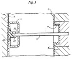
- Fig. 3 ein Schnitt durch den Beruhigungstopf in einer von der Darstellung in Fig. 2 abweichenden Ausbildung.
- Der Beruhigungstopf 3, in den gemäß dem Verfahren nach den Figuren 1 und 2 zuvor das Formstück 4 eingesetzt wurde, wird zwischen den beiden Backen 6 und 6' der Blasform von einer Stange 2 mit gabelförmigem Ende unterstützt. Darauf wird der aus einem Extruder austretende schlauchförmige Vorformling 1 über den Beruhigungstopf 3 herabgesenkt und der Haltedorn 5 von der Seite her in den Vorformling eingestochen und in eine Aussparung des Formstückes 4 eingeführt. Hierbei wird der Haltedorn 5 entweder mit dem an seinem vorderen Ende eingeschnittenen Gewinde in das Formstück 4 eingeschraubt oder mittels einer Vorrichtung 41, die einen in eine Ringnut des Haltedorn einrastenden gefederten Sperrkörper aufweist, in dem Formstück 4 festgehalten. Darauf wird die den Beruhigungstopf 3 unterstützende Stange 2 nach unten abgezogen, die Blasform 6, 6' geschlossen, der Vorformling 1 mittels Druckluft an die Blasform 6, 6' angedrückt und der Beruhigungstopf 3 mittels des Haltedorns 5 und des mit einem Kragen 42 gegen den Beruhigungstopf 3 anliegenden Formstücks 4 gegen den Backen 6 der Blasform angepreßt, so daß in den zwischen dem Rand der Bodenaussparung des Beruhigungstopfes 3 und dem Formstück 4 vorhandenen Ringspalt noch plastisches Material eindringt und den Beruhigungstopf 3 so zuverlässig verankert. Da bei dieser Art der Verankerung auf eine Schweißverbindung verzichtet werden kann, kann der Beruhigungstopf aus jedem beliebigen Material bestehen. Nun wird vor dem Öffnen der Blasform 6, 6' der Haltedorn 5 zurückgezogen, der Hohlkörper der Blasform entnommen, an der einen Gewindeansatz 7 aufweisenden Stelle aufgebohrt, so daß das Formstück aus dem Hohlkörper entfernt werden kann. Die dem Beruhigungstopf gegenüberliegende, mit einem Gewindeansatz versehene Öffnung dient vorteilhafterweise zum Anschluß des Gebers für die Tankinhaltsanzeigevorrichtung.
- Bei Verwendung eines Beruhigungstopfes gemäs Fig. 3 weist der Boden des Beruhigungstopfes hinterschnittene randoffene Aussparungen 31 auf, in die beim Anpressen des Beruhigungstopfes an die Seitenwand des noch plastischen Hohlkörpers 1 Kunststoff eindringt und so den Beruhigungstopf verankert. An der Bodeninnenseite ist ein Ansatz 32 mit einer Aussparung 33 vorgesehen, in die das freie Ende des Haltedorns 5 eingreift. Die Aussparung 33 ist vorteilhafterweise mehreckig ausgebildet, um den Beruhigungstopf mittels des Haltedorns 5 in die gewünschte Lage bringen zu können.
Claims (6)
Priority Applications (1)
| Application Number | Priority Date | Filing Date | Title |
|---|---|---|---|
| AT83108984T ATE43285T1 (de) | 1982-09-15 | 1983-09-12 | Verfahren zum herstellen eines mit oeffnungen versehenen hohlkoerpers aus thermoplastischem kunststoff. |
Applications Claiming Priority (2)
| Application Number | Priority Date | Filing Date | Title |
|---|---|---|---|
| DE3234180A DE3234180C2 (de) | 1982-09-15 | 1982-09-15 | Verfahren zum Herstellen eines Kraftstoffbehälters mit mindestens einem Beruhigungstopf und Vorrichtung zur Durchführung des Verfahrens |
| DE3234180 | 1982-09-15 |
Publications (3)
| Publication Number | Publication Date |
|---|---|
| EP0103832A2 EP0103832A2 (de) | 1984-03-28 |
| EP0103832A3 EP0103832A3 (en) | 1985-12-04 |
| EP0103832B1 true EP0103832B1 (de) | 1989-05-24 |
Family
ID=6173268
Family Applications (1)
| Application Number | Title | Priority Date | Filing Date |
|---|---|---|---|
| EP83108984A Expired EP0103832B1 (de) | 1982-09-15 | 1983-09-12 | Verfahren zum Herstellen eines mit Öffnungen versehenen Hohlkörpers aus thermoplastischem Kunststoff |
Country Status (3)
| Country | Link |
|---|---|
| EP (1) | EP0103832B1 (de) |
| AT (1) | ATE43285T1 (de) |
| DE (2) | DE3234180C2 (de) |
Cited By (1)
| Publication number | Priority date | Publication date | Assignee | Title |
|---|---|---|---|---|
| WO2021018732A1 (de) * | 2019-07-29 | 2021-02-04 | Kautex Textron Gmbh & Co. Kg | Verfahren zum herstellen eines betriebsstoffbehälters, formwerkzeug, betriebsstoffbehälter und kraftfahrzeug |
Families Citing this family (12)
| Publication number | Priority date | Publication date | Assignee | Title |
|---|---|---|---|---|
| DE3730488A1 (de) * | 1987-09-11 | 1989-03-23 | Rehau Ag & Co | Verfahren zur herstellung eines blasformkoerpers |
| IT1231336B (it) * | 1989-08-17 | 1991-11-28 | Sviluppo Settori Impiego Srl | Procedimento per la preparazione di corpi formati strutturali e termoisolanti e prodotti cosi' ottenuti |
| US5445783A (en) * | 1993-07-06 | 1995-08-29 | Ford Motor Company | Blow molding method |
| FR2873321B1 (fr) | 2004-07-23 | 2008-05-09 | Inergy Automotive Systems Res | Procede pour la fixation d'un accessoire dans un reservoir a carburant en matiere plastique |
| DE102006006469B4 (de) * | 2006-02-10 | 2018-02-22 | Kautex Textron Gmbh & Co. Kg | Verfahren zum Herstellen eines Kunststoff-Behälters |
| US9023264B2 (en) | 2006-07-03 | 2015-05-05 | Kautex Textron Gmbh & Co. Kg | Method for producing a container of thermoplastic material |
| US9346211B2 (en) | 2007-05-10 | 2016-05-24 | Plastic Omnium Advanced Innovation And Research | Process for manufacturing a fuel tank equipped with an internal accessory |
| FR2915923B1 (fr) | 2007-05-10 | 2009-07-10 | Inergy Automotive Systems Res | Procede de fabrication d'un reservoir a carburant muni d'un accessoire interne |
| DE102009030492B4 (de) | 2009-06-24 | 2023-06-15 | Kautex Maschinenbau Gmbh | Verfahren zur Herstellung eines Kunststoffartikels sowie Blasformwerkzeug |
| DE102009031441B4 (de) * | 2009-07-01 | 2012-06-28 | Kautex Maschinenbau Gmbh | Verfahren zur Herstellung eines Artikels aus thermoplastischem Kunststoff |
| ES2555547T3 (es) | 2010-12-03 | 2016-01-04 | Salflex Polymers Ltd. | Deflector de depósito de combustible desplegable y sistema de depósito de combustible |
| EP2946905B1 (de) * | 2014-05-23 | 2017-03-22 | Inergy Automotive Systems Research (Société Anonyme) | Verfahren zur Befestigung eines Zubehörteils in einem blasgeformten Kunststoffbehälter |
Family Cites Families (3)
| Publication number | Priority date | Publication date | Assignee | Title |
|---|---|---|---|---|
| DE1455496B2 (de) * | 1964-04-25 | 1974-01-24 | Kautex-Werke Reinhold Hagen Gmbh, 5300 Bonn-Holzlar | Mit einem Beruhigungstopf versehener Kraftstofftank für Fahrzeuge |
| US4396562A (en) * | 1978-07-28 | 1983-08-02 | Creaplast | Method of producing a hollow monobloc body by using a blowing process |
| DE3042926C2 (de) * | 1980-11-14 | 1984-06-20 | Elbatainer Kunststoff- Und Verpackungsgesellschaft Mbh, 7505 Ettlingen | Verfahren und Vorrichtung zur Herstellung eines Kraftstofftanks |
-
1982
- 1982-09-15 DE DE3234180A patent/DE3234180C2/de not_active Expired
-
1983
- 1983-09-12 EP EP83108984A patent/EP0103832B1/de not_active Expired
- 1983-09-12 AT AT83108984T patent/ATE43285T1/de not_active IP Right Cessation
- 1983-09-12 DE DE8383108984T patent/DE3379896D1/de not_active Expired
Cited By (1)
| Publication number | Priority date | Publication date | Assignee | Title |
|---|---|---|---|---|
| WO2021018732A1 (de) * | 2019-07-29 | 2021-02-04 | Kautex Textron Gmbh & Co. Kg | Verfahren zum herstellen eines betriebsstoffbehälters, formwerkzeug, betriebsstoffbehälter und kraftfahrzeug |
Also Published As
| Publication number | Publication date |
|---|---|
| DE3234180A1 (de) | 1984-03-15 |
| EP0103832A3 (en) | 1985-12-04 |
| ATE43285T1 (de) | 1989-06-15 |
| EP0103832A2 (de) | 1984-03-28 |
| DE3379896D1 (en) | 1989-06-29 |
| DE3234180C2 (de) | 1987-01-15 |
Similar Documents
| Publication | Publication Date | Title |
|---|---|---|
| EP0103832B1 (de) | Verfahren zum Herstellen eines mit Öffnungen versehenen Hohlkörpers aus thermoplastischem Kunststoff | |
| EP1981694B1 (de) | Verfahren zur herstellung eines kunststoff-hohlkörpers | |
| DE69117425T2 (de) | Verfahren zur herstellung einer henkelflasche | |
| DE102009015964A1 (de) | Druckbehälter-Rohling sowie Verfahren und Blasformstation zu seiner Herstellung | |
| DE3445542A1 (de) | Verfahren zur herstellung eines hermetisch dichten behaelters und fuelldorn dafuer | |
| DE102010032279B4 (de) | Verfahren zur Nietbefestigung eines Zubehörteils | |
| DE102009031441B4 (de) | Verfahren zur Herstellung eines Artikels aus thermoplastischem Kunststoff | |
| DE3042926C2 (de) | Verfahren und Vorrichtung zur Herstellung eines Kraftstofftanks | |
| EP0312725A2 (de) | Tropferflasche und Verfahren zu ihrer Herstellung | |
| DE3134602C2 (de) | Verfahren und Vorrichtung zur Herstellung einer Tube mit Verschlußkappe aus Kunststoff | |
| DE1299406B (de) | Verfahren und Vorrichtung zum Herstellen von Flaschen u. dgl. Hohl-koerpern aus warmformbaren Kunststoffen | |
| EP0085360A2 (de) | Abdichtelement | |
| DE3709426C2 (de) | ||
| DE3005931C2 (de) | Verfahren und Vorrichtung zum Herstellen eines insbesondere gefüllten und geschlossenen Behälters aus thermoplastischem Kunststoff und damit hergestellter Behälter | |
| DE1134820B (de) | Verfahren zum Befestigen eines Verschlusselementes in Behaeltern aus Kunststoff | |
| DE2356796A1 (de) | Hohlkoerper und verfahren zu dessen herstellung | |
| DE2131465C2 (de) | Flüssigkeitsgefüllter verschlossener Behälter aus flexiblem Kunststoff | |
| DE2222535C3 (de) | Verfahren und Vorrichtung zum Steuern der Einwärtsbewegung eines Stempels einer Blasform beim Herstellen eines Hohlkörpers | |
| DE19730800C2 (de) | Verfahren zum Herstellen einer Wärmflasche und danach hergestellte Wärmflasche | |
| DE1250104B (de) | ||
| DE102021130343A1 (de) | Blasverfahren mit eingesetztem Anschlussstück | |
| DE1479656B2 (de) | Verfahren und Vorrichtung zur Herstellung von hohlen Gegenständen aus thermoplastischem Material durch Aufweiten mittels eines Blasmediums | |
| DE1962438B2 (de) | Verfahren zum Füllen und dichten Verschließen von Druckmittelbehältern, insbesondere Flüssiggasbehältern, und Ventilverschluß | |
| DE8225986U1 (de) | Vorrichtung zum Herstellen eines aus Kunststoff bestehenden Hohlkörpers | |
| DE2558952C3 (de) | Verfahren zum Herstellen von Befestigungselementen und Vorrichtung zur Durchführung des Verfahrens |
Legal Events
| Date | Code | Title | Description |
|---|---|---|---|
| PUAI | Public reference made under article 153(3) epc to a published international application that has entered the european phase |
Free format text: ORIGINAL CODE: 0009012 |
|
| AK | Designated contracting states |
Designated state(s): AT DE FR IT |
|
| PUAL | Search report despatched |
Free format text: ORIGINAL CODE: 0009013 |
|
| RHK1 | Main classification (correction) |
Ipc: B29C 49/20 |
|
| AK | Designated contracting states |
Designated state(s): AT DE FR IT |
|
| 17P | Request for examination filed |
Effective date: 19860117 |
|
| 17Q | First examination report despatched |
Effective date: 19860822 |
|
| GRAA | (expected) grant |
Free format text: ORIGINAL CODE: 0009210 |
|
| AK | Designated contracting states |
Kind code of ref document: B1 Designated state(s): AT DE FR IT |
|
| REF | Corresponds to: |
Ref document number: 43285 Country of ref document: AT Date of ref document: 19890615 Kind code of ref document: T |
|
| REF | Corresponds to: |
Ref document number: 3379896 Country of ref document: DE Date of ref document: 19890629 |
|
| ITF | It: translation for a ep patent filed | ||
| ET | Fr: translation filed | ||
| PLBE | No opposition filed within time limit |
Free format text: ORIGINAL CODE: 0009261 |
|
| STAA | Information on the status of an ep patent application or granted ep patent |
Free format text: STATUS: NO OPPOSITION FILED WITHIN TIME LIMIT |
|
| 26N | No opposition filed | ||
| PGFP | Annual fee paid to national office [announced via postgrant information from national office to epo] |
Ref country code: AT Payment date: 19900808 Year of fee payment: 8 |
|
| PG25 | Lapsed in a contracting state [announced via postgrant information from national office to epo] |
Ref country code: AT Effective date: 19910912 |
|
| ITTA | It: last paid annual fee | ||
| PGFP | Annual fee paid to national office [announced via postgrant information from national office to epo] |
Ref country code: FR Payment date: 19961010 Year of fee payment: 14 |
|
| PG25 | Lapsed in a contracting state [announced via postgrant information from national office to epo] |
Ref country code: FR Free format text: THE PATENT HAS BEEN ANNULLED BY A DECISION OF A NATIONAL AUTHORITY Effective date: 19970930 |
|
| PGFP | Annual fee paid to national office [announced via postgrant information from national office to epo] |
Ref country code: DE Payment date: 19971018 Year of fee payment: 15 |
|
| REG | Reference to a national code |
Ref country code: FR Ref legal event code: ST |