EP0103838A2 - Cooling and heating device for spaces, particularly for vehicle cabins - Google Patents
Cooling and heating device for spaces, particularly for vehicle cabins Download PDFInfo
- Publication number
- EP0103838A2 EP0103838A2 EP83109010A EP83109010A EP0103838A2 EP 0103838 A2 EP0103838 A2 EP 0103838A2 EP 83109010 A EP83109010 A EP 83109010A EP 83109010 A EP83109010 A EP 83109010A EP 0103838 A2 EP0103838 A2 EP 0103838A2
- Authority
- EP
- European Patent Office
- Prior art keywords
- heater
- flap
- air
- cooling
- heating
- Prior art date
- Legal status (The legal status is an assumption and is not a legal conclusion. Google has not performed a legal analysis and makes no representation as to the accuracy of the status listed.)
- Withdrawn
Links
Images

Classifications
-
- B—PERFORMING OPERATIONS; TRANSPORTING
- B60—VEHICLES IN GENERAL
- B60H—ARRANGEMENTS OF HEATING, COOLING, VENTILATING OR OTHER AIR-TREATING DEVICES SPECIALLY ADAPTED FOR PASSENGER OR GOODS SPACES OF VEHICLES
- B60H1/00—Heating, cooling or ventilating devices
- B60H1/00357—Air-conditioning arrangements specially adapted for particular vehicles
- B60H1/00378—Air-conditioning arrangements specially adapted for particular vehicles for tractor or load vehicle cabins
-
- B—PERFORMING OPERATIONS; TRANSPORTING
- B60—VEHICLES IN GENERAL
- B60H—ARRANGEMENTS OF HEATING, COOLING, VENTILATING OR OTHER AIR-TREATING DEVICES SPECIALLY ADAPTED FOR PASSENGER OR GOODS SPACES OF VEHICLES
- B60H1/00—Heating, cooling or ventilating devices
- B60H1/00007—Combined heating, ventilating, or cooling devices
Definitions
- the invention relates to a cooling and heating device for rooms, in particular vehicle cabins, with a duct system through which air flows, in which a cooling part, a heater and an adjustable bypass member are provided, via which the air at least partially bypasses the heater or completely the heater can be run.
- a blower is provided, via which an air flow depending on the position of the bypass flap designed as a pivotable flap is fed to the cooling part in the form of a cooling coil or the heating, cooling part and Heating are arranged in separate housing parts, so that the air flow is guided into different channels, depending on whether the air has been heated or not.
- the air flow is divided so that the blowing effect is reduced without additional fans.
- This publication does not disclose whether the heating in this device always remains switched on.
- the object to be achieved with the invention is seen in ensuring a simple construction which can also make it possible, depending on the switch-on position of the heating, that at least part of the air flow not through the heating but not when the heating is not switched on is led past the heater.
- the heater is arranged directly behind the cooling part with respect to the flow direction of the air and / or the actuation for the heater and the bypass member are so positively connected to one another that the heater can only be fully heated when the bypass member is in a position in which the air is completely led through the heater.
- the cooling part which can be the evaporator of an air conditioning system, and the heating are arranged in a common housing duct, so that separate air passages for hot or cold air and thus also additional fans are not required.
- the forced control of the bypass element prevents heating of the heater when the temperature in the F does not require ahrzeugkabine, which is effected via a common ühlteil for K and heating operation in a simple manner.
- the bypass member is designed as a pivotable flap and the heater arranged in a housing is at a distance from a housing wall
- the flap in the area in which the heater is at a distance from the housing wall provided and connected to a heating valve via a linkage.
- the heater is provided according to the invention with an inlet line and has a flap which is inserted into the inlet line and can be pivoted from a closed position into an open position and is arranged on a pin, the pin being rotatably inserted into the inlet line and having an end projecting from the inlet line is provided, to which a boom is fixedly connected, which is articulated via a further boom with the flap on the heater.
- the arrangement is such that the flap of the heating valve is in its open position when the flap on the heater is in its closed position.
- the flap of the heating valve can expediently be pivoted from its open position into its closed position via a Bowden cable engaging the pin against the action of a spring.
- the cooling part comprises a casing wall spacing, and in this area hen another flap in front g ESE which is connected to the heating valve via a linkage.
- a vehicle cabin 11 shown in FIG. 1 can be equipped with an air conditioning and heating system.
- the vehicle cabin 11 is designed to be insulated and has an air intake system 13 in its lower region.
- the latter is provided with a channel 15 into which an inlet opening 19 for fresh air from outside the vehicle cabin and an inlet opening 21 for cabin air open. Both inlet openings 19 and 21 are provided with filters for filtering out foreign particles in the air.
- the channel 15 is formed in such a way that it forms a substantially longitudinally extending passage 23 which merges into a likewise longitudinally extending chamber 25 which is formed by a housing 27 and receives a cooling part which, as an evaporator 29, is not shown Air conditioning can be designed.
- the evaporator 29 itself is arranged at a distance from a side wall 33 of the housing 27 in the chamber 25 and is located in relation to the air direction in front of a heater 31, which is also arranged permanently in the chamber 25 and to one of the side walls 33 of the housing 27 has distance.
- a centrifugal blower 35 is also provided in the chamber 25, which has an inlet 37 and an outlet 39 which opens into an air duct 41.
- the heating is still with an on and an outlet line 43 and 47 are provided which are guided through the housing 27 and can be connected to an engine block, which is not shown in the drawing for the sake of simplicity, in order to be able to heat the heater via the coolant.
- a heating valve 45 in the inlet line 43 the flow of the coolant can be regulated according to the driver's wishes (less or stronger heating effect) or can be switched off entirely.
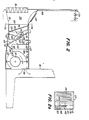
- the heating valve 45 is designed as a flap valve and is therefore provided with a rotatable pin 49 which penetrates the cross section of the inlet line 43 and on which a flap 51 which is adapted to the inside diameter of the inlet line and is adjustable from an open position shown in FIG. 2 to a closed position is fixed .
- a first boom 53 is fixedly arranged on the latter at its end protruding from the inlet line 43, which in turn is articulated to a second boom 55 via a pin 57.
- the end of the second arm 55 remote from the pin 57 extends up to approximately the bottom of the housing 27 and is articulated there at 61 to a flap 59 serving as a bypass member.
- the flap 59 is connected via a hinge 63 to the bottom of the heater 31 and designed so that in its position shown in FIG. 2 it bridges the free distance between the heater 31 and the housing wall 33 and thus closes this space, so that in this position, the air sucked in by the centrifugal fan 35 must pass through the heater 31.
- the flap 59 can be pivoted via the arm 55 into an open position, in which at least some of the air drawn in does not have to pass through the heater.
- the flaps 51 and 59 can be actuated together in such a way that when one flap is closed, the other is in their open position.
- the flaps can also assume a variety of intermediate positions. However which engages via a spring 65 one end to the pin 57 and the other end at 67 to the housing wall 33, the flaps are in their in Fig. 2 '. reproduced positions drawn.
- a Bowden cable 69 or the like is used to actuate the flaps 51 and 59, the wire of which also engages on the pin 57 and the one jacket end of which is firmly connected to a holder 71. The other end of the Bowden cable is connected to an actuator 73, which in turn is provided inside the cabin.
- filtered air enters through the inlet openings 19 and 21, the air entering through the inlet opening 21 possibly being air-conditioned.
- the air is sucked in by the centrifugal fan 35 and passed through the heater 31 or between the fins or tubes, as the heater valve 45 g in its open position and the flap 59 in its closed position by Fi. 2 are located.
- the heating valve 45 can assume a variety of positions, which range from the open position to the closed position or vice versa, the flap 59 taking corresponding positions in the reverse order. That is, when the heating valve 45 is fully open, the flap is in its fully closed position, in which all air is thus guided through the heating 31 and thus heated accordingly.
- the heating valve 45 if the heating valve 45 is in its fully closed position, the flap 59 takes its completely ge open position and a considerable flow of air is directed past the heater. Depending on how much the heater 31 is then heated, the air flow then still passed through the heater is hardly or not at all heated. In the intermediate positions, the air flow assumes corresponding intermediate temperatures.
- the evaporator can also be provided with a flap which can be actuated as a function of the heating valve and which, at least when the heating is fully switched on, leads a part of the air flow past the evaporator and is then no longer cooled.
Landscapes
- Physics & Mathematics (AREA)
- Thermal Sciences (AREA)
- Engineering & Computer Science (AREA)
- Mechanical Engineering (AREA)
- Air-Conditioning For Vehicles (AREA)
- Catching Or Destruction (AREA)
Applications Claiming Priority (2)
| Application Number | Priority Date | Filing Date | Title |
|---|---|---|---|
| US42067182A | 1982-09-21 | 1982-09-21 | |
| US420671 | 1999-10-19 |
Publications (2)
| Publication Number | Publication Date |
|---|---|
| EP0103838A2 true EP0103838A2 (fr) | 1984-03-28 |
| EP0103838A3 EP0103838A3 (fr) | 1984-10-10 |
Family
ID=23667397
Family Applications (1)
| Application Number | Title | Priority Date | Filing Date |
|---|---|---|---|
| EP83109010A Withdrawn EP0103838A3 (fr) | 1982-09-21 | 1983-09-13 | Cooling and heating device for spaces, particularly for vehicle cabins |
Country Status (3)
| Country | Link |
|---|---|
| EP (1) | EP0103838A3 (fr) |
| JP (1) | JPS5977919A (fr) |
| ES (1) | ES525751A0 (fr) |
Cited By (1)
| Publication number | Priority date | Publication date | Assignee | Title |
|---|---|---|---|---|
| DE3839131A1 (de) * | 1988-11-19 | 1990-05-23 | Daimler Benz Ag | Klimaanlage fuer fahrzeuge |
Family Cites Families (5)
| Publication number | Priority date | Publication date | Assignee | Title |
|---|---|---|---|---|
| GB819801A (en) * | 1955-04-01 | 1959-09-09 | Smith & Sons Ltd S | Improvements in or relating to heating and ventilating devices for vehicles |
| GB827073A (en) * | 1955-10-10 | 1960-02-03 | Smith & Sons Ltd S | Improvements in or relating to heating and or ventilating devices for vehicles |
| FR1213582A (fr) * | 1957-09-05 | 1960-04-01 | Smith & Sons Ltd S | Appareil de chauffage et de ventilation pour véhicules |
| US3555846A (en) * | 1968-12-13 | 1971-01-19 | Stolper Ind Inc | Air-conditioned vehicle cab |
| JPS5848890Y2 (ja) * | 1979-10-16 | 1983-11-08 | トヨタ自動車株式会社 | 車輛用空気調和装置 |
-
1983
- 1983-09-13 EP EP83109010A patent/EP0103838A3/fr not_active Withdrawn
- 1983-09-20 ES ES525751A patent/ES525751A0/es active Granted
- 1983-09-21 JP JP17514883A patent/JPS5977919A/ja active Pending
Cited By (1)
| Publication number | Priority date | Publication date | Assignee | Title |
|---|---|---|---|---|
| DE3839131A1 (de) * | 1988-11-19 | 1990-05-23 | Daimler Benz Ag | Klimaanlage fuer fahrzeuge |
Also Published As
| Publication number | Publication date |
|---|---|
| EP0103838A3 (fr) | 1984-10-10 |
| JPS5977919A (ja) | 1984-05-04 |
| ES8406314A1 (es) | 1984-08-01 |
| ES525751A0 (es) | 1984-08-01 |
Similar Documents
| Publication | Publication Date | Title |
|---|---|---|
| DE60223437T2 (de) | Fahrzeugklimaanlage | |
| DE3232957C2 (fr) | ||
| EP1134102A2 (fr) | Installation de chauffage ou de climatisation | |
| EP0354163B1 (fr) | Dispositif pour chauffer l'intérieur d'un véhicule automobile | |
| DE3010485A1 (de) | Kuehleranordnung fuer kraftfahrzeuge | |
| EP0183937B1 (fr) | Dispositif pour filtrer un courant d'air d'alimentation, en particulier pour des véhicules automobiles | |
| DE3608524C2 (fr) | ||
| DE3923307C2 (fr) | ||
| DE19919975C1 (de) | Klimaanlage für eine Fahrgastzelle eines Fahrzeugs | |
| DE102015103393A1 (de) | Kraftfahrzeug mit einstellbarem Wärmetauscherabluftpfad | |
| DE19816329C2 (de) | Heizungs- und Klimaanlage | |
| EP0845375B1 (fr) | Dispositif de chauffage ou de climatisation d'un véhicule | |
| DE3344562C2 (fr) | ||
| DE102005024444A1 (de) | Kühlsystem | |
| DE3121650C2 (de) | Kühlvorrichtung für eine ein Kraftfahrzeug antreibende Brennkraftmaschine | |
| DE2836800A1 (de) | Heiz- und belueftungsvorrichtung fuer ein fahrzeug | |
| EP0103838A2 (fr) | Cooling and heating device for spaces, particularly for vehicle cabins | |
| EP0841202B1 (fr) | Installation de chauffage ou de climatisation | |
| WO2010146553A1 (fr) | Dispositif de protection antigel d'un dispositif d'échange d'air à récupération et procédé permettant de faire fonctionner le dispositif | |
| DE3335769A1 (de) | Heiz- und/oder klimaanlage fuer kraftfahrzeuge | |
| DE2101914C2 (de) | Klimaanlage für Fahrzeuge | |
| DE19545029C1 (de) | Belüftungsvorrichtung für Fahrzeuge | |
| EP1646519B1 (fr) | Systeme d'encastrement destine a une climatisation de vehicule | |
| DE3048195C2 (de) | Heizungs-, Belüftungs- oder Klimaanlage für Kraftfahrzeuge | |
| DE10011932C1 (de) | Einrichtung zum Zuführen von Luft in eine Fahrgastzelle eines Fahrzeugs |
Legal Events
| Date | Code | Title | Description |
|---|---|---|---|
| PUAI | Public reference made under article 153(3) epc to a published international application that has entered the european phase |
Free format text: ORIGINAL CODE: 0009012 |
|
| AK | Designated contracting states |
Designated state(s): DE FR GB |
|
| PUAL | Search report despatched |
Free format text: ORIGINAL CODE: 0009013 |
|
| AK | Designated contracting states |
Designated state(s): DE FR GB |
|
| EL | Fr: translation of claims filed | ||
| STAA | Information on the status of an ep patent application or granted ep patent |
Free format text: STATUS: THE APPLICATION IS DEEMED TO BE WITHDRAWN |
|
| 18D | Application deemed to be withdrawn |
Effective date: 19850611 |
|
| RIN1 | Information on inventor provided before grant (corrected) |
Inventor name: SISK, ROBERT MICHAEL Inventor name: LEWIS, WILLIAM LEE |