EP0103870A2 - Kombinierte Herstellung von Aethern und Alkylaten - Google Patents
Kombinierte Herstellung von Aethern und Alkylaten Download PDFInfo
- Publication number
- EP0103870A2 EP0103870A2 EP83109201A EP83109201A EP0103870A2 EP 0103870 A2 EP0103870 A2 EP 0103870A2 EP 83109201 A EP83109201 A EP 83109201A EP 83109201 A EP83109201 A EP 83109201A EP 0103870 A2 EP0103870 A2 EP 0103870A2
- Authority
- EP
- European Patent Office
- Prior art keywords
- alcohol
- distillation
- zone
- overhead
- stream
- Prior art date
- Legal status (The legal status is an assumption and is not a legal conclusion. Google has not performed a legal analysis and makes no representation as to the accuracy of the status listed.)
- Granted
Links
Images

Classifications
-
- C—CHEMISTRY; METALLURGY
- C07—ORGANIC CHEMISTRY
- C07C—ACYCLIC OR CARBOCYCLIC COMPOUNDS
- C07C41/00—Preparation of ethers; Preparation of compounds having groups, groups or groups
- C07C41/01—Preparation of ethers
- C07C41/05—Preparation of ethers by addition of compounds to unsaturated compounds
- C07C41/06—Preparation of ethers by addition of compounds to unsaturated compounds by addition of organic compounds only
-
- C—CHEMISTRY; METALLURGY
- C07—ORGANIC CHEMISTRY
- C07C—ACYCLIC OR CARBOCYCLIC COMPOUNDS
- C07C29/00—Preparation of compounds having hydroxy or O-metal groups bound to a carbon atom not belonging to a six-membered aromatic ring
- C07C29/74—Separation; Purification; Use of additives, e.g. for stabilisation
- C07C29/76—Separation; Purification; Use of additives, e.g. for stabilisation by physical treatment
- C07C29/80—Separation; Purification; Use of additives, e.g. for stabilisation by physical treatment by distillation
-
- C—CHEMISTRY; METALLURGY
- C07—ORGANIC CHEMISTRY
- C07C—ACYCLIC OR CARBOCYCLIC COMPOUNDS
- C07C9/00—Aliphatic saturated hydrocarbons
- C07C9/14—Aliphatic saturated hydrocarbons with five to fifteen carbon atoms
- C07C9/16—Branched-chain hydrocarbons
Definitions
- the present invention relates generally to the processing of alcohol to remove undesirable contaminants therefrom.
- the invention relates to a combined process for the production of ether and alkylate wherein alcohol is processed to remove undesirable contaminants therefrom.
- the invention relates to a system for controlling the removal of undesirable contaminants from alcohol in a combined process for the production of ether and alkylate.
- MTBE methyltertiarybutyl ether
- the combination process of ether formation and alkylation outlined above has the disadvantage that the olefin stream coming from the ether production may contain materials which are either harmful to the alkylation reaction as such or which tend to be released in the fractionation of the alkylation product in gaseous form, building up pressure and requiring venting, thus removing therewith, for instance, HF and/or propane, which are lost from the operation.
- An additional disadvantage of the above-described combination process is that the source of liquid methanol and even the method of handling liquid methanol for storage results in the methanol having dissolved therein oxygen and nitrogen, as from the air.
- Purchased methanol from a typical source can have up to about 88 parts per million by weight of oxygen and about 186 parts per million by weight of nitrogen (at 760mm Hg and 20°C) contained therein.
- Other contaminants or inerts that can be present are hydrogen, methane, ethane, ethylene, carbon dioxide, carbon monoxide, fuel gas, and/or materials that give undesirable reactions in the alkylation unit or are not condensed in the alkylation unit depropanizer accumulator.
- the isobutylene-containing hydrocarbon feedstock also contains other olefins, such as butene-1, cis-butene-2 and trans-butene-2, along with normal butane and isobutane.
- the feed may also contain propane, propylene, isopentane, normal pentane, and amylenes.
- the unconverted or unreacted linear butylenes are excellent feed components for the HF alkylation of isobutane to produce high octane gasoline.
- Another object of this invention is to provide a combined process for the production of ether and alkylate with reduced risk of losses of materials from the alkylation unit caused by undesirable materials entering the alkylation unit from the ether and/or from a source of alcohol.
- a further object of this invention is to provide a combined ether forming and alkylate forming process which renders the ether unit and the alkylation unit even more compatible.
- Yet another object of this invention is to provide a combined either forming and alkylate forming process of increased efficiency of operation.
- the alcohol reactant preferably methanol for the manufacture of ether, preferably MTBE, before being charged to the ether forming unit, is processed for the removal of light gases, such as oxygen and nitrogen, e.g., as from air, by the process of my invention which includes subjecting the raw alcohol, preferably methanol, containing undesired at least one of oxygen, nitrogen, methane, fuel gas, ethane, hydrogen, and ethylene to a preliminary stripping operation.
- substantially all the undesired at least one of oxygen, nitrogen, methane, fuel gas, ethane, hydrogen, and ethylene is removed from the alcohol, and a purified alcohol is recovered which can be charged to the ether forming unit, and the recovered straight chain butenes from the ether forming unit can then be charged to the HF alkylation unit without the at least one of oxygen, nitrogen, methane, fuel gas, ethane, hydrogen, and ethylene also referred to as "contaminants" and/or "inerts", pressuring up the depropanizer accumulator of the alkylation unit.
- substantially no venting of the depropanizer overhead accumulator is required and the desired savings of HF and propane is realized because of the pretreatment of the raw alcohol, e.g., methanol.
- the present invention improves a process for the production of both an ether and an alkylate.
- This process comprises contacting olefins and an alcohol to form a first reaction mixture comprising ether, alcohol and a portion of the the olefins. From this first reaction mixture ether is recovered as a first product of the process. In the ether forming unit one or more liquids are accumulated in one or more vessels for later use in the ether forming reaction. An olefin-containing stream is separated from the above-mentioned first reaction mixture.
- This olefin-containing stream, or at least a portion thereof, is contacted with an isoparaffin in the presence of an HF alkylation catalyst under HF alkylation conditions to form a second reaction mixture comprising alkylate.
- This alkylate is then recovered from the second reaction mixture as a second product of the combination process.
- This alkylate is generally recovered as a bottoms stream from a fractionation zone in which at least a portion of the second reaction mixture is fractionated.
- the fractionation zone is provided with an overhead accumulator in which the cooled and condensed overhead effluent from the fractionation zone is accumulated.
- a feed stream of a mixture containing alcohol and at least one of oxygen, nitrogen, methane, fuel gas, ethane, hydrogen, and ethylene is distilled in a first distillation zone thereby forming a first distillation overhead containing a first portion of the alcohol and the at least one of oxygen, nitrogen, methane, fuel gas, ethane, hydrogen, as well as a first distillation bottoms containing a second portion of the alcohol.
- At least a portion of the first distillation overhead containing the alcohol and the at least one of oxygen, nitrogen, methane, fuel gas, ethane, hydrogen, and ethylene is passed through a condensing zone forming a liquid phase and a gas phase in a phase separation zone.
- the separated liquid alcohol phase at least in part is returned to the first distillation zone, and the gaseous at least one of oxygen, nitrogen, methane, fuel gas, ethane, hydrogen, and ethylene phase is vented to atmosphere, flare, or other suitable disposal.
- the first distillation bottoms are recovered and supplied for use in the previously mentioned step of contacting olefins and an alcohol to form a first reaction mixture comprising ether, alcohol and a portion of the olefins.
- the alcohol employed is preferably methanol and the tertiary olefin is isobutylene, and the ether produced is preferably MTBE.
- the ether forming reaction of the combination process of this invention is known in the art both generally and in many of its details. Reference is made to U.S. Patent No. 3,846,088 in which such an ether production process, particularly for the production of MTBE is described.
- the present invention is applicable to a variety of ether forming units.
- the ether forming reaction is carried out by contacting alkyl alcohols having one to three carbon atoms, preferably methanol, with monoolefins having four to six carbon atoms under ether forming conditions in the presence of an ether forming catalyst.
- tertiary olefins having four or five carbon atoms and containing a tertiary carbon atom, such as, for example isobutylene and isoamylenes (2 methyl butene-1, 2 methyl butene-2) are used in the ether forming reaction.
- Typical ether forming catalysts include commercially available "Amberlyst 15", “Dowex 50” and “Nalcite HCR”.
- Ether forming reaction conditions and catalysts are well known in the art and are disclosed, for instance, in U.S. Patent 3,846,088, the disclosure of which is herewith incorporated by reference.
- the olefins useful in HF alkylation reactions, and particularly in the combination process of this invention are olefins having three to five carbon atoms.
- the isoparaffins used for the alkylation reaction are generally isoparaffins having four to six carbon atoms, isobutane being particularly preferred.
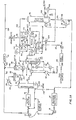
- An ether reactor 10 preferably an MTBE reactor is supplied with a stream comprising olefins, particularly isobutylene, from a suitable source of olefins by means of a pump 12.
- Process alcohol preferably methanol, is conveyed to the reactor 10 from an alcohol storage drum 14 by means of a pump 16.
- the olefins including at least one tertiary olefin, e.g., isobutylene and methanol are contacted in the reactor 10 under suitable ether reaction conditions to form a reaction mixture which is withdrawn from the reactor 10 via conduit 18.
- This reaction mixture comprises the ether formed, unreacted olefins and unreacted alcohol.
- the ether reaction mixture is directed from the conduit 18 into a fractionator 20 wherein the reaction mixture is fractionated and the ether is withdrawn from the fractionator 20 via conduit 22 as a first product of the process.
- An overhead stream leaves the fractionator 20 via conduit 24 and comprises unreacted olefins and methanol.
- This gaseous overhead stream is cooled by a suitable indirect heat exchanger 26 and the thereby condensed liquid is accumulated in an accumulator 28.
- a portion of the accumulated liquid is withdrawn from the accumulator 28 and is reintroduced by means of a pump 30 and conduit 32 into the fractionator 20 as a reflux stream.
- the remaining or yield portion of the accumulated liquid is passed from the accumulator 28 via conduit 34 to an alcohol washing column 36 into which water is introduced via conduit 38.
- a stream comprising mainly isobutane and the unreacted olefins and being substantially free of alcohol leaves the alcohol washing column 36 via conduit 40.
- This olefin containing stream is combined with another olefin containing stream passing from the pump 12 via conduit 42 (by-pass around MTBE Reactor 10) and this combined stream passes via conduit 44 to a suitable dryer 46 wherein any water contained therein from the alcohol washing column 36 is removed.
- Wet alcohol leaves the alcohol washing column 36 via conduit 48 and is introduced into distillation means in the form of an alcohol fractionator 50.
- Alcohol preferably methanol
- Alcohol containing a small amount of water leaves the alcohol fractionator 50 as an overhead stream via conduit 52.
- At least a portion of this alcohol containing a small amount of water alcohol is passed as vapor via conduits 54 and 56 to a cooler 58, and the thus condensed alcohol is passed from the cooler 58 via 3-way valve 60 to a separating zone, preferably in the form of an alcohol accumulator 62, where liquid alcohol, in this example methanol, is accumulated.
- a conduit 64 interconnects conduit 54 and the 3-way valve 60 to provide a bypass for the essentially water free alcohol vapor around the cooler 58 to the accumulator 62.
- Light gaseous contaminants and/or inerts for example at least one of oxygen, nitrogen, methane, fuel gas, ethane, hydrogen and ethylene are vented from the accumulator 62 via conduit 66 and a suitable cooler 68 interposed therein allowing venting of contaminants and/or inerts to the atmosphere or to a suitable flare for combustion prior to release to the atmosphere.
- the cooler 68 functions to condense any alcohol vapor vented from the accumulator 62 to prevent alcohol loss.
- a portion of the accumulated alcohol in the alcohol accumulator 62 is passed via conduit 70 and pump 72 to the alcohol fractionator 50 as a reflux stream.
- the remaining or yield portion of the alcohol accumulated in the alcohol accumulator 62 is passed via conduit 70, pump 72 and conduit 74 to a suitable distillation zone preferably in the form of an alcohol stripper column 76.
- Water is withdrawn from the bottom of the alcohol fractionator 50 via conduit 78 and indirect heat exchangers 80 and 82 interposed in conduit 78 for recovering heat from the water. This water in part can be recycled to conduit 38 by a suitable conduit (not shown) as a portion of the wash water for removing the alcohol from the stream comprising unreacted olefins and alcohol.
- Flow of the water through the conduit 78 is preferably controlled by suitable flow control means 84 interposed in the conduit 78 responsive to a suitable level controller 86 which senses the level of liquid water in the lower portion of the alcohol fractionator 50, and regulates the flow of the water through the conduit 78 such that the water level within the alcohol fractionator 50 is maintained within a suitable range.
- Raw alcohol in this example methanol
- a suitable source of raw alcohol into a suitable alcohol storage vessel 88.
- Raw alcohol from the alcohol storage vessel 88 is conveyed to the alcohol stripper column 76 via a pump 90, a conduit 92 and previously described conduit 74.
- the raw alcohol from the alcohol storage vessel is combined with the yield portion of the alcohol from the alcohol accumulator 62 at the juncture of the conduits 74 and 92, and the resulting combined alcohol stream is introduced into the alcohol stripper column 76.
- An alcohol distillation bottoms stream of liquid alcohol is passed from the lower end of the alcohol stripper column 76 to the alcohol storage drum 14 via conduit 94 and a suitable indirect heat exchanger 96 interposed in the conduit 94 to provide cooling of the liquid alcohol and heat recovery.
- the flow of liquid alcohol through conduit 94 is regulated by suitable flow control means 98 operatively related to a suitable level controller 100 in the lower portion of the alcohol stripper column 76, whereby the flow of liquid alcohol through the conduit 94 is constantly adjusted to maintain the level of liquid alcohol in the lower portion of the column 76 within a predetermined range as sensed by the level controller 100.
- a distillation overhead vapor stream containing a portion of the alcohol fed into the alcohol stripper column 76, as well as light gaseous contaminants and/or inerts, such as, for example, at least one of oxygen, nitrogen, methane, fuel gas, ethane, hydrogen, and ethylene is passed from the upper end of the alcohol stripper column 76 via conduit 102 to the juncture of previously described conduits 54 and 56.
- the distillation overhead stream from the alcohol stripper column 76 is combined with the alcohol overhead stream from the alcohol fractionator 50 and is conducted through the previously described cooler 58 and 3-way valve 60 into the alcohol accumulator 62.
- Suitable flow control means 104 having a predetermined set point, is interposed in conduit 74 intermediate conduit 92 and the alcohol stripper column 76.
- the flow control means 104 is operatively connected by suitable means to suitable flow control means 106 interposed in a steam supply line 108 which supplies steam to the lower end of the alcohol stripper column 76 to thereby control the heat input into the alcohol stripper column 76 to thus control the operation of the alcohol stripper column 76 in a predetermined manner.
- a suitable pressure controller 110 is operatively connected to the alcohol accumulator 62 to monitor the pressure therein.
- Pressure controller 110 is operatively connected by suitable means to the 3-way valve 60 and a control valve 112 interposed in conduit 66 whereby the valves 60 and 112 are automatically actuated to maintain the pressure in the alcohol accumulator 62 at a predetermined set point.
- a suitable analyzer 114 is connected in fluid flow communication with the conduit 52 to monitor the alcohol content of the overhead passing from the alcohol fractionator 50.
- the analyzer 114 is operatively connected by suitable means to suitable flow control means 116 interposed in conduit 70 intermediate the pump 72 and the alcohol fractionator 50 whereby the flow of the reflux stream to the alcohol fractionator 50 is increased in response to the sensing by the analyzer 114 of the presence of too little alcohol (too much water) in the overhead from the alcohol fractionator 50 to thereby prevent the removal of excessive water in the overhead.
- Suitable flow control means 118 are interposed in the conduit 74 intermediate conduits 70 and 92, are operatively connected by suitable means to a level controller 120, operatively related to the alcohol accumulator 62 and responsive to the level of liquid alcohol therein, for controlling the flow of liquid alcohol through the conduit 74 in response to signals from the level controller 120 to thereby maintain the liquid level within the accumulator 62 within a predetermined range.
- An olefin feedstream comprising dried olefins, (including isobutane and normal butane) from the dryer 46 is introduced into an alkylation reactor 122 via conduits 124 and 126.
- an isoparaffin-containing stream preferably an isobutane-containing stream, from a suitable isoparaffin source via conduits 128, 130 and 126.
- the liquid hydrocarbon phase is passed from the upper portion of the alkylation reactor to a fractionator 132 via conduit 134, pump 136 and a suitable heater 138 interposed in conduit 13 4.
- An alkylate stream is withdrawn from the bottom of the fractionator 13 2 via conduit 140.
- a paraffin vapor stream is withdrawn from the fractionator 132 via conduit 142.
- Isobutane liquid is withdrawn from the fractionator 132 via conduit 144 and is recycled to the HF alkylation reactor 122 via conduit 144 and conduits 130 and 126, and the overhead vapor stream comprising propane vapor and HF vapor is withdrawn from the upper end of the fractionator 132 via conduit 146 and is passed to an overhead accumulator 148 via conduit 150 and a suitable cooler-condenser 152 interposed in conduit 150.
- a portion of the liquid phase in the accumulator 148 is withdrawn via conduit 154 and is passed to the upper end of the fractionator 132 as a reflux stream via pump 156 interposed in conduit 154.
- the yield portion of the liquid phase is withdrawn from conduit 154 downstream of the pump 156 and is passed via conduit 158 to a stripper 160.
- Liquid HF is withdrawn from a downwardly extending leg of the overhead accumulator 148 via conduit 162, for recycle to the alkylation reactor by suitable conduit means (not shown).
- Liquid propane is withdrawn as a bottoms stream from the lower end of the stripper 160 via conduit 164.
- Propane vapor and HF vapor are passed from the upper end of the stripper 160 as an overhead stream and are recycled to the overhead accumulator 148 via a conduit 166 as well as conduit 150 and cooler-condenser 152.
- the gaseous phase therein can be vented to the atmosphere or to a suitable flare via conduit 168 and suitable normally closed valve 170 interposed in conduit 168.
- the HF alkylation reactor 122 comprises an alkylation reaction zone 172 in which the isobutane feed from stream conduit 126 is alkylated with the olefins from the dryer 46 in the presence of HF catalyst.
- the HF alkylation reactor 122 further includes a phase separator zone 174 in which the liquid hydrocarbon phase is separated from the liquid HF phase, with the liquid hydrocarbon phase passing from the phase separator zone 174 in the upper portion of the alkylation reactor 122 via the previously mentioned conduit 134, and with the liquid HF phase passing from the bottom of the phase separator zone 174 as a bottoms stream via conduit 176, and the thus separated liquid HF is recycled to the alkylation reaction zone 172 via cooler 177.
- the alcohol stripper column 76 it is presently preferred to operate the alcohol stripper column 76 such that from about 5 to about 30 volume percent of the alcohol stream, in this example methanol, preferably about 10 volume percent of the alcohol stream, along with at least one of oxygen, nitrogen, methane, fuel gas, ethane, hydrogen, and ethylene, is taken from the alcohol stripper column 76 as overhead through conduit 102.
- a typical distillation column for use as the alcohol stripper column 76 is provided with from about 10 to about 20 bubble trays.
- Typical operating conditions for the alcohol stripper portion of above-described system are as listed in the following table.
- conduit 178 which provides means for bypassing purified alcohol, in this case methanol, from the alcohol stripper column 76 and conduit 94 around the alcohol storage drum 14 to be directly introduced into the reactor 10 along with the tertiary olefin-containing feed stream.
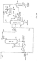
- FIG. 2 there is illustrated an alternate form of alcohol purification system for use in the combined ether and alkylate production system of the present invention.
- the system illustrated in FIG. 2 directs raw alcohol, in this case methanol, from the alcohol storage vessel 88 to the upper end portion of a distillation zone, preferably in the form of a suitable alcohol stripper column 76, via conduit 180 and a suitable pump 90 interposed therein.
- the purified liquid alcohol bottoms product is directed from the bottom of the column 76 via conduit 94 and indirect heat exchanger 96 to the alcohol storage drum 14.
- the indirect heat exchanger 96 provides means for preheating the raw alcohol stream passing through conduit 180 to the column 76.
- the vaporous overhead from the column 76 comprising alcohol, in this case methanol, and various contaminants and/or inerts, such as at least one of oxygen, nitrogen, methane, fuel gas, ethane, hydrogen, and ethylene, is conveyed from the top of the column 76 via conduits 102, 54 and 56, cooler-condenser 58 and 3-way valve 60 to a separating zone, preferably in the form of an alcohol accumulator 62.
- Conduit 64 provides vapor bypass fluid communication between conduit 102 and the 3-way valve 60.
- Bypass of the gaseous overhead from the stripper column 76 is controlled by the 3-way valve 60 in response to a suitable temperature controller 182 which is operatively connected to the valve 60 and controls its operation in response to the temperature sensed within the accumulator 62.
- the liquid phase within the accumulator 62 is passed therefrom to the upper end portion of the stripper column 76 as a reflux stream via conduit 184 and a suitable pump 186 interposed therein. Preferably all of the liquid phase from the accumulator 62 is used for this reflux stream.
- the flow rate of the reflux stream through conduit 184 is controlled by suitable operatively connected flow control means 188 and 190 in response to the flow rate of raw alcohol feed to the column 76 through conduit 180.
- the gaseous phase within the accumulator 62 comprising the various contaminants and/or inerts previously contained within the raw alcohol, for example, oxygen and/or nitrogen, is vented from the accumulator 62 via conduit 66 either to the atmosphere or to a suitable flare.
- Control of flow through the conduit 66 is provided by a suitable pressure controller 192 comprising control valve means interposed in the conduit 66 and responsive to the pressure within the accumulator 62.
- Reboil heat is provided to the lower portion of the alcohol stripper column 76 from the source of steam through conduit 108.
- Reboil heat input to the column 76 is controlled by means of suitable flow control means 194 comprising valve means interposed in conduit 108 and operatively connected to a suitable level control 196 on the accumulator 62 which controls steam flow to the column 76 in response to a liquid level sensed within the accumulator 62.
- the flow rate of purified liquid alcohol from the bottom of the alcohol stripper column 76 is controlled by a suitable flow control valve interposed in the conduit 94 and operatively connected to a suitable level.controller 198 which senses the liquid level within the lower end portion of the column 76 and controls the liquid flow in response to th liquid level within a predetermined range.
- the alcohol storage drum is preferably provided with pressure relief means in the form of a vent conduit 200 with suitable valve means interposed therein and operatively connected to a suitable pressure controller 202 which controls actuation of the valve means in response to the pressure sensed within the alcohol storage drum 14 so that the storage drum 14 is vented to the atmosphere or to a suitable flare when the pressure within the drum 14 exceeds a predetermined value.
- Typical operating conditions for the system illustrated in FIG 2 are identical to the operating conditions listed above for the system illustrated in FIGS. lA and 1B.
Landscapes
- Chemical & Material Sciences (AREA)
- Organic Chemistry (AREA)
- Engineering & Computer Science (AREA)
- Oil, Petroleum & Natural Gas (AREA)
- Organic Low-Molecular-Weight Compounds And Preparation Thereof (AREA)
Priority Applications (1)
| Application Number | Priority Date | Filing Date | Title |
|---|---|---|---|
| AT83109201T ATE31055T1 (de) | 1982-09-20 | 1983-09-16 | Kombinierte herstellung von aethern und alkylaten. |
Applications Claiming Priority (2)
| Application Number | Priority Date | Filing Date | Title |
|---|---|---|---|
| US42043582A | 1982-09-20 | 1982-09-20 | |
| US420435 | 1989-10-12 |
Publications (3)
| Publication Number | Publication Date |
|---|---|
| EP0103870A2 true EP0103870A2 (de) | 1984-03-28 |
| EP0103870A3 EP0103870A3 (en) | 1985-07-03 |
| EP0103870B1 EP0103870B1 (de) | 1987-11-25 |
Family
ID=23666457
Family Applications (1)
| Application Number | Title | Priority Date | Filing Date |
|---|---|---|---|
| EP83109201A Expired EP0103870B1 (de) | 1982-09-20 | 1983-09-16 | Kombinierte Herstellung von Aethern und Alkylaten |
Country Status (4)
| Country | Link |
|---|---|
| EP (1) | EP0103870B1 (de) |
| AT (1) | ATE31055T1 (de) |
| CA (1) | CA1259337A (de) |
| DE (1) | DE3374682D1 (de) |
Cited By (5)
| Publication number | Priority date | Publication date | Assignee | Title |
|---|---|---|---|---|
| EP0179456A3 (en) * | 1984-10-24 | 1987-03-18 | Phillips Petroleum Company | Combination alkylation-etherification process |
| WO1987007260A1 (en) * | 1986-05-27 | 1987-12-03 | Snamprogetti S.P.A. | Process for the synthesis of methyl-tert-alkyl ethers with suppression of corrosion |
| WO1987007259A1 (en) * | 1986-05-27 | 1987-12-03 | Snamprogetti S.P.A. | Process for preparing alkyl-tert-butyl ethers |
| US4761504A (en) * | 1986-12-29 | 1988-08-02 | Uop Inc. | Integrated process for high octane alkylation and etherification |
| EP0474188A3 (en) * | 1990-09-04 | 1994-08-24 | Phillips Petroleum Co | Methyl-tertiaryalkyl ether production |
Family Cites Families (1)
| Publication number | Priority date | Publication date | Assignee | Title |
|---|---|---|---|---|
| US4218569A (en) * | 1978-03-14 | 1980-08-19 | Gulf Canada Limited | Method for processing etherified light hydrocarbon mixtures to remove methanol |
-
1983
- 1983-05-31 CA CA000429287A patent/CA1259337A/en not_active Expired
- 1983-09-16 DE DE8383109201T patent/DE3374682D1/de not_active Expired
- 1983-09-16 EP EP83109201A patent/EP0103870B1/de not_active Expired
- 1983-09-16 AT AT83109201T patent/ATE31055T1/de not_active IP Right Cessation
Cited By (5)
| Publication number | Priority date | Publication date | Assignee | Title |
|---|---|---|---|---|
| EP0179456A3 (en) * | 1984-10-24 | 1987-03-18 | Phillips Petroleum Company | Combination alkylation-etherification process |
| WO1987007260A1 (en) * | 1986-05-27 | 1987-12-03 | Snamprogetti S.P.A. | Process for the synthesis of methyl-tert-alkyl ethers with suppression of corrosion |
| WO1987007259A1 (en) * | 1986-05-27 | 1987-12-03 | Snamprogetti S.P.A. | Process for preparing alkyl-tert-butyl ethers |
| US4761504A (en) * | 1986-12-29 | 1988-08-02 | Uop Inc. | Integrated process for high octane alkylation and etherification |
| EP0474188A3 (en) * | 1990-09-04 | 1994-08-24 | Phillips Petroleum Co | Methyl-tertiaryalkyl ether production |
Also Published As
| Publication number | Publication date |
|---|---|
| EP0103870B1 (de) | 1987-11-25 |
| DE3374682D1 (en) | 1988-01-07 |
| ATE31055T1 (de) | 1987-12-15 |
| CA1259337A (en) | 1989-09-12 |
| EP0103870A3 (en) | 1985-07-03 |
Similar Documents
| Publication | Publication Date | Title |
|---|---|---|
| CA1292249C (en) | Process containing hf alkylation and selective hydrogenation | |
| JPS6366288A (ja) | メタノ−ルをアルキルエ−テルに変換する改良された方法 | |
| US4503265A (en) | Process for the production of methyl tert.-butyl ether (MTBE) and of hydrocarbon raffinates substantially freed from i-butene and from methanol | |
| US3763022A (en) | Condensing fractionator sidestream vapor as reboiler heat source | |
| JPS6366287A (ja) | 酸素含有化合物を重質液体炭化水素に転化する連続接触方法及び制御システム | |
| EP0179456B1 (de) | Kombiniertes Alkylierungsveretherungsverfahren | |
| US5986148A (en) | Di-isopropyl ether synthesis and dry product recovery | |
| US4510336A (en) | Transetherification method | |
| EP0103870B1 (de) | Kombinierte Herstellung von Aethern und Alkylaten | |
| US4513165A (en) | Alkylation process | |
| US4479018A (en) | Combined ether and alkylate production | |
| AU676893B2 (en) | Di-isopropyl ether production | |
| JP2961052B2 (ja) | 炭化水素のアルキル化方法 | |
| CA1240341A (en) | Hf alkylation with product recycle employing two reactors | |
| US5113024A (en) | Process for product separation in the production of di-isopropyl ether | |
| US12448342B2 (en) | Process for obtaining isobutene from a C4-hydrocarbon mixture | |
| US4115471A (en) | Method for separating the product effluent of an alkylation process | |
| US5154801A (en) | Advances in product separation in dipe process | |
| US4761504A (en) | Integrated process for high octane alkylation and etherification | |
| US4180526A (en) | Alkylation process utilizing side draw vapor as heat source in isostripper | |
| US2382067A (en) | Alkylation | |
| KR20230154945A (ko) | C4-탄화수소 혼합물로부터 이소부텐을 얻는 공정 | |
| KR20230154947A (ko) | C4-탄화수소 혼합물로부터 이소부텐을 얻는 공정 | |
| US3476823A (en) | Separation of products of ethylene polymerization | |
| US4009221A (en) | Hf recovery with alkyl fluoride formation and utility in alkylation |
Legal Events
| Date | Code | Title | Description |
|---|---|---|---|
| PUAI | Public reference made under article 153(3) epc to a published international application that has entered the european phase |
Free format text: ORIGINAL CODE: 0009012 |
|
| AK | Designated contracting states |
Designated state(s): AT BE CH DE FR GB IT LI LU NL SE |
|
| PUAL | Search report despatched |
Free format text: ORIGINAL CODE: 0009013 |
|
| AK | Designated contracting states |
Designated state(s): AT BE CH DE FR GB IT LI LU NL SE |
|
| 17P | Request for examination filed |
Effective date: 19851206 |
|
| 17Q | First examination report despatched |
Effective date: 19860618 |
|
| GRAA | (expected) grant |
Free format text: ORIGINAL CODE: 0009210 |
|
| AK | Designated contracting states |
Kind code of ref document: B1 Designated state(s): AT BE CH DE FR GB IT LI LU NL SE |
|
| REF | Corresponds to: |
Ref document number: 31055 Country of ref document: AT Date of ref document: 19871215 Kind code of ref document: T |
|
| ITF | It: translation for a ep patent filed | ||
| REF | Corresponds to: |
Ref document number: 3374682 Country of ref document: DE Date of ref document: 19880107 |
|
| ET | Fr: translation filed | ||
| PLBE | No opposition filed within time limit |
Free format text: ORIGINAL CODE: 0009261 |
|
| STAA | Information on the status of an ep patent application or granted ep patent |
Free format text: STATUS: NO OPPOSITION FILED WITHIN TIME LIMIT |
|
| 26N | No opposition filed | ||
| ITTA | It: last paid annual fee | ||
| EPTA | Lu: last paid annual fee | ||
| EAL | Se: european patent in force in sweden |
Ref document number: 83109201.0 |
|
| PGFP | Annual fee paid to national office [announced via postgrant information from national office to epo] |
Ref country code: CH Payment date: 19970825 Year of fee payment: 15 |
|
| PGFP | Annual fee paid to national office [announced via postgrant information from national office to epo] |
Ref country code: SE Payment date: 19970826 Year of fee payment: 15 |
|
| PGFP | Annual fee paid to national office [announced via postgrant information from national office to epo] |
Ref country code: LU Payment date: 19980916 Year of fee payment: 16 |
|
| PG25 | Lapsed in a contracting state [announced via postgrant information from national office to epo] |
Ref country code: SE Free format text: LAPSE BECAUSE OF NON-PAYMENT OF DUE FEES Effective date: 19980917 |
|
| PG25 | Lapsed in a contracting state [announced via postgrant information from national office to epo] |
Ref country code: LI Free format text: LAPSE BECAUSE OF NON-PAYMENT OF DUE FEES Effective date: 19980930 Ref country code: CH Free format text: LAPSE BECAUSE OF NON-PAYMENT OF DUE FEES Effective date: 19980930 |
|
| REG | Reference to a national code |
Ref country code: CH Ref legal event code: PL |
|
| EUG | Se: european patent has lapsed |
Ref document number: 83109201.0 |
|
| PG25 | Lapsed in a contracting state [announced via postgrant information from national office to epo] |
Ref country code: LU Free format text: LAPSE BECAUSE OF NON-PAYMENT OF DUE FEES Effective date: 19990916 |
|
| PGFP | Annual fee paid to national office [announced via postgrant information from national office to epo] |
Ref country code: NL Payment date: 20010618 Year of fee payment: 19 |
|
| PGFP | Annual fee paid to national office [announced via postgrant information from national office to epo] |
Ref country code: GB Payment date: 20010807 Year of fee payment: 19 Ref country code: AT Payment date: 20010807 Year of fee payment: 19 |
|
| PGFP | Annual fee paid to national office [announced via postgrant information from national office to epo] |
Ref country code: FR Payment date: 20010831 Year of fee payment: 19 |
|
| PGFP | Annual fee paid to national office [announced via postgrant information from national office to epo] |
Ref country code: DE Payment date: 20010927 Year of fee payment: 19 |
|
| PGFP | Annual fee paid to national office [announced via postgrant information from national office to epo] |
Ref country code: BE Payment date: 20011010 Year of fee payment: 19 |
|
| REG | Reference to a national code |
Ref country code: GB Ref legal event code: IF02 |
|
| PG25 | Lapsed in a contracting state [announced via postgrant information from national office to epo] |
Ref country code: GB Free format text: LAPSE BECAUSE OF NON-PAYMENT OF DUE FEES Effective date: 20020916 Ref country code: AT Free format text: LAPSE BECAUSE OF NON-PAYMENT OF DUE FEES Effective date: 20020916 |
|
| PG25 | Lapsed in a contracting state [announced via postgrant information from national office to epo] |
Ref country code: BE Free format text: LAPSE BECAUSE OF NON-PAYMENT OF DUE FEES Effective date: 20020930 |
|
| BERE | Be: lapsed |
Owner name: *PHILLIPS PETROLEUM CY Effective date: 20020930 |
|
| PG25 | Lapsed in a contracting state [announced via postgrant information from national office to epo] |
Ref country code: NL Free format text: LAPSE BECAUSE OF NON-PAYMENT OF DUE FEES Effective date: 20030401 Ref country code: DE Free format text: LAPSE BECAUSE OF NON-PAYMENT OF DUE FEES Effective date: 20030401 |
|
| GBPC | Gb: european patent ceased through non-payment of renewal fee |
Effective date: 20020916 |
|
| PG25 | Lapsed in a contracting state [announced via postgrant information from national office to epo] |
Ref country code: FR Free format text: LAPSE BECAUSE OF NON-PAYMENT OF DUE FEES Effective date: 20030603 |
|
| REG | Reference to a national code |
Ref country code: FR Ref legal event code: ST |