EP0103912A1 - Zangengerät - Google Patents
Zangengerät Download PDFInfo
- Publication number
- EP0103912A1 EP0103912A1 EP83200979A EP83200979A EP0103912A1 EP 0103912 A1 EP0103912 A1 EP 0103912A1 EP 83200979 A EP83200979 A EP 83200979A EP 83200979 A EP83200979 A EP 83200979A EP 0103912 A1 EP0103912 A1 EP 0103912A1
- Authority
- EP
- European Patent Office
- Prior art keywords
- drive arm
- operating handle
- arm member
- guideway
- jaw
- Prior art date
- Legal status (The legal status is an assumption and is not a legal conclusion. Google has not performed a legal analysis and makes no representation as to the accuracy of the status listed.)
- Granted
Links
Images


Classifications
-
- B—PERFORMING OPERATIONS; TRANSPORTING
- B25—HAND TOOLS; PORTABLE POWER-DRIVEN TOOLS; MANIPULATORS
- B25B—TOOLS OR BENCH DEVICES NOT OTHERWISE PROVIDED FOR, FOR FASTENING, CONNECTING, DISENGAGING, OR HOLDING
- B25B7/00—Pliers; Other hand-held gripping tools with jaws on pivoted limbs; Details applicable generally to pivoted-limb hand tools
- B25B7/12—Pliers; Other hand-held gripping tools with jaws on pivoted limbs; Details applicable generally to pivoted-limb hand tools involving special transmission means between the handles and the jaws, e.g. toggle levers, gears
-
- B—PERFORMING OPERATIONS; TRANSPORTING
- B25—HAND TOOLS; PORTABLE POWER-DRIVEN TOOLS; MANIPULATORS
- B25B—TOOLS OR BENCH DEVICES NOT OTHERWISE PROVIDED FOR, FOR FASTENING, CONNECTING, DISENGAGING, OR HOLDING
- B25B7/00—Pliers; Other hand-held gripping tools with jaws on pivoted limbs; Details applicable generally to pivoted-limb hand tools
- B25B7/02—Jaws
-
- H—ELECTRICITY
- H01—ELECTRIC ELEMENTS
- H01R—ELECTRICALLY-CONDUCTIVE CONNECTIONS; STRUCTURAL ASSOCIATIONS OF A PLURALITY OF MUTUALLY-INSULATED ELECTRICAL CONNECTING ELEMENTS; COUPLING DEVICES; CURRENT COLLECTORS
- H01R43/00—Apparatus or processes specially adapted for manufacturing, assembling, maintaining, or repairing of line connectors or current collectors or for joining electric conductors
- H01R43/04—Apparatus or processes specially adapted for manufacturing, assembling, maintaining, or repairing of line connectors or current collectors or for joining electric conductors for forming connections by deformation, e.g. crimping tool
- H01R43/042—Hand tools for crimping
Definitions
- the invention relates to a pliers device with a device body and of the type specified in the preamble of the appended claim 1, that is to say a pliers device in which the one working jaw instead of the scissor-like pivoting movement, which is usually the case with pliers, performs a vise-like linear movement with respect to the other working jaw.
- a known device of this type is e.g. in which Pressmaster A.G. British Patent Application No. 1,453,479 shown in Fig. 2.
- the linear guideway of the movable jaw is subjected to rather great efforts in devices of this type, because the drive arm member (in the present description, this term means the last link of the toggle lever mechanism that acts directly on the relevant jaw) acts at least temporarily on the movable jaw at an angle to the guideway, and possibly with considerable force.
- the guideway must be designed with special regard to the absorption of the component of the force acting perpendicular to the guideway, and nevertheless wear effects cannot be completely ruled out which impair the accuracy of the guideway, since they cause an undesired play in the direction of the named component due to wear. It is also desirable in most cases for pliers: that a work jaw in the final phase of a machining process such as pressing or the like.
- the invention has for its object to provide a pliers device of the type mentioned, in which the stress on the guideway transverse to its direction has been eliminated or at least considerably reduced, and which further enables further development to additionally achieve the advantage that the value h sinks during the work process.
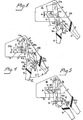
- a pliers device has a device body 10 which is rigidly connected to a structural unit 100 with a first operating handle 11.
- a second operating handle 12 which has a rigid extension 12a beyond its articulation point, is articulated to this assembly 100 by means of a pivot pin member 15a.
- a straight guideway 13 ′, 13 ′′ is arranged in the device body 10 for a jaw support 20 which is displaceably arranged therein and can be driven by the second operating handle 12 and which carries an exchangeable first working jaw member 22 by means of a retaining screw 21a.
- the direction E of the fixed handle 11 runs essentially parallel to the direction F of the guideway.
- a cooperating second work jaw member 22 is fixedly arranged in the device body 10 at the end of the guideway 13 ', 13 "by means of a retaining screw 22a. It is obvious that both work jaw members 21, 22 are also incorporated as non-exchangeable elements directly in the jaw support 20 or device body 10 can.
- a drive arm element in the above-mentioned sense, i.e. as the last link which acts directly on the jaw carrier, but such a drive member 14 is articulated in a fixed manner to the device body 10 by means of a pivot pin 14a, specifically at a point which is at a distance K from the guideway 13 ', 13 ".
- the distance K runs transversely to the direction F of the guideway 13 ', 13 "and on the opposite side thereof from where force is applied to the drive arm member 14, which is articulated by means of one to the drive arm member at 14b and to the extension 12a at 15b by means of a pivot pin member connected connecting strap member 15 happens.
- the drive arm member 14 also extends transversely to the direction F of the guideway, and the connecting line A of the two articulation points 14a, 14b occupied on the drive arm member forms an angle a with the direction F, which is between 45 ° and 135 ° in the open state of the device and in example shown is about 90 °.
- an open or closed state is understood to mean the state with working jaw organs that are distant or approximated to one another.
- the drive arm member 14 In its central area, approximately halfway between the two articulation points 14a, 14b, the drive arm member 14 carries a pin 14c which engages with the rear end wall 20a of the jaw support 20 and can slide along the wall 20a in the direction of the line A.
- a pressure or pull spring element can be in permanent engagement ensure these two parts, ie also outside the actual work process.
- Zan g s g evices this type including handles of two side parts, such as 100a, 100b (Fig. 6), eg connected by spacer organs metal plates, to produce, an average clearance 100 exists between which '.
- the devices according to the invention can also advantageously be produced in this way, and their drive arm and connecting plate members can then either consist of a single drive arm arranged in the above-mentioned central clearance or a single connecting plate, or each of a pair of these elements, such as drive arms 14 '. , 14; one of which is arranged along an outer surface of the device. 1 is provided with a pair of drive arms and a single connecting strap.
- the guideway can advantageously be formed by windows 13 arranged in both side parts with longitudinal edges 13 ', 13 ", the jaw support 20 having a middle part which extends somewhat more into the free space 100' and thus also being guided laterally by the side parts becomes.
- the drive arm member anchored in the device body 10 only transmits forces acting in the direction F of the guideway to the jaw carrier.
- the direction E of the first operating handle 11 extends obliquely to the direction F of the guideway, and forms an angle ⁇ of approximately 45 ° with it.
- the second operating handle 12 is articulated by means of the pivot pin 15a to a fixed projection 10a of the device body 10 and has an elongated slot 12c in its extension 12a, in which the pin 14b of the drive arm member 14 is slidably guided.
- the point of engagement of the pin 14b with the slot 12c shifts in this slot when the handle 12 is actuated, but remains here, like the device according to FIG. 1, at an unchanged distance from the pivot pin 14a, i.e. it moves along a circular path H with the center in the pivot pin 14a.
- the embodiment according to FIG. 3 is a kinematic revolution of the embodiment according to FIG. 2 in the sense that an elongated slot 14d in the drive arm member 14 and an engagement pin 12b is arranged on the extension 12a.
- the point of engagement of the pin 12a moves along the slot 14d when the handle 12 is actuated and moves along a circular path I with a fixed center, but this is now in the pin 15a.
- a kinematic difference between the embodiments according to FIGS. 2 and 3 and the other exemplary embodiments shown, which will be discussed in more detail later, is that When the handle 12 is actuated, the distance m 'between the pins 12a and 15a in the device according to FIG. 2, and the distance p between the pin 14a and the point of engagement in the slot 14d in the device according to FIG. 3, are approximately extended.
- a second operating handle 12 in the embodiment as shown in FIG. 3 is not articulated directly to the structural unit 100, but by means of a connecting bracket 15 ', similar to the connecting bracket 15 according to FIG.
- the first operating handle 11 extends obliquely to the device body 10 and preferably such that the direction F of the guideway 13 with the direction E of the first operating handle has an angle ⁇ of the order of 30 ° to 90 °, and with the axis of symmetry D of the most open operating handles 11, 12 includes an angle 'of 45 ° to 90 °.
- the line of symmetry D is understood to mean that line which bisects the angle ⁇ enclosed by the two operating handles 11, 12 in their mostly open position.
- the drive arm member 14 engages in the area between its two articulation points 14a, 14b with the jaw support 20 such that a mutual sliding movement in the longitudinal direction of the drive arm is possible between the two parts.
- this is achieved in that the pin 14c firmly anchored therein approximately half the length of the drive arm 14 'passes through an elongated hole 20b arranged in the jaw carrier 20.
- an identical second drive arm 14 "(Fig. 1,2) is arranged in which the opposite End of the pin 14c is anchored.
- a pin which is firmly anchored in the jaw support 20 and which slides in elongated holes in the drive arm member or the solution according to FIG. 1.
- the cooperating working jaw members 21, 22 are arranged in the jaw support 20 and in the device body 10, at the end of the guideway 13 ', 13 ", as in the past.
- it is a pair of jaws for pressing cable lugs onto electrical conductors, but it is obvious that any work jaw organs can be used.
- the device is expediently provided with a locking mechanism which is known per se and which prevents premature opening of the operating handles and the work jaw members.
- a locking mechanism is shown which comprises a circular row of teeth 15c and a locking hook 15c 'engaging with it.
- Such a locking mechanism for pliers is described in the Holdema A.G. British Patent 1,522,144 filed on October 25, 1974, which is hereby incorporated by reference.
- a locking mechanism acting between the two operating handles can be used, e.g. is described in the former British Patent 1,453,479.
- At least one of the pins 14a, 14b, 14c, 15a, 15b in all embodiments, can be designed eccentrically in accordance with FIG. 6, as is shown in FIG. 4 and 5 is shown for example in the pin 15a.
- the same also applies to the pins 12a, 12b in the embodiment according to FIG. 3.
- the peg in question that is to say 15a in the example shown, has two peripheral parts 15a ′, 15a ′′, which are concentric with a longitudinal axis C, and a central part 15a ′′ between them, which is eccentric to this axis C, and which the connecting tab 15 'is arranged.
- the pin 15a is mounted in the two side parts 100a and 100b of the structural unit 100 by means of the concentric parts 15a ', 15a ", so that its rotation about the axis C causes the mutual position of the two components connected by such a pin as part of the eccentricity
- the pin 15a is provided with a slotted head 150 and with a thread on which a tightenable nut is screwed in.
- the device according to the invention is advantageously designed in such a way that in the completely closed state according to FIG. 5, not in the open state as shown in FIG. 1, the drive arm 14 or the connecting line A of its two articulation points 14a, 14b essentially a right one Includes angle ⁇ ', or at least an angle in the range 80 ° to 100 °, with the guideway 13. The same also applies to the angle ⁇ with respect to the connecting line B of the two articulation points 14b, 15b, which are attached to the extension 12 '. With these angle values, the best power yield is achieved in the final phase of the jaw approach.
- the device works in the following way, as can best be seen in FIG Work object shown between the two work jaw members 21, 22 in the open state of the pair of jaws, the device is actuated by de second operating handle 12 in the direction of arrow P 1 is approximated to the first operating handle 11.
- the second operating handle 12 here performs a rotary movement around the pin 15b, its rigid extension 12a moving in the direction of the arrow P 2 in the opposite direction of the arrow p 1 .
- the drive arm element 14 is rotated in the direction of the arrow P 3 around its articulation point 14 a on the device body 10 and thereby gives the jaw support 20 a feed movement in the direction of the arrow P 5 , which, thanks to the guideway 13, is rectilinear.
- the two other pins 14c and 14b located on the drive arm element 144 describe circular movements along the paths G and H with centers in the pin 14a.
- the engagement of the drive arm element 14 with the jaw support 20 is designed in a sliding manner in the manner mentioned above, and on the other hand the second operating handle 12 is not articulated directly on the assembly 100, but rather on the connecting strap 15 ', which compensates for the vertical Component of said circular movement itself performs a circular movement in the direction of arrow P 4 and thus enables the second operating handle 12 to be “lifted” (see FIG. 4 with FIG. 5).
- FIGS. 4 and 5 shows a modification of the device according to FIGS. 4 and 5, which differs only in that the direction E of the first operating handle 11, in the same way as in the embodiment according to FIG. 1, is essentially parallel to the direction F of the guideway runs.
- the embodiments acc. 2 and 3 differ from all other embodiments shown, for example, in that the between the articulation or. Engagement points 15a and 14b acting lever arm with the variable length m 'in the embodiment according to FIG. 2, or E between the articulation point 14a and the engagement point in the slot 14d in the embodiment according to FIG. 3, when the operating handle 12 is actuated, something grows, which in turn is a somewhat less pronounced decrease in value As a result, the difference is insignificant.
- loads acting on this and / or the jaw support 20 transversely to the direction F of the guideway are absorbed by the fixedly articulated drive arm member, and forces acting only in the direction F mentioned are transferred to the jaw support.
- the design of the guideway in the form of a window 13 which is closed on all sides, and in particular both below and above the jaw support, further contributes to accurate guiding with minimal wear.
Landscapes
- Engineering & Computer Science (AREA)
- Mechanical Engineering (AREA)
- Manufacturing & Machinery (AREA)
- Gripping Jigs, Holding Jigs, And Positioning Jigs (AREA)
- Surgical Instruments (AREA)
- Manufacturing Of Electrical Connectors (AREA)
- Load-Engaging Elements For Cranes (AREA)
Abstract
Description
- Die Erfindung bezieht sich auf ein Zangengerät mit einem Gerätekörper und von der im Oberbegriff des angeschlossenen Anspruchs 1 angeführten Art, also ein Zangengerät bei welchem die eine Arbeitsbacke anstatt der bei Zangen meist üblichen scherenartigen Schwenkbewegung eine schraubstockartige geradlinige Bewegung gegenüber der anderen Arbeitsbacke durchführt. Ein bekanntes Gerät dieser Art ist z.B. in dem am 12.2 1973 von Pressmaster A.G. angemeldetem britischem Patent Nr. 1,453,479 in Fig. 2 dargestellt.
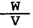
- Die geradlinige Führungsbahn der beweglichen Backe ist bei Geräten dieser Art ziemlich grossen Anstrengungen ausgesetzt, denn das Antriebsarmorgan (unter diesem Begriff wird in der vorliegenden Beschreibung das letzte, an die betreffende Backe direkt einwirkende Glied des Kniehebelmechanismus verstanden) wirkt auf die bewegliche Backe zumindest zeitweilig schräg zur Führungsbahn, und u.U. mit beträchtlicher Kraft, ein. Die Führungsbahn muss mit besonderer Hinsicht auf das Auffangen der senkrecht zur Führungsbahn wirkenden Komponente der Krafteinwirkung konstruiert werden, und dennoch können Abnützungseffekte nicht gänzlich ausgeschlossen werden welche die Genauigkeit der Führung beeinträchtigen,da sie zufolge von Verschleiss ein unerwünschtes Spiel in Richtung der genannten Komponente verursachen. Es ist ferner in den meisten Fällen bei Zangen wünschenswert:, dass eine Arbeitsbacke in der Schlussphase eines Bearbeitungsvorganges wie Verpressung od.dgl. mit grösserer Kraft an einen Arbeitsgegenstand einwirkt als am Anfang, wo der Arbeitsgegenstand kleineren Widerstand leistet. Unter Krafteinwirkung wird hierbei das Verhältnis


- Die Erfindung stellt sich die Aufgabe ein Zangengerät der angeführten Art zu schaffen bei dem die Beanspruchung der Führungsbahn quer zu deren Richtung abgeschafft oder zumindest erheblich vermindert-ist, und welches es ferner in einer Weiterentwicklung ermöglicht dass zusätzlich noch der Vorteil erreicht wird, dass der Wert h während des Arbeitsvorganges absinkt.
- Die Erfindungsaufgabe wird mittels der im kennzeichnenden Teil des genannten Anspruchs 1 angeführten Kennzeichen gelöst, wobei vorteilhafte Weiterentwicklungen in den angeschlossenen Unteransprüchen angeführt sind.
- Die Erfindung wird nun anhand der beigefügten schematischen Zeichnungen näher erläutert, wobei in den einzelnen Zeichnungsfiguren in Seitenansicht gezeigt wird:
- in Fig. 1 eine erste Ausführungsform des erfindungsgemässen Gerätes,
- " Fig. 2 eine zweite Ausführungsform,
- " Fig. 3 eine Abwandlung des Gerätes gemäss Fig. 2,
- " Fig. 4 eine dritte Ausführungsform,
- in Fig. 5 das Gerät gemäss Fig. 4 in geschlossener Lage,
- " Fig. 6 ein Detail des Gerätes gemäss Fig. 4 und 5 in grösserem Masstab und in Schnitt entlang der Ebene VI-VI in Fig. 4,
- " Fig. 7 ein kinematisches Schema der Arbeitsweise des Gerätes gemäss Fig. 4 und 5, und
- "Fig. 8 eine Abwandlung des Gerätes gemäss Fig. 4 och 5.
- Teile mit identischer oder analoger Funktion sind in allen Zeichnungsfiguren mit identischen oder analogen Bezugszeichen bezeichnet.
- Gemäss Fig. 1 weist ein erfindungsgemässes Zangengerät einen Gerätekörper 10 auf der mit einem ersten Bedienungshandgriff 11 starr zu einer Baueinheit 100 verbunden ist. An diese Baueinheit 100 ist mittels eines Schwenkzapfenorgans 15a ein zweiter Bedienungshandgriff 12 angelenkt der jenseites seiner Anlenkstelle eine starre Verlängerung 12a aufweist. Im Gerätekörper 10 ist eine geradlinige Führungsbahn 13',13" für einen darin'verschiebbar angeordneten und vom zweiten Bedienungshandgriff 12 antreibbaren Backenträger 20 angeordnet, der mittels einer Halteschraube 21a ein austauschbares erstes Arbeitsbackenorgan 22 trägt.
- Die Richtung E des festen Handgriffes 11 verläuft im wesentlichen parallel mit der Richtung F der Führungsbahn. Ein zusammenarbeitendes zweites Arbeitsbackenorgan 22 ist am Ende der Führungsbahn 13',13" mittels einer Halteschraube 22a fest im Gerätekörper 10 angeordnet. Es ist offensichtlich, dass beide Arbeitsbackenorgane 21, 22 auch als nicht austauschbare Elemente direkt im Backenträger 20 bzw. Gerätekörper 10 eingearbeitet sein können.
- So weit ist die Anordnung konventionell (mit Ausnahme der Gestaltung der Führungsbahn 13).
- Erfindungsgemäss ist an die Verlängerung 12a nicht ein Antriebsarmirgan in dem oben angeführten Sinne, d.h. als letztes, an den Backenträger direkt einwirkendes Glied angelenkt, sondern ein derartiges Antriebsorgan 14 ist mittels eines Schwenkzapfens 14a ortsfest an den Gerätekörper 10 angelenkt, und zwar in einer Stelle, welchen sich in einem Abstand K von der Führungsbahn 13',13" befindet. Der Abstand K verläuft quer zur Richtung F der Führungsbahn 13',13" und an entgegengesetzter Seite hiervon als wo Kraftbeaufschlagung des Antriebsarmorganes 14 stattfindet, was mittels eines an das Antriebsarmorgan bei 14b, und an die Verlängerung 12a bei 15b, mittels je eines Schwenkzapfenorganes gelenkig angeschlossen Verbindungslaschenorganes 15 geschieht.
- Das Antriebsarmorgan 14 verläuft ebenfalls quer zur Richtung F der Führungsbahn, und die Verbindungslinie A der beiden am Antriebsarmorgan belegenen Anlenkstellen 14a, 14b schliesst einen Winkel a mit der Richtung F ein, der in geöffnetem Zustand des Gerätes zwischen 45° und 135° liegt und im dargestellten Beispiel etwa 90° beträgt. Unter geöffnetem bzw. geschlossenem Zustand wird in der vorliegenden Beschreibung der Zustand mit von einander entfernten bzw. aneinander angenäherten Arbeitsbackenorganen verstanden.
- In seinem mittleren Bereich, etwa in halbem Abstand zwischen den beiden Anlenkstellen 14a, 14b, trägt das Antriebsarmorgan 14 einen Zapfen 14c der mit der hinteren Abschlusswand 20a des Backenträgers 20 in Eingriff steht und hierbei in Richtung der Linie A entlang der Wand 20a gleiten kann. Ein nicht dargestelltes Druck- oder Ziehfederorgan kann dauernden Eingriff dieser beiden Teile gewährleisten, d.h. auch ausserhalb des eigentlichen Arbeitsvorgangs.
- Es ist bekannt, Zangengeräte dieser Art inklusive Handgriffe aus zwei Seitenteilen wie 100a, 100b (Fig. 6), z.B. von Distanzorganen verbundenen Metallplatten, herzustellen, zwischen denen ein mittlerer Freiraum 100' besteht. Auch die erfindungsgemässen Geräte können mit Vorteil auf diese Weise hergestellt werden, und deren Antriebsarm- und Verbindungslaschenorgane können dann entweder aus einem einzigen, im genannten mittleren Freiraum angeordnetem Antriebsarm oder einer einzigen Verbindungslasche bestehen, oder jeweils aus einem Paar dieser Elemente, wie Antriebsarme 14', 14; von denen je eines entlang einer Aussenfläche des Gerätes angeordnet ist. Das Gerät gemäss Fig. 1 ist mit einem Paar Antriebsarme und einer einzigen Verbindungslasche versehen. Die Führungsbahn kann bei dieser Bauweise vorteilhafter Weise von in beiden Seitenteilen angeordneten Fenstern 13 mit Längskanten 13', 13" gebildet werden, wobei der Backenträger 20 einen etwas mehr in den Freiraum 100' hineinreichenden Mittelteil aufweist und somit von den Seitenteilen auch in seitlicher Richtung geführt wird.
- Das im Gerätekörper 10 verankerte Antriebsarmorgan überträgt nur in Richtung F der Führungsbahn wirkende Kräfte an den Backenträger . Der Umstand, dass die Führungsbahn in Form eines im Gerätekörper angeordneten Fensters 13 ausgeführt ist welches von allen Seiten geschlossen ist und nicht, wie üblich, bloss unter dem Bakkenträger 20 ein Führungsorgan 13' aufweist, sondern auch oberhalb des Backenträgers mit einem zweiten, parallelen Führungsorgan 13" versehen ist, trägt weiter dazu bei, dass frühzeitiger Verschleiss der zusammenarbeitenden Flächen der Führungsbahn und des Bakkenträgers vermieden wird. Ein derartiger Verschleiss hat zur Folge, dass die Endlage der Arbeitsbackenorgane nicht mehr eindeutig ist, und dies kann bei Arbeitsbacken mit anderer als geradliniger Form zu nichteinwandfreier Bearbeitung von Arbeitsstücken führen.
- In der Ausführungsform gemäss Fig. 2 verläuft die Richtung E des ersten Bedienungshandgriffs 11 schräg zur Richtung F der Führungsbahn, und schliesst mit dieser einen Winkel γ von etwa 45° ein. Der zweite Bedienungshandgriff 12 ist mittels des Schwenkzapfens 15a an einen festen Vorsprung 10a des Gerätekörpers 10 angelenkt und weist in seiner Verlägerung 12a einen länglichen Schlitz 12c auf, in dem der Zapfen 14b des Antriebsarmorganes 14 gleitend geführt wird. Die Eingriffsstelle des Zapfens 14b mit dem Schlitz 12c verlagert sich in diesem Schlitz bei der Betätigung des Handgriffes 12, bleibt aber hierbei, gleich wie beim Gerät gemäss Fig. 1, in unverändertem Abstand vom Schwenkzapfen 14a, d.h. sie bewegt sich entlang einer Kreisbahn H mit dem Mittelpunkt im Schwenkzapfen 14a.
- Die Ausführungsform gemäss Fig. 3 ist eine kinematische Umdrehung der Ausführungsform gemäss Fig. 2 in dem Sinne, dass ein länglicher Schlitz 14d im Antriebsarmorgan 14 , und ein Eingriffszapfen 12b an der Verlängerung 12a angeordnet ist. Die Eingriffsstelle des Zapfens 12a wandert auch in diesem Fall bei Betätigung des Handgriffes 12 entlang des Schlitzes 14d und bewegt sich entlang einer Kreisbahn I mit festem Mittelpunkt, dieser liegt nun aber im Zapfen 15a. Ein kinematischer Unterschied zwischen den Ausführungsformen gemäss Fig. 2 und 3 und den übrigen dargestellten beispielsweisenAusführungsformen, auf den später noch näher eingegangen werden wird, besteht darin, dass sich bei Betätigung des Handgriffes 12 der Abstandm' zwischen den Zapfen 12a und 15a beim Gerät gemäss Fig. 2, sowie der Abstand p zwischen dem Zapfen 14a und der Eingriffsstelle im Schlitz 14d beim Gerät gemäss Fig. 3, etwa verlängert.
- In der dritten Ausführungsform gemäss Fig. 4 und 5 ist ein zweiter Bedienungshandgriff 12 in Ausführungsform wie gemäss Fig. 3 an die Baueinheit 100 nicht direkt, sondern mittels eines Verbindungslaschenorgans 15', ähnlich dem Verbindungslaschenorgan 15 gemäss Fig. l, angelenkt.
- Der erste Bedienungshandgriff 11 verläuft schräg zum Gerätekörper 10 und vorzugsweise so, dass die Richtung F der Führungsbahn 13 mit der Richtung E des ersten Bedienungshandgriffes einen Winkel γ in der Grössenordnung von 30° bis 90°, und mit der Symmetrieachse D der am weitesten geöffneten Bedienungshandgriffe 11, 12 einen Winkel 'von 45° bis 90° einschliesst. Mit genannter Symmetriachse D wird diejenige Linie verstandenwelche den von den beiden Bedienungshandgriffen 11, 12 in deren meist geöffneter Lage eingeschlossenen Winkel δ halbiert.
- Das Antriebsarmorgan 14 greift im Bereich zwischen seinen beiden Anlenkstellen 14a, 14b derart mit dem Backenträger 20 ein, dass zwischen den beiden Teilen eine gegenseitige Gleitbewegung in Längsrichtung des Antriebsarmes möglich ist. Im dargestellten Beispiel wird dies dadurch erreicht, dass der etwa in halber Länge des Antriebarmes 14' darin fest verankerter Zapfen 14c durch ein im Backenträger 20 angeordnetes Langloch 20b hindurchgeht. An der abgekehrten Seite des Gerätekörpers 10 ist ein identischer zweiter Antriebsarm 14" (Fig. 1,2) angeordet in dem das abgekehrte Ende des Zapfens 14c verankert ist. Es ist jedoch offensichtlich, dass auch andere Lösungen des gleitenden Eingriffes dieser beiden Teile möglich sind, z.B. ein im Backenträger 20 fest verankerter Zapfen der in Langlöchern in den Antriebsarmorgan gleitet, oder die Lösung gemäss Fig. 1.
- Im Backenträger 20 und im Gerätekörper 10, am Ende der Führungsbahn 13',13", sind wie früher die zusammenarbeitenden Arbeitsbackenorgane 21, 22 angeordnet. Im dargestellten Beispiel handelt es sich um ein Bakkenpaar zum Festpressen von Kabelschuhen an elektrische Leiter, aber es ist offensichtlich, dass beliebige Arbeitsbackenorgane angewandt werden können.
- Zweckmässiger Weise wird das Gerät mit einem an sich bekannten Sperrmechanismus versehen der ein vorzeitiges öffnen der Bedienungshandgriffe und der Arbeitsbackenorgane verhindert. Im dargestellten Beispiel wird ein Sperrmechanismus gezeigt, der eine kreisbogenförmige Zahnreihe 15c und einen mit ihr eingreifenden Sperrhaken 15c' umfasst. Ein derartiger Sperrmechanismus für Zangen ist in dem von Holdema A.G. am 25. Oktober 1974 angemeldeten britischen Patent 1,522,144 näher beschrieben, auf welches hiermit hingewiesen wird. Alternativ kann ein zwichen den beiden Bedienungshandgriffen wirkender Sperrmechanismus angewandt werden, wie er z.B. in der erstgenannten britischen Patentsschrift 1,453,479 beschrieben ist.
- Ferner kann zur genauen Einstellung der in Fig. 5 gezeigten geschlossenen Endlage des Gerätes zumindest einer der Zapfen 14a, 14b, l4c, l5a, 15b, in allen Ausführungsformen in an sich bekannter Weise gemäss Fig. 6 exzentrisch ausgeführt werden, wie dies in Fig. 4 und 5 beispielsweise bei dem Zapfen 15a gezeigt ist. Das Gleiche trifft auch für die Zapfen 12a, 12b, in der Ausführungsform gemäss Fig. 3 zu.
- Der betreffende Zapfen, also 15a im dargestellten Beispiel, weist zwei periphere Teile 15a', 15a", die konzentrich zu einer Längsachse C sind, und einen zwischen ihnen belegenen mittleren Teil 15a"' auf, welcher zu dieser Achse C exzentrisch ist, und auf welchem die Verbindungslasche 15' angeordnet ist. Mittels der konzentrischen Teile 15a', 15a" ist der Zapfen 15a in den beiden Seitenteilen 100a und 100b der Baueinheit 100 gelagert, so dass durch seine Drehung um die Achse C herum die gegenseitige Lage der beiden von so einem Zapfen verbundenen Bauteile im Rahmen der Exzentrizität geändert werden kann. Zur Durchführung und Sicherung einer derartigenEinstellung ist der Zapfen 15a mit einem geschlitzten Kopf 150 und mit einem Gewinde, auf dem eine anziehbare Mutter aufgeschraubt ist, versehen. Für nähere Einzelheiten betreffend eine derartige Einstellanordnung wird auf die angeführte britische Patentschrift 1,522,144 hingewiesen.
- Vorteilhafter Weise wird das erfindungsgemässe Gerät derart gestaltet, dass in völlig geschlossenem Zustand gemäss Fig. 5,nicht also in geöffnetem Zustand, wie in Fig. 1 dargestellt, der Antriebsarm 14 bzw. die Verbindungslinie A seiner beiden Anlenkstellen 14a, 14b im wesentlichen einen rechten Winkel α', oder zumindest einen Winkel der im Bereich 80° bis 100° liegt, mit der Führungsbahn 13 einschliesst. Das Gleiche gilt auch für den Winkel β gegenüber der Verbindunqslinie B der beiden an der Verlänqerunq 12' beleqenen Anlenkstellen 14b, 15b. Bei diesen Winkelwerten wird die beste Kraftausbeute in der Schlussphase der Backenannäherunq erreicht.
- Das Gerät arbeitet auf folgende Weise, wie am besten aus Fig. 7 hervorgeht: Nach Einlegen eines nicht dargestellten Arbeitsgegenstandes zwischen die beiden Arbeitsbackenorgane 21, 22 in geöffnetem Zustand des Backenpaares wird das Gerät betätigt indem de zweite Bedienungshandgriff 12 im Sinne des Pfeiles P1 an den ersten Bedienungshandgriff 11 angenähert wird. Der zweite Bedienungshandgriff 12 führt hierbei eine Drehbewegung um den Zapfen 15b herum aus, wobei sich seine starre Verlängerung 12a im Sinne des Pfeiles P2 entgegen dem Sinn des Pfeiles p1 bewegt. Hierdurch wird das Antriebsarmorgan l4 im Sinne des Pfeiles P3 um seine Anlenkstelle 14a an den Gerätekörper 10 herum verdreht und erteilt dadurch dem Backenträger 20 eine Vorschubbewegung im Sinne des Pfeiles P5, die dank der Führungsbahn 13 geradlinig ist. Infolge der Drehbewegung um den Zapfen 14a herum beschreiben die zwei anderen am Antriebsarmorgan l4 befintlichen Zapfen 14c und 14b Kreisbewegungen entlang der Bahnen G und H mit Mittelpunkten im Zapfen 14a. Um dies zu ermöglichen, ist einerseites der Eingriff des Antriebsarmorgans l4 mit dem Backenträger 20 in oben angeführter Weise gleitend gestaltet, und anderseits ist der zweite Bedienungshandgriff 12 nicht direkt an der Baueinheit 100, sondern an der Verbindungslasche 15' angelenkt, welche zur Kompensation der vertikalen Komponente der genannten Kreisbewegung selber eine Kreisbewegung im Sinne des Pfeiles P4 durchführt und somit ein "Anheben" (vergleiche Fig. 4 mit Fig. 5) des zweiten Bedienungshandgriffes 12 ermöglicht.
- Es hat sich herausgestellt, dass folgende Längenverhältnisse vorteilhaft sind:
- a) Der Antriebsarm 14 greift innerhalb des mittleren Drittels des Abstandes t zwischen 14a und 14b mit dem Backenträger 20 ein, vorzugsweise in der Mitte (ℓ/2).
- b) Die Abstände m zwischen 14b und 15b einerseits, und n zwischen 15a und 15b anderseits sind im wesentlichen einander gleich und unterscheiden sich höchsten um + 25%.
- c) Der oben genannte Abstand ℓ bildet ein Dreibis Vierfaches der Abstände m oder n.
- In Fig. 8 ist eine Abwandlung des Gerätes gemäss Fig. 4 und 5 dargestellt die sich nur dadurch unterscheidet, dass die Richtung E des ersten Bedienungshandgriffes 11,gleich wie bei der Ausführungsform gemäss Fig. l,im wesentlichen parallel mit der Richtung F der Führungsbahn verläuft.
- Die Ausführungsformen gem. Fig. 2 und 3 unterscheiden sich von allen übrigen beispielsweise dargestellten Ausführungsformen dadurch, dass der zwischen den Anlenk-bzw. Eingriffsstellen 15a und 14b wirkende Hebelarm mit der veränderlichen Länge m' bei der Ausführungsform gemäss 2, bzw. E zwischen der Anlenkstelle 14a und der Eingriffstelle im Schlitz 14d bei der Ausführungsform gemäss Fig. 3,bei Betätigung des Bedienungshandgriffes 12 etwas anwächst, was seinerseits eine etwas weniger ausgeprägte Verminderung des Wertes

- In allen Ausführungsformen des erfindungsgemässen Gerätes werden quer zur Richtung F der Führungsbahn auf diese und/oder den Backenträger 20 einwirkende Belastungen vom ortsfest angelenkten Antriebsarmorgan aufgefangen, und nur in genannter Richtung F wirkende Kräfte an den Backenträger überführt. Die Gestaltung der Führungsbahn in Form eines allseitig, und insbesondere sowohl unterhalb, als auch oberhalb des Backenträgers geschlossenen Fensters 13 trägt weiter zur genauen Führung mit minimalem Verschleiss bei.
Claims (10)
Applications Claiming Priority (2)
| Application Number | Priority Date | Filing Date | Title |
|---|---|---|---|
| SE8204888 | 1982-08-26 | ||
| SE8204888A SE429621B (sv) | 1982-08-26 | 1982-08-26 | Tangverktyg med retlinjigt rorlig arbetskeft |
Publications (2)
| Publication Number | Publication Date |
|---|---|
| EP0103912A1 true EP0103912A1 (de) | 1984-03-28 |
| EP0103912B1 EP0103912B1 (de) | 1986-02-26 |
Family
ID=20347630
Family Applications (1)
| Application Number | Title | Priority Date | Filing Date |
|---|---|---|---|
| EP83200979A Expired EP0103912B1 (de) | 1982-08-26 | 1983-07-01 | Zangengerät |
Country Status (5)
| Country | Link |
|---|---|
| US (1) | US4526070A (de) |
| EP (1) | EP0103912B1 (de) |
| JP (1) | JPS5954182A (de) |
| DE (1) | DE3362289D1 (de) |
| SE (1) | SE429621B (de) |
Cited By (6)
| Publication number | Priority date | Publication date | Assignee | Title |
|---|---|---|---|---|
| EP0203241A1 (de) * | 1985-05-21 | 1986-12-03 | Etablissements Pierre Grehal Et Compagnie | Mehrzweckzange und ihre Verwendung zum Befestigen, Pressen, Lochen und dergleichen |
| FR2597384A1 (fr) * | 1986-04-22 | 1987-10-23 | Deloubes Jean Pierre | Disposition de montage et d'articulation multipliant la poussee pour coupe boulons, coupe cables, secateur a 2 mains et pneumatique, pince coupante a main. |
| EP0202790B1 (de) * | 1985-05-17 | 1989-12-13 | Mike & Kremmel Limited | Büchsenöffner |
| FR2741830A1 (fr) * | 1995-12-05 | 1997-06-06 | Pierre Grehal Et Compagnie Sa | Pince d'usinage a fonctions multiples |
| EP0865880A1 (de) * | 1996-12-09 | 1998-09-23 | Etablissements Pierre Grehal Et Compagnie Sa | Mehrzweckzange |
| DE19807737A1 (de) * | 1998-02-24 | 1999-09-02 | Wezag Gmbh | Zange zum Verpressen von Werkstücken |
Families Citing this family (12)
| Publication number | Priority date | Publication date | Assignee | Title |
|---|---|---|---|---|
| US4811441A (en) * | 1988-06-10 | 1989-03-14 | Stride Tool Inc., A New York Corporation | Tool for trimming hose and inserting fitting |
| DE4129685A1 (de) * | 1991-09-07 | 1993-03-11 | Wolfgang B Thoerner | Handbetaetigte crimp-zange |
| US5704106A (en) * | 1991-12-30 | 1998-01-06 | Value Plastics, Inc. | Modular tubing assembly device |
| AU662056B2 (en) * | 1992-04-06 | 1995-08-17 | Pressmaster Tool Ab | A crimping tool |
| US5870925A (en) * | 1997-06-27 | 1999-02-16 | The Whitaker Corporation | Hand tool crimping a terminal onto a conductor |
| US7086312B1 (en) | 2001-12-28 | 2006-08-08 | Kenneth Guy Tortolani | Parallel jaw locking toggle wrench/pliers with economic/ergonomic handles |
| USD455325S1 (en) | 2001-09-13 | 2002-04-09 | Rostra Tool Company | Compression tool |
| US6629443B2 (en) * | 2002-01-16 | 2003-10-07 | Yen Chao Chin | Ergonomic crimping apparatus |
| DE102008012011B3 (de) * | 2008-03-01 | 2009-12-03 | Wezag Gmbh Werkzeugfabrik | Zangenkopf |
| CN103128533B (zh) * | 2013-03-21 | 2015-11-18 | 河北亚大汽车塑料制品有限公司 | 一种塑料管路总成手动装配机 |
| US11212965B1 (en) * | 2021-01-28 | 2022-01-04 | Lester Duane Hames | Tool for deep selective pruning of branches and vines |
| CN116291207A (zh) * | 2023-04-19 | 2023-06-23 | 中海油田服务股份有限公司 | 旋转导向推靠臂及旋转导向钻井系统 |
Citations (5)
| Publication number | Priority date | Publication date | Assignee | Title |
|---|---|---|---|---|
| DE273847C (de) * | ||||
| US2320303A (en) * | 1941-04-28 | 1943-05-25 | Clifford O Ross | Mechanic's tool |
| GB1453479A (en) * | 1973-02-12 | 1976-10-20 | Pressmaster Ltd | Crimping tool |
| US4031735A (en) * | 1975-02-27 | 1977-06-28 | The Post Office | Apparatus for joining wires |
| GB1522144A (en) * | 1975-10-24 | 1978-08-23 | Holdema Ltd | Crimping and/or cutting device |
Family Cites Families (2)
| Publication number | Priority date | Publication date | Assignee | Title |
|---|---|---|---|---|
| US432056A (en) * | 1890-07-15 | Dehorning device | ||
| US3238763A (en) * | 1963-09-05 | 1966-03-08 | Frost Eng Dev | Plier-type hand tool |
-
1982
- 1982-08-26 SE SE8204888A patent/SE429621B/sv not_active IP Right Cessation
-
1983
- 1983-07-01 EP EP83200979A patent/EP0103912B1/de not_active Expired
- 1983-07-01 DE DE8383200979T patent/DE3362289D1/de not_active Expired
- 1983-08-16 JP JP58148866A patent/JPS5954182A/ja active Granted
- 1983-08-25 US US06/526,438 patent/US4526070A/en not_active Expired - Fee Related
Patent Citations (5)
| Publication number | Priority date | Publication date | Assignee | Title |
|---|---|---|---|---|
| DE273847C (de) * | ||||
| US2320303A (en) * | 1941-04-28 | 1943-05-25 | Clifford O Ross | Mechanic's tool |
| GB1453479A (en) * | 1973-02-12 | 1976-10-20 | Pressmaster Ltd | Crimping tool |
| US4031735A (en) * | 1975-02-27 | 1977-06-28 | The Post Office | Apparatus for joining wires |
| GB1522144A (en) * | 1975-10-24 | 1978-08-23 | Holdema Ltd | Crimping and/or cutting device |
Cited By (8)
| Publication number | Priority date | Publication date | Assignee | Title |
|---|---|---|---|---|
| EP0202790B1 (de) * | 1985-05-17 | 1989-12-13 | Mike & Kremmel Limited | Büchsenöffner |
| EP0203241A1 (de) * | 1985-05-21 | 1986-12-03 | Etablissements Pierre Grehal Et Compagnie | Mehrzweckzange und ihre Verwendung zum Befestigen, Pressen, Lochen und dergleichen |
| FR2597384A1 (fr) * | 1986-04-22 | 1987-10-23 | Deloubes Jean Pierre | Disposition de montage et d'articulation multipliant la poussee pour coupe boulons, coupe cables, secateur a 2 mains et pneumatique, pince coupante a main. |
| FR2741830A1 (fr) * | 1995-12-05 | 1997-06-06 | Pierre Grehal Et Compagnie Sa | Pince d'usinage a fonctions multiples |
| EP0865880A1 (de) * | 1996-12-09 | 1998-09-23 | Etablissements Pierre Grehal Et Compagnie Sa | Mehrzweckzange |
| DE19807737A1 (de) * | 1998-02-24 | 1999-09-02 | Wezag Gmbh | Zange zum Verpressen von Werkstücken |
| US6026671A (en) * | 1998-02-24 | 2000-02-22 | Wezag Gmbh Werkzeugfabrik | Pliers for crimping workpieces |
| DE19807737C2 (de) * | 1998-02-24 | 2000-06-21 | Wezag Gmbh | Zange zum Verpressen von Werkstücken |
Also Published As
| Publication number | Publication date |
|---|---|
| JPS6352433B2 (de) | 1988-10-19 |
| EP0103912B1 (de) | 1986-02-26 |
| SE429621B (sv) | 1983-09-19 |
| US4526070A (en) | 1985-07-02 |
| DE3362289D1 (en) | 1986-04-03 |
| SE8204888D0 (sv) | 1982-08-26 |
| JPS5954182A (ja) | 1984-03-28 |
Similar Documents
| Publication | Publication Date | Title |
|---|---|---|
| EP0103912B1 (de) | Zangengerät | |
| EP0022122B1 (de) | Biegemaschine | |
| EP0516598B1 (de) | Zange mit wahlweiser frontaler und seitlicher Einführung | |
| DE8814208U1 (de) | Klammer zum Verbinden von Schaltafeln | |
| DE3434009A1 (de) | Werkstueck-handhabungsgeraet | |
| DE102020105722A1 (de) | Nullpunktspannplatte, und Werkzeugmaschine mit selbiger | |
| DE2755482C2 (de) | ||
| DE10206773C1 (de) | Vorrichtung zum Vorschieben von Werkstücken mit Greiferschienen | |
| DE69303129T2 (de) | Feststellvorrichtung | |
| EP0295725B1 (de) | Zangengerät | |
| DE2555071C2 (de) | Handbetätigtes Gerät zum Verpressen von Kabelschuhen, Kabelverbindern o.dgl. | |
| DE2206116C3 (de) | Zugvorrichtung mit zwei gleichzeitig hin- und herbewegbaren Gesperren | |
| EP1527847A2 (de) | Klemmen-Handwerkzeug | |
| DE69700231T2 (de) | Selbstzentrierende Lünette mit einfahrbaren Greifarmen | |
| DE69010044T2 (de) | Riegelmechanismus für Schiebetüren und Fenster. | |
| DE1447355B2 (de) | Vorrichtung zur schrittweisen Verstellung eines Schlittens | |
| DE2913816C2 (de) | ||
| DE1628041C3 (de) | Werkzeug zum Aufeinanderzuführen eines Matrizenpaares | |
| DE102010007917B4 (de) | Handbetätigtes Werkzeug | |
| DE2404161A1 (de) | Werkzeug, vorzugsweise zange, zum kerben bzw. verpressen von huelsen wie kabelschuhen u.dgl | |
| EP0305767A2 (de) | Klemmvorrichtung für einen Schlitten einer Werkzeugmaschine | |
| DE2635723C2 (de) | Verstellbarer Spaltmechanismus | |
| DE1477405B2 (de) | Einstellvorrichtung fuer werkzeugtraeger, insbesondere fuer bohrstangen von feinbohrmaschinen mit einer drehbaren bohrspindel | |
| DE69019963T2 (de) | Werkzeugführungseinrichtung. | |
| EP0635199A1 (de) | Gerät mit zwei Schenkeln und zwei Handgriffen |
Legal Events
| Date | Code | Title | Description |
|---|---|---|---|
| PUAI | Public reference made under article 153(3) epc to a published international application that has entered the european phase |
Free format text: ORIGINAL CODE: 0009012 |
|
| AK | Designated contracting states |
Designated state(s): CH DE FR GB IT LI |
|
| 17P | Request for examination filed |
Effective date: 19840210 |
|
| ITF | It: translation for a ep patent filed | ||
| GRAA | (expected) grant |
Free format text: ORIGINAL CODE: 0009210 |
|
| AK | Designated contracting states |
Designated state(s): CH DE FR GB IT LI |
|
| REF | Corresponds to: |
Ref document number: 3362289 Country of ref document: DE Date of ref document: 19860403 |
|
| ET | Fr: translation filed | ||
| PLBE | No opposition filed within time limit |
Free format text: ORIGINAL CODE: 0009261 |
|
| STAA | Information on the status of an ep patent application or granted ep patent |
Free format text: STATUS: NO OPPOSITION FILED WITHIN TIME LIMIT |
|
| 26N | No opposition filed | ||
| ITTA | It: last paid annual fee | ||
| PGFP | Annual fee paid to national office [announced via postgrant information from national office to epo] |
Ref country code: FR Payment date: 19910111 Year of fee payment: 9 |
|
| PGFP | Annual fee paid to national office [announced via postgrant information from national office to epo] |
Ref country code: CH Payment date: 19910514 Year of fee payment: 9 |
|
| PGFP | Annual fee paid to national office [announced via postgrant information from national office to epo] |
Ref country code: DE Payment date: 19910702 Year of fee payment: 9 |
|
| PGFP | Annual fee paid to national office [announced via postgrant information from national office to epo] |
Ref country code: GB Payment date: 19920619 Year of fee payment: 10 |
|
| PG25 | Lapsed in a contracting state [announced via postgrant information from national office to epo] |
Ref country code: LI Effective date: 19920731 Ref country code: CH Effective date: 19920731 |
|
| PG25 | Lapsed in a contracting state [announced via postgrant information from national office to epo] |
Ref country code: FR Effective date: 19930331 |
|
| REG | Reference to a national code |
Ref country code: CH Ref legal event code: PL |
|
| PG25 | Lapsed in a contracting state [announced via postgrant information from national office to epo] |
Ref country code: DE Effective date: 19930401 |
|
| REG | Reference to a national code |
Ref country code: FR Ref legal event code: ST |
|
| PG25 | Lapsed in a contracting state [announced via postgrant information from national office to epo] |
Ref country code: GB Effective date: 19930701 |
|
| GBPC | Gb: european patent ceased through non-payment of renewal fee |
Effective date: 19930701 |