EP0103956A2 - Automatischer Werkzeugwechsler mit kurvenförmiger Werkzeugbewegung - Google Patents
Automatischer Werkzeugwechsler mit kurvenförmiger Werkzeugbewegung Download PDFInfo
- Publication number
- EP0103956A2 EP0103956A2 EP83304291A EP83304291A EP0103956A2 EP 0103956 A2 EP0103956 A2 EP 0103956A2 EP 83304291 A EP83304291 A EP 83304291A EP 83304291 A EP83304291 A EP 83304291A EP 0103956 A2 EP0103956 A2 EP 0103956A2
- Authority
- EP
- European Patent Office
- Prior art keywords
- tool
- bucket
- transfer
- transfer point
- tool holder
- Prior art date
- Legal status (The legal status is an assumption and is not a legal conclusion. Google has not performed a legal analysis and makes no representation as to the accuracy of the status listed.)
- Withdrawn
Links
Images




Classifications
-
- B—PERFORMING OPERATIONS; TRANSPORTING
- B23—MACHINE TOOLS; METAL-WORKING NOT OTHERWISE PROVIDED FOR
- B23Q—DETAILS, COMPONENTS, OR ACCESSORIES FOR MACHINE TOOLS, e.g. ARRANGEMENTS FOR COPYING OR CONTROLLING; MACHINE TOOLS IN GENERAL CHARACTERISED BY THE CONSTRUCTION OF PARTICULAR DETAILS OR COMPONENTS; COMBINATIONS OR ASSOCIATIONS OF METAL-WORKING MACHINES, NOT DIRECTED TO A PARTICULAR RESULT
- B23Q3/00—Devices holding, supporting, or positioning work or tools, of a kind normally removable from the machine
- B23Q3/155—Arrangements for automatic insertion or removal of tools, e.g. combined with manual handling
- B23Q3/1552—Arrangements for automatic insertion or removal of tools, e.g. combined with manual handling parts of devices for automatically inserting or removing tools
- B23Q3/15526—Storage devices; Drive mechanisms therefor
- B23Q3/15534—Magazines mounted on the spindle
-
- B—PERFORMING OPERATIONS; TRANSPORTING
- B23—MACHINE TOOLS; METAL-WORKING NOT OTHERWISE PROVIDED FOR
- B23Q—DETAILS, COMPONENTS, OR ACCESSORIES FOR MACHINE TOOLS, e.g. ARRANGEMENTS FOR COPYING OR CONTROLLING; MACHINE TOOLS IN GENERAL CHARACTERISED BY THE CONSTRUCTION OF PARTICULAR DETAILS OR COMPONENTS; COMBINATIONS OR ASSOCIATIONS OF METAL-WORKING MACHINES, NOT DIRECTED TO A PARTICULAR RESULT
- B23Q3/00—Devices holding, supporting, or positioning work or tools, of a kind normally removable from the machine
- B23Q3/155—Arrangements for automatic insertion or removal of tools, e.g. combined with manual handling
- B23Q3/157—Arrangements for automatic insertion or removal of tools, e.g. combined with manual handling of rotary tools
- B23Q3/15713—Arrangements for automatic insertion or removal of tools, e.g. combined with manual handling of rotary tools a transfer device taking a single tool from a storage device and inserting it in a spindle
-
- B—PERFORMING OPERATIONS; TRANSPORTING
- B23—MACHINE TOOLS; METAL-WORKING NOT OTHERWISE PROVIDED FOR
- B23Q—DETAILS, COMPONENTS, OR ACCESSORIES FOR MACHINE TOOLS, e.g. ARRANGEMENTS FOR COPYING OR CONTROLLING; MACHINE TOOLS IN GENERAL CHARACTERISED BY THE CONSTRUCTION OF PARTICULAR DETAILS OR COMPONENTS; COMBINATIONS OR ASSOCIATIONS OF METAL-WORKING MACHINES, NOT DIRECTED TO A PARTICULAR RESULT
- B23Q3/00—Devices holding, supporting, or positioning work or tools, of a kind normally removable from the machine
- B23Q3/155—Arrangements for automatic insertion or removal of tools, e.g. combined with manual handling
- B23Q3/157—Arrangements for automatic insertion or removal of tools, e.g. combined with manual handling of rotary tools
- B23Q3/15713—Arrangements for automatic insertion or removal of tools, e.g. combined with manual handling of rotary tools a transfer device taking a single tool from a storage device and inserting it in a spindle
- B23Q3/1572—Arrangements for automatic insertion or removal of tools, e.g. combined with manual handling of rotary tools a transfer device taking a single tool from a storage device and inserting it in a spindle the storage device comprising rotating or circulating storing means
- B23Q3/15724—Chains or belts
-
- B—PERFORMING OPERATIONS; TRANSPORTING
- B23—MACHINE TOOLS; METAL-WORKING NOT OTHERWISE PROVIDED FOR
- B23Q—DETAILS, COMPONENTS, OR ACCESSORIES FOR MACHINE TOOLS, e.g. ARRANGEMENTS FOR COPYING OR CONTROLLING; MACHINE TOOLS IN GENERAL CHARACTERISED BY THE CONSTRUCTION OF PARTICULAR DETAILS OR COMPONENTS; COMBINATIONS OR ASSOCIATIONS OF METAL-WORKING MACHINES, NOT DIRECTED TO A PARTICULAR RESULT
- B23Q3/00—Devices holding, supporting, or positioning work or tools, of a kind normally removable from the machine
- B23Q3/155—Arrangements for automatic insertion or removal of tools, e.g. combined with manual handling
- B23Q3/1552—Arrangements for automatic insertion or removal of tools, e.g. combined with manual handling parts of devices for automatically inserting or removing tools
- B23Q3/15526—Storage devices; Drive mechanisms therefor
- B23Q2003/15532—Storage devices; Drive mechanisms therefor the storage device including tool pots, adaptors or the like
Definitions
- This invention relates generally to automatic tool changers for machine tools, and more particularly to a tool changer particularly well suited to machining centers having limited tool spindle travel.
- Automatic tool changers for machine tools have been known for many years. Generally speaking, they provide the advantages of greater speed and less operator effort in the performance of various machining operations on a workpiece. Their advantages have been sufficient to justify serious consideration of them for machine tools which are much smaller and less expensive than those on which automatic tool changers have been employed in most instances heretofore. Size, weight, available installation space, required space for operating the tool changer, complexity, cost, and reliability, have continued to be problems attendant the efforts to provide automatic tool changers for relatively small and inexpensive milling machines.
- the present invention is directed toward improving the speed and dependability, and reducing cost of an automatic tool changer requiring minimal vertical space between the spindle and the workpiece at the time of tool change.
- a tool changer assembly mountable to the side of a vertical milling machine head includes tool storage buckets on an endless belt conveyor in a storage housing, with reversible conveyor drive.
- the tool storage buckets have side openings for miminum swing-up of the tool during tool removal.
- Wide-opening tool transfer fingers provide direct tool transfer between machine spindle and storage bucket through an opening in the bottom of the housing.
- a power-operated sliding door normally closes the opeing.
- a milling machine is shown fragmentarily at 11 and includes a combination frame and cabinet 12 with a head 14 mounted to it, horizontally movable to the front and rear in the "Y" axis direction
- a saddle 16 is mounted to the frame and is movable up and down on ways 15 in the "Z" axis direction.
- a work table 17 is mounted to the saddle and is movable to the left and right, this being the "X" axis direction.
- a spindle assembly 18 projects up into the head 14, and includes a collet therein to receive a tool holder (dotted line) 19 and holds a tool therein, such as a drill 21 (dotted line), for example. All of these features can be found in a model KMB-I three-axis CNC Machining System manufactured by Hurco Manufacturing Company, Inc., of Indianapolis, Indiana.
- An automatic tool changer is provided on the milling machine and includes a housing 22 and conveyor support plate 23 which serves as the automatic tool changer housing bottom. This is affixed to the machine head 14
- Fig. 1A is primarily intended for a conceptual illustration of the invention, many details are omitted.
- the plate 23 supports an endless chain conveyor which has a plurality of tool storage buckets 24 spaced along and secured to the endless chain 26. Two such buckets are shown in Fig. lA, bucket 24A being in a position for unloading a tool from it or loading a tool into it, this being referred to as a load/unload position or tool transfer point.
- Bucket 24B is behind 24A on the chain.
- a tool holder 27 rests in the bucket 24A, and tool holder 28 rests in the bucket 24B.
- Each of these tool holders has a tool such as drill 29 in holder 27 and drill 31 in holder 28.
- These tool holders are of a conventional type well known and widely used in the art.
- Each has a circumferential groove 32 therein particularly suited to receiving the gripping fingers of a tool transfer mechanism in an automatic tool changer.
- the gripping fingers are shown at 33 and 34 (Fig. 1B). They are pivotally mounted to a gear block 36 which is mounted to pivot on a horizontal axis centered at 37.
- the finger axis for finger 33 is shown at 33C in Fig. lA. It is at an angle of 10° from vertical. Accordingly, the finger 33 is upwardly inclined at 10° from horizontal. The purpose of this will become apparent as the description proceeds.
- Figs. 1A through 6A and 1B through 6B if it is desired to transfer a tool from the storage magazine, with the machine at rest as shown in Figs. 1A and 1B, the conveyor is driven around to place the bucket for the desired tool in the load/unload station where bucket 24A is located in Fig. 1.
- the gear block 36 is then pivoted about horizontal axis 37 in the direction of arrow 38 (Fig. 2A) to place the finger 33 in the position shown in Fig. ' 2A, immediately above and almost flush with the top of bucket 24A and hold it there.
- the fingers are closed as shown in Fig. 2B, whereupon the semicircular claws thereof are received in the circumferential groove 32 in the tool holder.
- the gear block 36 is rocked back to the original position as shown in Figs. 1A and 3A, whereupon it removes the tool holder 27 from the bucket 24A. It is then in the position shown in Fig. 3A. Then the conveyor can be moved either backward or forward sufficiently that the fingers can swing downward in the direction of arrow 39 in Fig. 4A with the tool holder and tool therein without interferring with any of the conveyor buckets. If the conveyor is moved backward (clockwise as viewed in Fig. 7) to accomplish this, bucket 24A would then be in a "clear tool" position shown by dotted line 24AA in Fig. 7.
- the tool holder is specifically rotationally indexed with respect to the spindle in the present case by means of a key on the spindle received in a notch in the tool holder, much like the key 155 in the spindle of the above-mentioned Roch patent is received in the notch in the tool holder clamped in the spindle.
- the fingers After the tool holder has been securely clamped in the spindle, the fingers again open to an essentially 90° angle between them as shown in Fig. 5B. They are then rotated back in the direction of arrow 41 (Fig. 6A) to their original position shown in Figs. 6A and 1A (6B and 1B also). As the empty bucket had been moved backward (clockwise) to place it in the "clear tool" position 24AA, the bucket ahead of it (the next one counterclockwise from it) had been backed into a position where the short finger 34 in its open, non-gripping attitude, could strike the bucket ahead of the empty bucket as the open fingers are rotated back to home position.
- the conveyor is advanced (counterclockwise) until the bucket ahead of the empty bucket is out of the way of the returning finger.
- the amount of conveyor movement required to provide this .”clear finger" position of the bucket ahead of the empty bucket is about half the movement required to move the empty bucket from the tool change position to the tool clear position.
- the housing bottom plate 23 is provided with a pair of bucket support and guide tracks 42.
- Plate 23 also provides support for the lower bearings for drive sprocket shaft 43 and driven sprocket shaft 44 on which the conveyor drive sprocket 46 and driven sprocket 47 are attached, respectively.
- An endless double roller chain 48 is mounted around these sprockets.
- An upper bearing support 49 is spaced above plate 23 and fastened to suitable support posts (not shown) fastened to plate 23.
- a gear belt pulley 51 is keyed to the upper end of the drive shaft 43.
- An upper bearing support bracket 52 is fastened to plate 23 and provides a mount for the upper bearing 53 for the shaft 44, with sprocket 47 situated between plate 23 and bracket 52 in the same manner as sprocket 46 is between the base 23 and support plate 49.
- the drive for the gear belt pulley 51 is provided by gear belt 54 driven by a sprocket on the lower end of a servo motor 56 having a shaft encoder 57 at the upper end of the shaft.
- the servo motor is mounted to a pad 58 secured to and spaced above the upper bearing support plate 49.
- This servo motor is the same as used on the "Autobend IV" press brake gauging system manufactured by the above mentioned Hurco Manufacturing. It is reversible and is programmed to stop upon encountering an obstruction, as is the case in the Autobend installation.
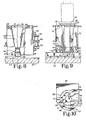
- Buckets 24A and 24B have been mentioned already with reference to Fig. 1A and these buckets are shown in the same locations in Fig. 7.
- the buckets are identical and there are twelve of them equally spaced along the chain 48.
- the chain is fastened to the bucket by a pair of L-shaped chain connector links 59 secured to the flat wall 61 of the bucket by a pair of socket head cap screws 62.
- Each of the twelve buckets is secured to the chain in the same way.
- Figs. 8 and 9 when viewed together, also show bucket support rollers 63, each of which is rotatably mounted to the bucket by a shoulder bolt or screw such as 64.
- Cam rollers suitable for this purpose can be purchased finished.
- the combination of these rollers, the drive chain and the walls 66 of the bottom slot 67 of the buckets provide guidance along guide tracks 42 for the buckets as they are moved along the straight flights of the conveyor chain.
- Each of the tracks 42 is tapered as at 42A (Fig. 7) at each end to facilitate entrance of the track into the guide groove 67 of a bucket as the bucket moves onto the track from either the front end or rear end. This is important becausq, as will be described, the servo motor can drive the conveyor in either direction.
- the tool receiver buckets have further important features according to the present invention.
- the significance of these features can be best appreciated if one recalls that the standard tool holder used in many machines with automatic tool changers includes- a gripper receiver flange with the groove such as 32 (Fig. lA) therein to receive the grippers of a tool changer.
- the tool holder also includes a conical portion or taper 27T receivable in a matching taper in the tool spindle.
- a retaining knob 27K which is typically in the form of a double truncated cone and which is engagable by the collet in the milling machine spindle such as the collet arms in Fig. 10 of the above mentioned Roch patent.
- each bucket has a shallow circular well 68 extending from the top surface 69 of the bucket down to a distance almost as great as the distance between the groove 32 and shank-end face 30S of the tool holder flange 30.
- this well extends slightly more than 180° about its axis.
- the axis of this well is colinear with the axis 71 of a. frustoconical surface 72 which extends downward from the bottom of the well to a pocket 73 which preferably has an open bottom.
- the front wall of the bucket is cut away to provide a large notch-shaped opening at 74.
- the wall edges 76 and 77 at the opening are sloped parallel to the slope of the conical surface 72. These wall edges are typically defined by planar surfaces and the parallelism can be best seen in Fig. 8 where it is noted that the wall edge 77 is perpendicular to the plane of the paper and parallel to the dotted line 72D representing the conical wall of the bucket. It should also be noted that the wall edges 76 and 77. are not quite tangent to the wall 72. Therefore, the width of the opening 74 is less than the diameter of the frustoconical space defined by wall 72 at all points throughout the height of the space.
- the opening 74 is divergent from the space outward to the outside of the bucket as best shown in Figs. 7 and 10.
- Intersections 76L and 77L are closer to each other than are intersections 76W and 77W.
- the above described features of the buckets enable reception and confinement of the gripper flange of the tool holder in the shallow well 68 of the bucket, and the collet receiver or pull knob 27K of the tool holder in the pocket 73 of the bucket.
- the slope of the wall 72 provides any guidance which may be needed upon insertion of the tool in the bucket by the fingers 33 and 34, but is of adequate diameter at all points that it does not at all snugly grip or laterally confine the tool holder in the bucket. Accordingly, the tool bolder is adequately confined at the top by its flange in the bucket well and at the bottom by its knob in the pocket 73.
- the above mentioned conventional tool holders have index notches, grooves, or slots in the circumferential grooved gripper flange thereof.
- the buckets are provided with index keys such as 81 (Fig. 10) in the notch 82 in the upper exterior wall of the bucket.
- index keys such as 81 (Fig. 10) in the notch 82 in the upper exterior wall of the bucket.
- Each of these keys projects slightly into the well 68 where it can be received in one of the two diametrically opposed keyways or index grooves in the tool holder.
- the key is provided with a pair of apertures receiving screws 83 by which it is secured to the bucket.
- the proximal end of finger 33 has a spur gear 84 shaped thereon (as by a gear shaper machine) for rotation about axis 33C on the gear block 36.
- finger 34 has a spur gear 86 at the proximal end thereof, for rotation on gear block 36 about the axis 34C.
- the gear block guidingly receives a "finger rack" 87 operatively engaged with the gear 84 to rotate it about axis 33C.
- the finger rack 87 is connected to an air valve and rack arm 88 by a cap screw 89 (Figs. 7 and 11), with a finger rack spacer sleeve 91 concentric with the screw and filling the space between the end 87E of the finger rack and the inner face 88F of the arm 88.
- the end of arm 88 opposite that secured to the screw 89 is connected to the end of a piston rod of a double acting air cylinder mounted in block 36, the mounting bolts for one of the cylinder heads being shown at 92 in Fig. 11.
- the piston rod axis is at 93 and hidden behind the end portion 90 of the arm 88. A full stroke of this piston in the piston extension direction opens the fingers to the positions shown in Figs. 1B and 7.
- the pivoting of the gear block 36 is achieved by driving a sprocket 94 (Fig. 7) secured to the shaft assembly 96 to which the gear block 36 is secured.
- This sprocket is driven by a chain 97 (Fig. lA), the lower portion of which, as well as the sprocket 94 are omitted from Fig. 1A to avoid unduly complicating that schematic drawing.
- the chain is driven by a sprocket 98 on the shaft of a rotary actuator 99 Figs. lA, 12 and 13 secured in the housing.
- the fingers must swing through an arc of 180° to move the tool holder from the position it has in a conveyor bucket, and the position it has in the spindle of the machine. Accordingly, where the sprocket sizes are the same at both ends of chain 27, the rotary actuator must have the capability of 180° of shaft drive. It was further mentioned above that, to remove a tool holder from a conveyor bucket, the fingers must move upward through an arc of 10°. This increases the total index requirement for the fingers to 190°: Therefore, if the rotary actuator shaft sprocket and gear block sprocket are of the same size, the rotary actuator stroke must be 190°.
- the sprocket sizes are selected such that the rotary actuator stroke is 270° for 190° of gear block rotation. This makes more torque available from a rotary actuator of a given size, to be able to rotate heavier tools. It will be apparent that some options are available, but this has proved to be very satisfactory and the description will proceed for this particular embodiment of the finger swing drive.
- the rotary actuator shaft 101 is provided with the sprocket 98 on one end and an index stop finger 102 secured by two set screws 103 tightened onto the opposite square end 101S of the shaft.
- the stop finger has a curved notch.104 (Fig. 14) therein for engagement with a finger gag 106 (Fig. 12) when the latter is projected in the direction of arrow 107 and the stop finger is rotating in the direction of arrow 38 (Figs. 2A and 14).
- the finger gag is secured to the piston rod of the double acting air cylinder 108 secured to a bracket 109 which is; in turn, secured to the housing as by cap screws 110.
- Bracket 109 includes a portion having a bushing 111 therein guidingly receiving the finger gag.
- a similar bushing 112 is secured in an aperture in bracket 109 and is aligned on the common axis of the piston rod, finger gag guide bushing 111 and bushing 112.
- This finger gag stops rotation of the finger in the direction of arrow 38 at a position where the tool holder gripper fingers are in a horizontal plane aligned with the tool holder receiver flange of a tool holder in a bucket in the load/unload position. If it were not for the finger gag, every actuation of the rotary actuator in the direction of arrow 38 would cause rotation of the fingers completely around to the attitude shown in Fig. 4A for insertion of a tool holder in or removal of a tool holder from the machine spindle.
- the bushing 112, receiving the finger gag when it is advanced by the air cylinder 108, provides the additional support desired for long life despite repeated impacts of the finger with the finger gag during operation of the rotary actuator.
- an indicator finger assembly 113 (Fig. 13) is keyed to the rotary actuator shaft 101 as is the sprocket 98.
- This includes three position-indicator fingers or posts 114, 116, and 117 circularly spaced on a ring 113 keyed and secured to the shaft 101 by a set screw.
- Three proximity sensor switches 119, 121, and 122 are mounted to this bracket.
- Post 114 and sensor switch 121 cooperate to signal the full index of the rotary actuator in a clockwise direction (Figs. lA, 3A, and 6A).
- Post 116 and switch 122 cooperate to signal a 10" counterclockwise rotation from full index, this being the point at which the finger gag, when extended, can stop the rotary actuator and thus stop the counterclockwise travel of the gripper fingers at the position shown in Fig. 2A for engaging or disengaging the grooved flange of a tool holder in a conveyor bucket.
- Post 117 and switch 119 cooperate upon a complete counterclockwise index of the rotary actuator whereupon the tool holder gripping fingers have reached the spindle load/unload position (Figs. 4A and 5A).
- a portion 126 (Figs. 1A and 7) of the housing mounting bracket is provided with a central aperture 127 and four bolt apertures 128 for securing directly to the bottom of a head 14 centered on the spindle axis 129.
- This particular bracket is precisely centered with respect to the plane 131 containing the axis of the spindle and the axis of the tool holder conveyor bucket which is positioned in the load/unload or transfer point of the tool changer.
- a sensor switch 132 mounted in the housing (Fig. 7). This switch responds to a button-head screw 133 (Figs. 8 and 10)_ in the outer wall of a certain bucket which, for control reference purposes, is designated as the "No. 1" bucket. This is used for reference purposes.
- the position of the conveyor is continuously updated by pulses from the shaft encoder 57 on the end of the conveyor drive servo motor as the motor operates in the forward or reverse direction to drive the conveyor in either direction.
- the tool holder bucket has an index key in it for reception in the index slot in the tool holder flange.
- the finger 33 has an index key 134 thereon which engages the index slot in the tool holder flange when the finger closes on the tool holder in the bucket. Accordingly, it maintains the correct index of the tool holder as it swings the tool holder up and out of the bucket, and then down and around and up into the spindle where a key in the spindle then engages a slot in the tool holder flange to properly index the tool with reference to the spindle.
- the housing is provided with a side cover 136 (Fig. lA).
- This is attached to the stationary portion of the housing by hinges 137 along the top.
- hinges 137 One long piano hinge or a series of hinges with aligned axes can be provided.
- This cover can be simply opened up in the direction of arrow 138 and rested on top of the stationary portion of the housing, as indicated by the dotted lines 136A shown in Fig. lA.
- a window can be provided in the side wall of this swingable housing cover.
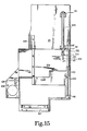
- a sliding door 139 is provided in the lower front of the housing.
- This housing bottom door has an edge-formed tube 141 therein slidingly and guidingly received on a guiderod 143 secured to the - bottom of the housing by a guiderod support bracket 144 secured to the bottom plate 23 and having a pair of apertured ears 146, 147 holding the guide rod in them.
- the other side of the door is slidably supported on a slide rail or support bar 148 closely spaced below and fastened by suitable brackets to the bottom 23 of the housing.
- the door is shown in the open position in the solid outline 139 in Fig. 15.
- a pneumatic cylinder 149 secured to the housing bottom 23 by a pair of end mounting brackets 151.
- a piston rod 152 has a clevis 153 pinned at 154 to a bracket 156 welded on the bottom of the door.
- the door is shut against a rubber bumper 157 by the same cylinder by applying air to the opposite end, it being a double acting pneumatic cylinder.
- The-bumper is mounted to the bottom flange at the inside front wall of the housing and extends slightly below the housing to provide a sufficiently high abutment surface for the front edge 139F of the chip door to reliably engage.
- this door is entirely covered by the housing, regardless of whether the door is open or shut. Therefore, there is no hazard to the operator during a tool change operation such as would exist if an outwardly swinging door were operated during a tool transfer between the storage magazine and spindle.
- EDM electrical discharge machining
Landscapes
- Engineering & Computer Science (AREA)
- Mechanical Engineering (AREA)
- Automatic Tool Replacement In Machine Tools (AREA)
Applications Claiming Priority (2)
| Application Number | Priority Date | Filing Date | Title |
|---|---|---|---|
| US40971082A | 1982-08-19 | 1982-08-19 | |
| US409710 | 1982-08-19 |
Publications (2)
| Publication Number | Publication Date |
|---|---|
| EP0103956A2 true EP0103956A2 (de) | 1984-03-28 |
| EP0103956A3 EP0103956A3 (de) | 1985-01-09 |
Family
ID=23621671
Family Applications (1)
| Application Number | Title | Priority Date | Filing Date |
|---|---|---|---|
| EP83304291A Withdrawn EP0103956A3 (de) | 1982-08-19 | 1983-07-25 | Automatischer Werkzeugwechsler mit kurvenförmiger Werkzeugbewegung |
Country Status (2)
| Country | Link |
|---|---|
| EP (1) | EP0103956A3 (de) |
| ES (1) | ES524534A0 (de) |
Cited By (5)
| Publication number | Priority date | Publication date | Assignee | Title |
|---|---|---|---|---|
| WO2002018094A3 (en) * | 2000-08-31 | 2002-06-27 | Hurco Co Inc | Tool changer for removal and installation of tools in a machining centre |
| US6641511B2 (en) | 2000-08-31 | 2003-11-04 | Hurco Companies, Inc. | Movable arm activated tool changer for machine tool system |
| EP1177053A4 (de) * | 1999-05-07 | 2009-01-14 | Designetics | Automatische grundierungsstation |
| CN107322227A (zh) * | 2017-08-22 | 2017-11-07 | 凯里市浪金科技有限责任公司 | 一种油箱焊接设备 |
| US10562119B2 (en) | 2014-05-15 | 2020-02-18 | General Electric Company | Machining system and tool holding apparatus thereof |
Family Cites Families (8)
| Publication number | Priority date | Publication date | Assignee | Title |
|---|---|---|---|---|
| FR1270076A (fr) * | 1960-07-12 | 1961-08-25 | G S P Atel | Machine-outil à changement automatique d'outils |
| US3608188A (en) * | 1969-01-22 | 1971-09-28 | Cincinnati Milacron Inc | Machine tool |
| CH548816A (de) * | 1970-09-04 | 1974-05-15 | Trumpf & Co | Werkzeugaufnahme. |
| US3998338A (en) * | 1972-08-31 | 1976-12-21 | Toyoda Machine Works, Limited | Automatic tool changing apparatus |
| DE2554052A1 (de) * | 1975-12-02 | 1977-06-08 | Hermann O Steinke | Kurzwegwechsel-werkzeugbefestigung fuer handhabungsautomatik |
| US4087901A (en) * | 1976-08-16 | 1978-05-09 | Kearney & Trecker Corporation | Tool change mechanism for machine tools |
| US4176991A (en) * | 1978-03-23 | 1979-12-04 | Egli Henry O | Hinged tool holder |
| GB2073624B (en) * | 1980-04-08 | 1983-02-16 | Newall Eng | Tool transfer mechanisms |
-
1983
- 1983-07-25 EP EP83304291A patent/EP0103956A3/de not_active Withdrawn
- 1983-07-28 ES ES524534A patent/ES524534A0/es active Granted
Cited By (6)
| Publication number | Priority date | Publication date | Assignee | Title |
|---|---|---|---|---|
| EP1177053A4 (de) * | 1999-05-07 | 2009-01-14 | Designetics | Automatische grundierungsstation |
| WO2002018094A3 (en) * | 2000-08-31 | 2002-06-27 | Hurco Co Inc | Tool changer for removal and installation of tools in a machining centre |
| US6494821B1 (en) | 2000-08-31 | 2002-12-17 | Hurco Companies, Inc. | Movable arm activated tool changer for machine tool system |
| US6641511B2 (en) | 2000-08-31 | 2003-11-04 | Hurco Companies, Inc. | Movable arm activated tool changer for machine tool system |
| US10562119B2 (en) | 2014-05-15 | 2020-02-18 | General Electric Company | Machining system and tool holding apparatus thereof |
| CN107322227A (zh) * | 2017-08-22 | 2017-11-07 | 凯里市浪金科技有限责任公司 | 一种油箱焊接设备 |
Also Published As
| Publication number | Publication date |
|---|---|
| EP0103956A3 (de) | 1985-01-09 |
| ES8405658A1 (es) | 1984-06-16 |
| ES524534A0 (es) | 1984-06-16 |
Similar Documents
| Publication | Publication Date | Title |
|---|---|---|
| US5093978A (en) | Manipulator for tools and tool adapters | |
| US6077206A (en) | Storage device for machine tools | |
| US5025690A (en) | Vertical spindle turret lathe | |
| US5031490A (en) | Process and equipment for loading and unloading the main work spindle of a lathe | |
| US3947951A (en) | Tool changer | |
| US4316398A (en) | Loading and/or unloading device for machine tools, particularly automatic lathes | |
| US5496249A (en) | Tool changer for a processing center | |
| JP3874872B2 (ja) | 主軸頭3軸移動型cnc旋盤 | |
| EP0103956A2 (de) | Automatischer Werkzeugwechsler mit kurvenförmiger Werkzeugbewegung | |
| JP2001105203A (ja) | 旋盤のシャフトワーク用ローダアンローダ | |
| US20030180137A1 (en) | Device for gripping and transporting workpieces in turning machines | |
| US3678572A (en) | Tool changer | |
| US3793708A (en) | Automatic cutting-tip replacing apparatus | |
| EP0003027B1 (de) | Automatischer Werkzeugwechsler für eine Werkzeugmaschine | |
| EP0254043B1 (de) | Einrichtung und Verfahren zum Bearbeiten von Werkstücken | |
| US5945009A (en) | Apparatus for processing workpieces by spark erosion | |
| EP0011710A1 (de) | Werkzeugmaschine mit automatischer Werkzeugwechselvorrichtung für Einzelwerkzeuge und Mehrspindelbohrköpfe, und ein Mehrspindelbohrkopf | |
| US4497410A (en) | Automatic tool changer for a lathe | |
| EP0541020B1 (de) | Maschine für gedruckte Schaltungen mit einem Werkzeugwechsler | |
| US5401230A (en) | Numerically controlled machine tool and machining method thereof | |
| US6205631B1 (en) | Machining center in which tool holders have a multiple coupling with a cover | |
| US6115895A (en) | Machining center in which tool holders have a coupling module and additionally a multiple coupling | |
| EP0994057B1 (de) | Vorrichtung zum Zuführen von Rollen aus Einschlagmaterial in einer Zigarettenverpackungsmaschine und Verfahren zum Aufnehmen und Transportieren dieser Rollen | |
| US6216325B1 (en) | Machining center with loading device having a pivot arm | |
| CN220516231U (zh) | 一种刀库断刀检测机构 |
Legal Events
| Date | Code | Title | Description |
|---|---|---|---|
| PUAI | Public reference made under article 153(3) epc to a published international application that has entered the european phase |
Free format text: ORIGINAL CODE: 0009012 |
|
| AK | Designated contracting states |
Designated state(s): CH DE FR GB IT LI |
|
| PUAL | Search report despatched |
Free format text: ORIGINAL CODE: 0009013 |
|
| AK | Designated contracting states |
Designated state(s): CH DE FR GB IT LI |
|
| STAA | Information on the status of an ep patent application or granted ep patent |
Free format text: STATUS: THE APPLICATION IS DEEMED TO BE WITHDRAWN |
|
| 18D | Application deemed to be withdrawn |
Effective date: 19850910 |
|
| RIN1 | Information on inventor provided before grant (corrected) |
Inventor name: SMITH, JOE A. |