EP0104019A1 - Compensation de défaut d'image - Google Patents
Compensation de défaut d'image Download PDFInfo
- Publication number
- EP0104019A1 EP0104019A1 EP83305156A EP83305156A EP0104019A1 EP 0104019 A1 EP0104019 A1 EP 0104019A1 EP 83305156 A EP83305156 A EP 83305156A EP 83305156 A EP83305156 A EP 83305156A EP 0104019 A1 EP0104019 A1 EP 0104019A1
- Authority
- EP
- European Patent Office
- Prior art keywords
- correction signal
- correction
- picture elements
- picture
- picture element
- Prior art date
- Legal status (The legal status is an assumption and is not a legal conclusion. Google has not performed a legal analysis and makes no representation as to the accuracy of the status listed.)
- Granted
Links
- 238000003702 image correction Methods 0.000 title claims description 7
- 238000012937 correction Methods 0.000 claims abstract description 204
- 238000012544 monitoring process Methods 0.000 claims abstract description 43
- 230000007547 defect Effects 0.000 claims abstract description 34
- 238000012545 processing Methods 0.000 claims abstract description 32
- 230000003252 repetitive effect Effects 0.000 claims abstract description 8
- 238000000034 method Methods 0.000 claims description 51
- 238000012360 testing method Methods 0.000 claims description 23
- 238000006073 displacement reaction Methods 0.000 claims description 10
- 239000011159 matrix material Substances 0.000 claims description 8
- 238000001514 detection method Methods 0.000 claims description 5
- 238000001914 filtration Methods 0.000 claims description 5
- 230000000694 effects Effects 0.000 abstract description 8
- 230000006870 function Effects 0.000 description 9
- 238000006243 chemical reaction Methods 0.000 description 6
- 238000010586 diagram Methods 0.000 description 5
- 230000003287 optical effect Effects 0.000 description 5
- 230000005686 electrostatic field Effects 0.000 description 4
- 238000005286 illumination Methods 0.000 description 2
- 230000000717 retained effect Effects 0.000 description 2
- 241000226585 Antennaria plantaginifolia Species 0.000 description 1
- 241000269913 Pseudopleuronectes americanus Species 0.000 description 1
- 230000000295 complement effect Effects 0.000 description 1
- 238000007796 conventional method Methods 0.000 description 1
- 230000007423 decrease Effects 0.000 description 1
- 230000003247 decreasing effect Effects 0.000 description 1
- 230000007812 deficiency Effects 0.000 description 1
- 230000006866 deterioration Effects 0.000 description 1
- 230000036039 immunity Effects 0.000 description 1
- 230000000977 initiatory effect Effects 0.000 description 1
- 238000011835 investigation Methods 0.000 description 1
- 238000012804 iterative process Methods 0.000 description 1
- 238000005259 measurement Methods 0.000 description 1
- 230000005855 radiation Effects 0.000 description 1
- 239000007787 solid Substances 0.000 description 1
- 230000002123 temporal effect Effects 0.000 description 1
Images


Classifications
-
- H—ELECTRICITY
- H04—ELECTRIC COMMUNICATION TECHNIQUE
- H04N—PICTORIAL COMMUNICATION, e.g. TELEVISION
- H04N5/00—Details of television systems
- H04N5/14—Picture signal circuitry for video frequency region
-
- H—ELECTRICITY
- H04—ELECTRIC COMMUNICATION TECHNIQUE
- H04N—PICTORIAL COMMUNICATION, e.g. TELEVISION
- H04N23/00—Cameras or camera modules comprising electronic image sensors; Control thereof
- H04N23/80—Camera processing pipelines; Components thereof
- H04N23/81—Camera processing pipelines; Components thereof for suppressing or minimising disturbance in the image signal generation
Definitions
- the present invention relates to image correction and is particularly applicable to image correction in television cameras.
- a television camera has an optical system which directs incident radiation onto a camera tube from which electronic signals are obtained.
- a number of phenomena occur for which correction is required if an acceptable quality television picture is to be produced.
- the number of phenomena requiring correction is considerably increased for colour television cameras.
- the signals are predetermined in accordance with mainly theorectical considerations.
- the corrections applied are calculated for a standard camera tube and therefore any deviation of a tube from the standard will cause a deterioration in performance.
- the present invention seeks to mitigate the above disadvantages.
- apparatus for correcting defects in an image having a plurality of picture elements comprising monitoring means for monitoring the value of a parameter from each of the picture elements, processing means for calculating a correction signal from the parameter values and control means for applying the correction signal to correct the image defects.
- a method of correcting defects in an image having a plurality of picture elements comprising measuring the value of a parameter at each of the plurality of picture elements, calculating a correction signal from the parameter values and applying the correction signal to correct image defects.
- One of the above described corrections relates to focus correction.
- the image viewed by a television camera is focussed with the camera tube by the generation of an axial magnetic field within the tube in conjunction with an electrostatic field.
- the magnetic field is set up by passing a current through a magnetic coil, referred to as a yoke, and an electrostatic field is set up by applying a voltage to a focussing electrode.
- a correction signal is applied to the camera tube electrostatic field in order to compensate for this lack of uniformity of focus.
- conventional correction signals are derived from mainly theoretical considerations and a standard predetermined correction signal is applied to the camera tube image. The resulting focus correction is frequently less than the optimum focus correction especially since each tube/yoke combination will have a slightly different maximum focus object plane of electro-beam focus correction.
- a preferred embodiment of the present invention provides focus correction apparatus for an electro-optical tube comprising monitoring means for measuring the optimum focus parameter value at each of a plurality of picture elements, processing means for calculating a correction signal from the measured values and control means for applying the correction signal to correct the focussing of images produced by the electro-optical tube.
- An associated embodiment of the present invention provides a method of focus correction for an electro-optical tube comprising the steps of measuring the optimum focus parameter value at each of a plurality of picture elements, calculating a correction signal from the measured values and applying the correction, signal to correct the focussing of images produced by the electro-optical tube.
- a preset range of focussing voltages is tested so as to identify the voltage which results in the maximum focus parameter value amplitude.
- the identified voltage represents the optimum focus for the picture element.
- the picture element signal is band pass filtered in order that the high frequency energy from the edge of the picture element is used for determining the maximum signal amplitude.
- a camera contains a number of camera tubes it is necessary for the tubes to have a common spatial registration.
- a colour television camera it is necessary for the three colour tubes to have a common spatial registration.
- Such a registration must be optimised in order to avoid blurring of the final image.
- apparatus for calculating relatively small errors in the spatial registration of an electro-optical tube comprising a reference generator which generates a plurality of reference picture elements, monitoring means which monitor the picture signals of the tube derived from said reference picture elements, comparator means which compare picture element and reference picture element signals, displacement means which, for each picture element, displaces the picture element in a first direction to a position of relativly large registration error, as measured by the comparator means, and which displaces the picture element in a direction opposite the first direction to a position of substantially the same relatively large registration error, as measured by the comparator means, and processing means for calculating, from the displacements effected by the displacement means, the position of optimum spatial registration and an error signal representing the initial error in spatial registration of the picture element.
- An associated embodiment of the present invention provides a method calculating relatively small errors in the spatial registration of an electro-optical tube comprising the steps of generating a plurality of reference picture elements, monitoring the picture element signals of the tube derived from said reference picture elements, comparing picture element and reference picture element signals, for each picture element displacing the picture element in a first direction to a position of relatively large registration error, displacing the picture element in a direction opposite the first direction to a position of substantially the same relatively large registration error and calculating, from the displacements effected, the position of optimum spatial registration and an error signal representing the intial error in spatial registration of the picture element.
- the displacement occurs in successively smaller steps until a minimum error is reached, in contrast to using displacements in opposite directions.
- the invention also provides apparatus for compensating spatial registration errors of an electro-optical tube comprising the above specified apparatus for correcting spatial registration errors together with processing means for calculating a correction signal from the measured picture element error signals and control means for applying the correction signal to compensate images produced by the tube for spatial registration errors of the tube.
- the invention also provides a method of compensating spatial registration errors of an electro-optical tube comprising the steps of the above specified method of correcting spatial registration errors together with the calculation of a correction signal from the measured picture element error signals and the application of the correction signal to compensate images produced by the tube for errors in the spatial registration of the tube.
- the vignetting of images produced by an electro-optical tube and correction thereof is known.
- Image vignetting is also present in some solid state image producing devices.
- the problem of vignetting is particularly noticable in images produced by devices such as colour television broadcast cameras.
- Each of the three colour camera tubes will produce a slightly different vignetting and the final image will exhibit colour shading.
- the vignetting produced by each camera tube is conventionally compensated by multiplying a correction signal by the camera tube output.
- the correction signal is usually of a simple parabolic waveform and although the resulting correction is acceptable this conventional method is tedious and must be undetaken by a skilled techician.
- a further embodiment of the present invention provides apparatus for correcting image vignetting comprising monitoring means for monitoring the signals from each of a plurality of picture elements, processing means for calculating a correction signal from the monitored signals and control means for applying the correction signal to correct vignetting of images.
- an associated aspect of the present invention provides a method of correcting image vignetting comprising the steps of monitoring the signals from each of a plurality of picture elements, calculating a correction signal from the monitored signals and applying the correction signal to correct vignetting of images.
- Bias lighting is provided for a camera tube so as to reduce lag when the camera tube image changes.
- the bias lighting does not correspond to flat field illumination and it is therefore necessary to correct the output of the camera tube to avoid shading in the final image.
- a further preferred embodiment of the invention therefor provides apparatus for correcting image black shading comprising monitoring means for monitoring the )signa1s produced by bias lighting from each of a plurality of pictures elements, comparator means for comparing each monitored signal with a reference to provide an error value for each picture element, processing means for calculating a correction signal from the error values and control means for applying the correction signal to correct images.
- the present invention there is provided a method of correcting black shading comprising the steps of monitoring the signals produced by bias lighting from each of a plurality of picture elements, comparing each monitored signal with a reference to provide an error value for each picture element, calculating a correction signal from the error values and applying the correction signal to correct images.
- Errors are introduced into the image produced by a television camera tube due to geometric phenomena of the camera.
- the errors can be caused by the geometry of the camera tube and/or scanner yoke iself. Further errors can be introduced by non-linearities of image scanning within the camera tube. Such errors in general are more prevalent towards the edges of the image.
- Geometric errors can be caused by non-linearities of scanning yoke current wave forms and by pin cushion or barrel distortion in image scanning.
- image correction apparatus Eor correcting errors in the image produced by an electro-optical tube due to geometric phenomena comprising monitor means for monitoring the value of a parameter from each of a plurality of picture elements, processing means for calculating a correction signal from the parameter values and control means for applying the correction signal to correct images produced by the electro-optical tube.
- a further preferred embodiment of the present invention provides a method of correcting errors in the image produced by an electro-optical tube due to geometric phenomena comprising the steps of monitoring the valve of a parameter from each of a plurality of picture elements calculating a correction signal from the parameter values and applying the correction signal to correct images produced by the electro-optical tube.
- the optical arrangement of a camera lens can introduce defects in an image produced by a camera tube. Such defects are a particular problem in situations where the focal length of the camera lens is varied, either by changing lenses or by the use of zoom lenses. Zoom lenses used with television broadcast cameras can establish focal length ratios of up to 42:1. Such dramatic changes in focal length are, of course, accompanied by equally dramatic changes in the angle of view and such changes in the angle of view can severely aggravate defects in the image produced by the camera tube. Lateral chromatic abberation defects which vary with focal length also present an important problem to be solved.
- Another embodiment of the present invention provides apparatus for correcting camera lens produced defects in an image produced by a camera tube comprising monitoring means for monitoring a parameter value for each of a plurality of picture elements, processing means for calculating a correction signal from the parameter values, control means for applying the correction signal to correct image defects and scaling means for scaling the correction signal in accordance with variations of focal length of the camera lens.
- calculation of the correction signal involves a feedback configuration.
- a first correction is applied and its effect monitored.
- the correction is adjusted, if necessary, and a repetitive sequence undertaken until the optimum correction is obtained.
- An associated embodiment consists of a method of correcting camera lens produced defects in an image produced by a camera tube comprising monitoring a parameter valve for each of a plurality of picture elements, calculating a correction signal from the parameter values, applying the correction signal to correct image defects and scaling the correction signal in accordance with variations of focal length of the camera lens.
- calculation of the correction signal includes multiplying each of two adjacent picture element error signals by a respective reference signal, the reference signals being in anti-phase with each other and being equal in frequency to half the frequency of occurrence of the picture elements whose error signals are being multiplied and summing the multiplied signals, whereby calculation of the correction signal includes a smoothed interpolation.
- This smoothed interpolation can advantageously be realised using the scaling characteristics of digital to analog converters.
- the particular feature of the image to be corrected is selected.
- the correction apparatus is set so as to measure the relevant correction parameter value.
- the correction parameter value is then measured from each of a plurality of picture elements.
- the precise method of measuring the correction parameter value depends upon the correction being made, but will usually include comparison of a signal from each picture element with a respective reference signal.
- test chart is located in front of the camera.
- the test chart contains a regular matrix of 15 rows and 15 columns of rectangular picture areas.
- the picture areas are identical and are simply areas of small white rectangles on a black background.
- the value of the relevant parameter is measured from the signal produced by each of the picture areas on the test card.
- the measured values are converted to digital form in order to facilitate subsequent processing.
- a circuit for monitoring valves from the picture elements may include gate location of the individual picture elements, analogue processing of the gated video, analogue to digital conversion and storage in a RAM under the control of a CPU.
- the RAM stored values can be interpolated in real time to provide a correction signal which is applied for real time correction of the image defects.
- a correction signal is calculated from the correction parameter values. In calculating the required correction signal it is necessary to process line and field data simultaneously.
- the line rate is of the order of 10's of KHz and the field rate seldom exceeds a few hundred hertz.
- Low pass filtering is possible for line data but is not simultaneously possible for field data since such filtering would result in the loss of information from the line data. It is therefore necessary to use an interpolation technique.
- Interpolation of the correction parameter values in can be implemented utilizing the scaling function of digital to analog converters. Other interpolation techniques may be used.
- Each correction parameter value, in digital form, from a pair of adjacent field data picture elements is multiplied by a respective reference signal.
- the reference signal's have a frequency equal to half the frequency of occurrence of field picture elements and the reference signals are in anti-phase with each other.
- the multiplied values are summed and thereby provide a smoothed interpolation.
- Figure 1 illustrates the field rate interpolation of information.
- Two reference signals are provided, V REF.1 and V REF.2.
- the frequency of the reference signals is half the frequency of occurance of the picture elements whose valves are being multiplied.
- V REF.l and V REF.2 vary, in this example, linearly between maxima and minima and are in anti-phase with each other.
- V REF.1 has a value of V
- V.ef.2 has a value of 0.
- V REF.l decreases to 0 while V REF.2 increases to V. Consequently, when the interpolation is mid-way between the two values the situation will be as depicted by time B in Figure 1.
- the output signal will be equal to V/2 X (value 1 + value 2). Having completely traversed from the first picture element to the second picture element, the signals will be as depicted at time C in Figure 1. The output signal is now equal to V x value 2. The process is then repeated between value 2 and the next value, value 3. The temporal position of value 3 is represented by D in Figure 1.
- FIG. 2 A circuit for implementing the interpolation illustrated by Figure 1 is shown in Figure 2.
- the interpolation utilises the scaling function of digital to analog converters.
- Two digital to analog converters 2 and 4 are provided.
- V REF.1 is applied to an input of the converter 2 and
- V HEF.2 is applied to an input the converter 4.
- value 1 is applied to an input of converter 2
- value 2 is applied to an input of converter 4.
- Outputs from the converters 2 and 4 are applied to a summing circuit 6.
- the value applied to each digital to analog converter 2 and 4 is changed when he respective reference signal, V REF.1 or V REF.2, reaches 0. Consequently, referring to Figure 1, at time C the value applied to converter 2 is changed from value 1 to value 3. Similarly, at time D the value applied to converter 4 is changed from value 2 to value 4 the fourther correction parameter value.
- D/A 1 carries the values corresponding to row 1 of samples, while D/A 2 has the values for row 2.
- D/A 1 carries the values corresponding to row 1 of samples
- D/A 2 has the values for row 2.
- the output from D/A 1 is reduced while the output from D/A 2 is increased.
- This produces a crossfade between the two convertor outputs thus providing vertical interpolation.
- D/A 1 is loaded with the correction data for row 3 and the corssfade procedure is repeated with D/A 2 output decreasing as D/A 1 output increases.
- the effect of samples more than one row apart on the final analogue waveform is taken care of by iterative correction routines as described later.
- a test chart consisting of a matrix of fifteen rows and fifteen columns of identical rectangular white areas on a black background is provided for use in focus correction.
- Focus correction is carried out for each individual camera tube of which there may be a number, for example in a colour television broadcast camera.
- the focussing of a camera tube requires correction due to the fact that the camera tube image provides a uniform focus for a curved object plane. This defect is produced by well known phenomena and obviously requires correction. Conventionally, a predetermined correction signal has been applied to the camera tube electrostatic field, but such correction signals have been determined from theoretical considerations or by the trial and error application of correction signals. This invention provides a correction signal which is calculated from the optimum focus parameter value at each of a plurality of picture elements.
- a camera tube is manually focussed on the test chart.
- a picture element signal is produced by the camera tube and is applied to the focus correction apparatus 10 shown in Figure 3.
- the focus correction apparatus 10 comprises monitoring means 12 for measuring the optimum focus parameter value at each of the picture elements, processing means 14 for calculating a correction signal from the measured values and control means 16 for applying the correction signal to correct the electon beam focussing of the camera tube image.
- the camera tube image signal is passed to the input 18 of the measuring circuit 12.
- the circuit 12 includes a gate circuit 20 which is responsive to the video signal of the picture element viewed by the camera and thus the picture area provided by the test chart. Gate location of the picture element with the picture area is undertaken prior to the initiation of the measuring sequence.
- the gated video signal is passed from the gate unit 20 to a band pass unit 22.
- the band pass unit 22 filters the picture element signal so that only the high frequency energy, presented in the video information of the picture area under investigation, is used for further processing.
- the filtered picture element signal is passed to a peak detector 24.
- the peak detector 24 detects the peak-to-peak amplitude of the filtered picture element signal.
- a sample and hold unit 26 receives peak-to-peak amplitude data from detector 24 and the units 20 to 26 constitute the measuring circuit 12.
- the voltage applied to the tube focussing electrode 28 is increased in steps over a preset range of voltages.
- the peak-to-peak amplitude is detected by the detector 24 and is passed to the sample and hold unit 26 and thus to be CPU which retains a record of which of the focus electrode voltages resulted in the maximum peak-to-peak amplitude of the picture element signal.
- the gate control is progressed so as to coincide with the next picture area of the test chart, until all the 225 locations or areas are tested.
- the values for focus are then compared to a previous pass and a correction is output to increase the focus at each location. The process is repeated until optimum focus is achieved in all locations.
- the processing means 14 includes an analog to digital converter 30, a CPU 32, a RAM 34 and a digital to analog converter 36.
- the signal passed from the sample and hold unit 26 of the measuring circuit 12 is in analog form. That signal is converted by the analog to digital converter 30 and the digital information is stored in the RAM 34 under the control of the CPU.32.
- the RAM 34 Under control of the CPU 32 the RAM 34 stores information relating to the signal received from each of the picture elements.
- the RAM 34 in effect stores the correction signal necessary to compensate the camera tube image so as to simulate a flat object plane of uniform focus.
- the real time application of the correction values stored in the RAM 34 to the focussing electrode voltage is inconvenient. Consequently, it is necessary to provide an interpolation of the value storage in RAM 34 in order to effect real time correction of the focussing electrode voltage.
- the digital-to-analog unit 36 is used to provide a smoothed interpolation in the manner described above with reference to Figures 1 and 2.
- the signal derived from interpolation by unit 36 is applied to the modulator 16 which is interposed between the focus voltage supply 38 and the focussing electrode 28.
- Unit 36 modulates the supplied focus voltage in accordance with the interpolated signal from unit 36 so that the voltage received by the focussing electrode 28 is fully corrected, whereby optimum focussing of the camera tube image is provided.
- Interpolation of the value stored in RAM 34 utilises the scaling function of digital to analog converters.
- the values from two adjacent picture elements are each multiplied by a respective reference signal and the multiplied values are summed. Multiplication of the values from RAM 34 is undertaken in the manner explained with the aid of Figure 1.
- the interpolation is effected by the circuitry shown in Figure 2 which corresponds to the digital to analog unit 36 of Figure 3.
- the test chart consists of a regular matrix of fifteen rows and fifteen columns of identical rectangular white areas on a black background. Each of the white area acts as a reference picture element.
- a correction signal is provided for each of the camera tubes and since the process is the same for each tube a detailed description will be given with respect to one tube only.
- the image produced by the camera tube is divided into 225 picture elements each of which should be in registration with a respective picture area of the test chart. For each of the picture elements in turn, the picture element signal is measured and is compared with the reference picture element. It will be appreciated that the reference picture elements are provided by the output of the reference tube, usually the green channel.
- An error signal is generated corresponding to the error of registration between the picture element signal and the reference picture element.
- Figure 4 illustrates variation of the error signal 40.
- a circuit for monitoring values from the picture elements may include gate location of the individual picture elements, registration error detector, analogue to digital conversion and storage in a RAM under the control of a CPU.
- the RAM stored values can be interpolated in real time to provide a correction signal which is applied for real time correction of the image defects.
- Interpolation of the picture element error values in this embodiment of the present invention may utilise the scaling function of digital to analogue converters. Such an interpolation is described above with reference to Figures 1 and 2 of the drawings.
- vignetting produced by the individual camera tubes In a colour television camera it is particularly necessary to correct vignetting produced by the individual camera tubes in order to avoid colour shading being exhibited by the final image.
- the vignetting produced by the three colour camera tubes is unique for each colour.
- a software generated flat field reference is compared with the actual video signal from each camera tube and the required correction signal for that tube is calculated.
- the correction signal is then applied to the output of the camera tube so that all images produced by the tube are corrected for vignetting.
- a circuit for monitoring values from the picture elements may include gate location of the individual picture elements, sample and hold of the video level, analogue to digital conversion and storage in a RAM under the control of a CPU.
- the RAM stored valves can be interpolated in real time to provide a correction signal which is applied for real time correction of the image defects.
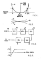
- Figure 5 illustrates the vignetting of a camera tube image and illustrates the required correction signal.
- the uncorrected image produced by a camera tube is represented by the line 50 which is curvilinear as opposed to the linear desired output 52.
- the curvilinear form of signal 50 is manifest as a darkening towards the edge of the image. This is the common phenomenon of vignetting which along with some tube and prism defects is also referred to in respect of colour television cameras as black and white shading.
- a correction signal illustrated by the phantom line 54 must be added to the camera tube signal 50 so as to produce the desired output signal 52.
- the correction signal 14 is the complement of the signal 50.
- the correction signal 54 is provided in the following manner.
- the video signal is monitored for each of a pluraltiy of picture elements of the camera tube image. These picture element signals are each compared with a respective reference picture element signal forming part of the software generated flat field reference. Using the error values obtained from the comparison of each picture element with its reference, the correction signal 54 is calculated. A feedback configuration is sued and the correction signal calculated in a repetitive sequence until the comparison reveals no error.
- the picture element signals are provided by the diascope within the camera tube and an external image is not therefore required to generate the picture elements.
- the Black Shading detector integrates the whole of the sample area and produces a dc level to the A/D convertor which corresponds to the video level present at the location.
- the analogue correction waveform being updated and applied to the video processing amplifier before the sample point, thus the effect of the correction will be monitored on successive passes.
- This iterative process enables the generated correction waveform to evolve step by step, until the correction waveform exactly offsets the black shading present. In this way black shading can be corrected to better than 0.5% of peak white, both absolutely and differentially, as measured after Gamma correction.
- the diascope pattern is again used and the video level measured by a peak detector. This dc level is A/D converted for use by a Microprocessor. Again multiple passes are used with the correction waveform steadily developing until an exact fit is obtained to the nearest increment of the value stored in memory.
- White Shading errors can be reduced to less than 1% after Gamma correction both absolutely and differentially by the technique.
- the camera has a routine to allow the difference between an externally illuminated flat field as seen through the lens and the diascope field to be stored and used to modify the results subsequently obtained with the diascope.
- FIG. 6 A simplified block diagram is given in Figure 6 in order to illustrate the apparatus for monitoring the picture element signals and calculating the correction signal.
- the video signal from each picture element is applied in turn to the input 60.
- Each video signal is processed by a sample and hold unit 62 and subsequently passed to an analog to digital converter 64.
- the digital signals are passed to a CPU 66 under the control of which they are stored in a RAM 68.
- the values stored in the RAM 68 are interpolated so as to form the correction signal 54. Interpolation is undertaken using the scaling function of digital to analog converter in a digital to analog unit 70.
- the interpolation includes multiplying error values, in digital form, from each of two adjacent picture elements by respective reference signals.
- the multiplied values are summed and a smoothed interpolation is provided.
- the unit 70 is formed of the circuit of Figure 2 and the interpolation is carried out as described with reference to Figures 1 and 2.
- the camera tubes of a colour television camera are supplied with bias lighting which reduces the lag which the tubes would otherwise exhibit in responding to the change in images viewed by the camera.
- the bias lighting does not represent a flat field and will consequently introduce shading in the final image unless correction is undertaken.
- the colour television camera is set for operation but the lens cap is retained on the camera lens. Consequently,' only the bias lighting is available for producing an output signal from the camera tubes. For each of the tubes a correction value is calculated to compensate for the fact that the bias lighting does not present a flat field. These correction signals are stored and applied to the output from the camera tubes during normal operation of the camera, so as to avoid shading in the final image being caused by the bais lighting. Only bias lighting is required within the camera and any diascope is switched off.
- a circuit for monitoring values from the picture elements may include gate location of the individual picture elements, sample and hold of the video level, analogue to digital conversion and storage in a RAM under the control of a CPU.
- the RAM stored values can be interpolated in real time to provide a correction signal which is applied for real time correction of the image defects.
- the correction of camera tube black shading comprises monitoring the signals produced by the bias lighting from each of a plurality of picture elements, comparing each monitored signal with a reference to provide an error value for each picture element, calculation of a correction signal from the error values and application of the correction signal so as to correct images produced by the camera tube.
- a feedback configuration is used in a repetitive sequence until no error is detected by the comparison.
- the reference is software generated and interpolation is necessary in calculating the correction signal.
- Coventional interpolation techniques used in data processing utilise complex software. Such software can be expensive, difficult to maintain and will sometimes produce discontinuities in interpolation.
- Interpolation of the error values in this embodiment of the invention can utlise the scaling function of digital to analog converters. Such an interpolation is described above with reference to Figures 1 and 2.
- Errors are introduced into the image produced by a television camera tube due geometric phenomena of the camera. Such phenomena include geometry of the camera tube itself and non-linearities of image scanning within the camera tube. Automatic correction of such errors may be provided by this invention.
- Image correction is achieved by monitoring picture element signals from an object, generating elemental signals of the desired image, comparing corresponding picture element and elemental signals, calculating a correction signal from said comparison and applying the correction signal to correct images produced by the camera tube.
- a test chart containing a regular matrix of fifteen rows and fifteen columns of rectangular picture areas is located in front of the camera.
- the picture areas are identical and are simply rectangular areas of white on a black back ground.
- Geometric correction may normally be considered to be the registration of green video to an electronic reference.
- the picture elements are then scanned and the signal from each picture element is stored for processing. It should be appreciated that these stored values will include accumulative errors caused by the various geometric phenomena produced within the camera.
- a circuit for monitoring valves from the picture elements may include gate location of the individual picture elements, geometry/registration detection, analogue to digital conversion and storage in a RAM under the control of a CPU.
- the RAM stored values can be interpolated in real time to provide a correction signal which is applied for real time correction of the image defects.
- a reference generator generates elemental signals of the desired image which is, of course , an exact replica of the test chart. Corresponding picture element and elemental signals are compared by a comparator which generates a difference signal for each of the picture elements.
- the difference signals represent the accumulative geometric errors.
- a correction signal is calculated from the difference signals and is applied so as to correct images produced by the camera tube.
- a feedback configuration is used in a repetitive sequence until a minimum error is measured for all areas. Calculation of the correction signal is undertaken by processing means which utilise interpolation between adjacent difference signals. Control means are provided for storing the correction signal and applying the correction signal so as to correct images produced during normal operation of the camera tube.
- Interpolation of the difference signals by the processing means utilises the scaling function of digital to analog converters. Difference values from adjacent picture elements are multiplied by a respective reference signal and the multiplied values are summed.
- the interpolation used is that described above with reference to Figures 1 and 2 of the drawings.
- the measurement and correction techniques are the same for both geometry and registration errors.
- the output of the green channel and an electronically generated version of the test pattern, which is taken as the reference are compared location by location, first for vertical error detection and correction and then for horizontal detection and correction.
- the reference itself is switched through the detectors such that any errors in the detectors will be automatically compensated for.
- Errors are detected by addressing the detector to each location in turn and determining what polarity of correction is required. Starting from a mid point value, the memory location for each sample is then incremented or decremented according to the sense of correction required. After each complete pass of the test pattern the memory values are read out and converted to an analogue waveform as previously described and applied to all three scan amplifiers to modify the scanning current waveforms. The procedure is then repeated until all locations are corrected to less than one increment of accuracy. To speed up the process the size of correction increments is large for the early passes and reduced as the routine proceeds. By this method the geometry of the green channel can be corrected to better than 0.1%. This figure of course excludes the lens geometry.
- the same routine is used for correction registration errors, except the reference is now the green channel, instead of the electronic reference and the correction waveform is applied to the Red or Blue scan amplifiers only, as appropriate. Registration to better than 0.05% of picture ehight, over the entire picture area is achieved using this method.
- the camera has a routine to enable it to "learn" the difference in errors. Having registered with the diascope, the camera is pointed at an optical chart having the same pattern as the diascope slide. The optimum distance between lens and chart is used, as specified by the lens manufacturer. The automatic routine is then repeated to register the camera under these conditions.
- correction factor The difference between the two sets of correction data is stored as a correction factor, which is then used to modify all subsequent line ups from the diascope.
- Correction factors for several lens types can be held in memory at the same time, as a coding system is used to enable the camera to recognise which type of lens is in current use.
- the optical arrangement of a camera lens can introduce defects in the image produced by a camera tube. Such defects are particularly problematic where the focal length of the lens is varied, either by changing the lens or by using a zoom lens.
- a zoom lens may have a focal length ratio of 42:1.
- Such drastic changes in focal length are, of course, accompanied by equally drastic changes in the field of view.
- Such changes severely aggravate the defects introduced into the camera tube image.
- Lateral chromatic abberation is also a particularly important problem for colour television broadcast cameras utilising zoom lenses of high focal length ratios.
- the image signal from each of a plurality of picture elements is measured.
- the picture element signals are each compared with a single or respective elemental reference so as to provide an error value for each picture element.
- the error values are stored in digital form and are interpolated to provide the correction signal.
- the picture elements may be generated by positioning a test chart in front of the camera.
- the test chart contains a regular matrix of fifteen rows and fifteen columns of identical rectangular areas of white shading on a black background.
- a circuit for monitoring values from the picture elements may include gate location of the individual picture elements, geometry/registration detection, analogue to digital conversion and storage in a RAM under the control of a CPU.
- the RAM stored values can be interpolated in real time to provide a correction signal which is applied for real time correction of the image defects.
- Interpolation of the error values in this embodiment of the present invention can utilise the scaling function of digital to analog converters. Such an interpolation is described above with reference to Figures 1 and 2 of the drawings.
- automatic image of the above embodiments automatic image correction is provided.
- Such correction may, in each case, use a feedback configuration whereby a correction is obtained, its effect monitored and repetitive adjustment undertaken until the optimum result is obtained.
- V REF.1 and V REF.2 may have a non-linear form.
Landscapes
- Engineering & Computer Science (AREA)
- Multimedia (AREA)
- Signal Processing (AREA)
- Color Television Image Signal Generators (AREA)
Priority Applications (1)
| Application Number | Priority Date | Filing Date | Title |
|---|---|---|---|
| AT83305156T ATE23933T1 (de) | 1982-09-09 | 1983-09-06 | Bildfehlerkorrektur. |
Applications Claiming Priority (14)
| Application Number | Priority Date | Filing Date | Title |
|---|---|---|---|
| GB8225704 | 1982-09-09 | ||
| GB08225707A GB2132057B (en) | 1982-09-09 | 1982-09-09 | Electro-optical image correction |
| GB08225701A GB2126824B (en) | 1982-09-09 | 1982-09-09 | Camera tube compensation for varations of camera lens focal length |
| GB8225709 | 1982-09-09 | ||
| GB8225701 | 1982-09-09 | ||
| GB8225707 | 1982-09-09 | ||
| GB08225706A GB2126827B (en) | 1982-09-09 | 1982-09-09 | Electro-optical tube registration |
| GB08225709A GB2126829B (en) | 1982-09-09 | 1982-09-09 | Image correction |
| GB8225706 | 1982-09-09 | ||
| GB08225710A GB2126855B (en) | 1982-09-09 | 1982-09-09 | Focus correction |
| GB08225705A GB2126826B (en) | 1982-09-09 | 1982-09-09 | Correction of image vignetting |
| GB8225710 | 1982-09-09 | ||
| GB8225705 | 1982-09-09 | ||
| GB08225704A GB2126825B (en) | 1982-09-09 | 1982-09-09 | Black shading correction |
Publications (2)
| Publication Number | Publication Date |
|---|---|
| EP0104019A1 true EP0104019A1 (fr) | 1984-03-28 |
| EP0104019B1 EP0104019B1 (en) | 1986-11-26 |
Family
ID=27562683
Family Applications (1)
| Application Number | Title | Priority Date | Filing Date |
|---|---|---|---|
| EP83305156A Expired EP0104019B1 (en) | 1982-09-09 | 1983-09-06 | Image correction |
Country Status (1)
| Country | Link |
|---|---|
| EP (1) | EP0104019B1 (fr) |
Cited By (1)
| Publication number | Priority date | Publication date | Assignee | Title |
|---|---|---|---|---|
| GB2356514A (en) * | 1999-09-09 | 2001-05-23 | Pandora Int Ltd | Film defect correction |
Citations (4)
| Publication number | Priority date | Publication date | Assignee | Title |
|---|---|---|---|---|
| DE2636209A1 (de) * | 1975-09-02 | 1977-03-10 | Hughes Aircraft Co | Vorrichtung zur verbesserung der qualitaet eines gerasterten bildes |
| DE3107042A1 (de) * | 1980-02-25 | 1981-12-24 | Ampex Corp., 94063 Redwood City, Calif. | Verfahren und vorrichtung zur gesamtrasterfehlerkorrektur fuer die automatische einstellung einer fernsehkamera o.dgl. |
| DE3114888A1 (de) * | 1980-04-14 | 1982-03-04 | Ampex Corp., 94063 Redwood City, Calif. | Verfahren und vorrichtung zum korrigieren von raum- und abschattungsfehlern von farbfernsehkameras |
| US4320414A (en) * | 1979-04-27 | 1982-03-16 | Tokyo Shibaura Denki Kabushiki Kaisha | Adjusting device for color television camera apparatus |
-
1983
- 1983-09-06 EP EP83305156A patent/EP0104019B1/en not_active Expired
Patent Citations (4)
| Publication number | Priority date | Publication date | Assignee | Title |
|---|---|---|---|---|
| DE2636209A1 (de) * | 1975-09-02 | 1977-03-10 | Hughes Aircraft Co | Vorrichtung zur verbesserung der qualitaet eines gerasterten bildes |
| US4320414A (en) * | 1979-04-27 | 1982-03-16 | Tokyo Shibaura Denki Kabushiki Kaisha | Adjusting device for color television camera apparatus |
| DE3107042A1 (de) * | 1980-02-25 | 1981-12-24 | Ampex Corp., 94063 Redwood City, Calif. | Verfahren und vorrichtung zur gesamtrasterfehlerkorrektur fuer die automatische einstellung einer fernsehkamera o.dgl. |
| DE3114888A1 (de) * | 1980-04-14 | 1982-03-04 | Ampex Corp., 94063 Redwood City, Calif. | Verfahren und vorrichtung zum korrigieren von raum- und abschattungsfehlern von farbfernsehkameras |
Non-Patent Citations (1)
| Title |
|---|
| PHILIPS TECHNISCHE RUNDSCHAU, vol. 38, no. 11/12, 1979, Eindhoven A. HOYER, M. SCHLINDWEIN "Bild-verbesserung durch digitale Nach-verarbeitung" pages 311-323 * |
Cited By (3)
| Publication number | Priority date | Publication date | Assignee | Title |
|---|---|---|---|---|
| GB2356514A (en) * | 1999-09-09 | 2001-05-23 | Pandora Int Ltd | Film defect correction |
| GB2356514B (en) * | 1999-09-09 | 2004-04-07 | Pandora Int Ltd | Film restoration system |
| US7012642B1 (en) | 1999-09-09 | 2006-03-14 | Pandora International Limited | Method for adjusting digital images to compensate for defects on film material |
Also Published As
| Publication number | Publication date |
|---|---|
| EP0104019B1 (en) | 1986-11-26 |
Similar Documents
| Publication | Publication Date | Title |
|---|---|---|
| EP0460947B1 (fr) | Appareil de correction d'image | |
| JP2861333B2 (ja) | 画像補正装置 | |
| US8654240B2 (en) | Optical chromatic aberration correction and calibration in digital cameras | |
| EP0083176B1 (fr) | Système et dispositif pour la conversion de signaux vidéo en images sur un support d'enregistrement sensible à la lumière | |
| US5532765A (en) | Image correction apparatus using a displayed test signal | |
| US4099092A (en) | Television display alignment system and method | |
| US4999703A (en) | Automatic image correction method and apparatus for projectors utilizing cathode ray tubes | |
| US4733296A (en) | Multi-tube color TV camera in which linear and non-linear components of a registration error due to chromatic aberration of a lens are corrected with corresponding deflection correction signals | |
| JP2001525640A (ja) | 1つまたは2つ以上のプロジェクタを調節するための方法および装置 | |
| US7457458B1 (en) | Method and apparatus for defining and correcting image data | |
| US3757161A (en) | Television camera geometric distortion correction system | |
| US5414330A (en) | Cathode ray tube control apparatus | |
| US4731652A (en) | Shading correction signal generating device for a television camera apparatus | |
| US6002434A (en) | Registration correction waveform determination method and system for a television camera | |
| US5896170A (en) | Dynamic alignment of cathode ray tube rasters | |
| EP0104019A1 (fr) | Compensation de défaut d'image | |
| JP2001197332A (ja) | 画像再生システムの欠陥を判定し且つ少なくとも部分的に補正する方法及び該方法を実施するための装置 | |
| US4823188A (en) | Apparatus for correcting for shading defects in video signals induced by variations in the speed of scanning spots in a TV camera | |
| JPS5965811A (ja) | 対物レンズに依存する非直線歪及び位置ずれを補正する方法 | |
| JPH06327019A (ja) | 画像補正装置 | |
| JPH07131742A (ja) | 投射型ディスプレイの画像補正装置 | |
| JPS5970086A (ja) | 像補正方法及び装置 | |
| JP3402788B2 (ja) | ディジタルコンバーゼンス装置 | |
| GB2126855A (en) | Focus correction | |
| JPH05145935A (ja) | 画像補正装置 |
Legal Events
| Date | Code | Title | Description |
|---|---|---|---|
| PUAI | Public reference made under article 153(3) epc to a published international application that has entered the european phase |
Free format text: ORIGINAL CODE: 0009012 |
|
| AK | Designated contracting states |
Designated state(s): AT BE CH DE FR GB IT LI LU NL SE |
|
| 17P | Request for examination filed |
Effective date: 19840227 |
|
| GRAA | (expected) grant |
Free format text: ORIGINAL CODE: 0009210 |
|
| PUAC | Information related to the publication of a b1 document modified or deleted |
Free format text: ORIGINAL CODE: 0009299EPPU |
|
| STAA | Information on the status of an ep patent application or granted ep patent |
Free format text: STATUS: THE APPLICATION HAS BEEN WITHDRAWN |
|
| AK | Designated contracting states |
Kind code of ref document: B1 Designated state(s): AT BE CH DE FR GB IT LI LU NL SE |
|
| REF | Corresponds to: |
Ref document number: 23933 Country of ref document: AT Date of ref document: 19861215 Kind code of ref document: T |
|
| DB1 | Publication of patent cancelled | ||
| 18W | Application withdrawn |
Withdrawal date: 19861013 |
|
| EN | Fr: translation not filed | ||
| GBPC | Gb: european patent ceased through non-payment of renewal fee | ||
| RIN1 | Information on inventor provided before grant (corrected) |
Inventor name: LITTLEJOHN, HUGH KENDAL Inventor name: GROVES, PHILIP RANGECROFT |