EP0104020A2 - Manipulation et/ou traitement de bande continue en mouvement et procédé ou/et appareil d'enroulement et de formage en relief d'une telle bande - Google Patents
Manipulation et/ou traitement de bande continue en mouvement et procédé ou/et appareil d'enroulement et de formage en relief d'une telle bande Download PDFInfo
- Publication number
- EP0104020A2 EP0104020A2 EP83305200A EP83305200A EP0104020A2 EP 0104020 A2 EP0104020 A2 EP 0104020A2 EP 83305200 A EP83305200 A EP 83305200A EP 83305200 A EP83305200 A EP 83305200A EP 0104020 A2 EP0104020 A2 EP 0104020A2
- Authority
- EP
- European Patent Office
- Prior art keywords
- web
- drum
- reel
- roller
- suction
- Prior art date
- Legal status (The legal status is an assumption and is not a legal conclusion. Google has not performed a legal analysis and makes no representation as to the accuracy of the status listed.)
- Withdrawn
Links
Images


Classifications
-
- B—PERFORMING OPERATIONS; TRANSPORTING
- B29—WORKING OF PLASTICS; WORKING OF SUBSTANCES IN A PLASTIC STATE IN GENERAL
- B29C—SHAPING OR JOINING OF PLASTICS; SHAPING OF MATERIAL IN A PLASTIC STATE, NOT OTHERWISE PROVIDED FOR; AFTER-TREATMENT OF THE SHAPED PRODUCTS, e.g. REPAIRING
- B29C59/00—Surface shaping of articles, e.g. embossing; Apparatus therefor
- B29C59/02—Surface shaping of articles, e.g. embossing; Apparatus therefor by mechanical means, e.g. pressing
- B29C59/04—Surface shaping of articles, e.g. embossing; Apparatus therefor by mechanical means, e.g. pressing using rollers or endless belts
-
- B—PERFORMING OPERATIONS; TRANSPORTING
- B29—WORKING OF PLASTICS; WORKING OF SUBSTANCES IN A PLASTIC STATE IN GENERAL
- B29B—PREPARATION OR PRETREATMENT OF THE MATERIAL TO BE SHAPED; MAKING GRANULES OR PREFORMS; RECOVERY OF PLASTICS OR OTHER CONSTITUENTS OF WASTE MATERIAL CONTAINING PLASTICS
- B29B13/00—Conditioning or physical treatment of the material to be shaped
- B29B13/02—Conditioning or physical treatment of the material to be shaped by heating
- B29B13/023—Half-products, e.g. films, plates
-
- B—PERFORMING OPERATIONS; TRANSPORTING
- B65—CONVEYING; PACKING; STORING; HANDLING THIN OR FILAMENTARY MATERIAL
- B65H—HANDLING THIN OR FILAMENTARY MATERIAL, e.g. SHEETS, WEBS, CABLES
- B65H20/00—Advancing webs
- B65H20/12—Advancing webs by suction roller
-
- B—PERFORMING OPERATIONS; TRANSPORTING
- B65—CONVEYING; PACKING; STORING; HANDLING THIN OR FILAMENTARY MATERIAL
- B65H—HANDLING THIN OR FILAMENTARY MATERIAL, e.g. SHEETS, WEBS, CABLES
- B65H23/00—Registering, tensioning, smoothing or guiding webs
- B65H23/04—Registering, tensioning, smoothing or guiding webs longitudinally
- B65H23/18—Registering, tensioning, smoothing or guiding webs longitudinally by controlling or regulating the web-advancing mechanism, e.g. mechanism acting on the running web
- B65H23/195—Registering, tensioning, smoothing or guiding webs longitudinally by controlling or regulating the web-advancing mechanism, e.g. mechanism acting on the running web in winding mechanisms or in connection with winding operations
-
- B—PERFORMING OPERATIONS; TRANSPORTING
- B65—CONVEYING; PACKING; STORING; HANDLING THIN OR FILAMENTARY MATERIAL
- B65H—HANDLING THIN OR FILAMENTARY MATERIAL, e.g. SHEETS, WEBS, CABLES
- B65H23/00—Registering, tensioning, smoothing or guiding webs
- B65H23/04—Registering, tensioning, smoothing or guiding webs longitudinally
- B65H23/24—Registering, tensioning, smoothing or guiding webs longitudinally by fluid action, e.g. to retard the running web
Definitions
- THIS INVENTION relates generally to the handling and/or processing of a continuous, moving web. More particularly, the invention relates to a method of and apparatus for winding up a continuous, moving web. Also, more particularly, the invention relates to a method of and apparatus for embossing a continuous, moving web.- Also, more particularly, the invention relates to a rotary drum for use in transporting a continuous, moving web.
- Existing surface wind-up mechanisms comprise a driven wind-up drum around which a web to be wound up passes. From the wind-up drum the web passes onto a core to form a reel. The reel is urged against the wind-up drum so that rotation of the drum causes rotation of the reel.
- the tightness with which the web is wound up on the reel also referred to as the bulk density of the reel, depends on the force with which the reel is urged against the drum. The greater the force, the greater the bulk density.
- the traversing cutter which is normally used to cut the web when changing over from a completed reel to a new core.
- the traversing cutter is normally located upstream of the wind-up drum.
- the speed at which it traverses the web has to be sufficiently low in relation to the speed of forward movement of the web so that that side where cutting commences has had time to reach the new core and become attached to that core before the cutter has reached the other side of the web.
- This leads to an oblique cut which extends at an angle substantially less than 90° to the direction of movement of the web, and hence long end portions on each reel which cannot normally be used by the end user and have to be discarded.
- the web tends to adhere to the embossing roller and, in existing embossing equipment, tension has to be applied to pull it away from the roller. Failure to pull the web away from the roller under sufficient tension leads to a condition known as 'wrap-around' which, if it has occurred, requires the apparatus to be shut down, the damaged portion of the web to be cut away, the web to be rejoined and the apparatus to be re-started. In view of the considerable loss in production time and material which this would lead to, the tendency is to run the apparatus at web tensions which are generally higher than they need be at any particular time.
- a method of increasing/decreasing the frictional adherence of the web to the drum, or assisting separation of the web from the drum comprising having the drum provided with a plurality of perforations leading to the surface of the drum, and applying suction/pressure to the web through the perforations.
- the drum may be internally divided into at least two circumferentially spaced sectors, the suction/pressure differing from one said sector to the other. Suction may be applied to one said sector and pressure to the other.
- Pressure or neither suction nor pressure, may be applied to the web via said perforated surface in the region where the reel is urged against the wind-up drum.
- the new core may be brought into the same circumferential position as previously occupied by the completed reel.
- the web may be cut in at least two stages, namely a first stage in which a plurality of longitudinally spaced cuts which together extend across the entire width of the web are made, and a second stage in which a plurality of longitudinally extending cuts are made which interconnect the longitudinally spaced cuts.
- the web may be cut.by means of a traversing cutter which traverses the full width of the web in a time less than that required for the web to travel from the cutter to the new core.
- a method of changing reels which comprises:
- a method of embossing a continuous, moving web in which the web passes through the nip between an embosser roller and a counter bole, and in which the embossed web is then stripped from the embosser roller by means of a stripper roller, the method comprising :
- Said perforated surface may be formed by a material which is resiliently deformable to a substantiall greater extent than that to which the material of the embosser roller is deformable.
- a rotary drum for use in transporting a continuous, moving web, the drum being hollow and having a plurality of perforations leading from the hollow interior of the drum to the outer surface thereof, and there being partitioning in the hollow interior which divides the hollow interior into at least two circumferentially spaced chambers, the drum being rotatable with respect to the partitioning.
- apparatus for transporting a continuous, moving web comprising a rotary drum as defined above, and a pump connected to one of said chambers to apply either suction or pressure to that chamber.
- a suction inlet of the pump may be connected to one of said chambers to apply suction to that chamber, and a delivery outlet of the pump connected to the other chamber to apply pressure to that other chamber.
- a wind-up mechanism for winding up a continuous, moving web comprising:
- the drum may be hollow, there being provided partitioning in the hollow interior of the drum, the partitioning dividing the hollow interior into at least two circumferentially spaced chambers and the drum being rotatable with respect to the partitioning.
- the partitioning may be displaceable about the axis of rotation of the drum.
- embossing apparatus for embossing a continuous, moving web, the apparatus comprising :
- the outer surface of the stripper roller may be formed by a material which is resiliently deformable to a substantially greater extent than that to which the material of the embosser roller is deformable.
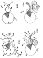
- reference numeral 10 generally indicates a surface wind-up mechanism which comprises a wind-up drum 12, a lay-on roller 14, and a turret 16.
- the turret is mounted on a carriage (not shown) and is rotatable with respect to the carriage about an axis 18 parallel to the axis of rotation of the drum 12.
- the carriage is displaceable towards or away from the drum 12, and a pneumatic or hydraulic cylinder 20 is provided for urging the turret towards the drum in the direction of arrow A.
- the turret 16 carries three replaceable cores 22 in a freely rotatable manner.
- the wind-up drum 12 is hollow and has a perforated outer surface 24.
- partitioning 26 which divides the interior of the drum into two circumferentially spaced chambers namely a pressure chamber 28 (shown shaded) and a suction chamber 30.
- the wind-up drum 12 is rotatable with respect to the partitioning 26.
- a pump 32 is provided which has its suction connected to the suction chamber 30, and its delivery to the pressure chamber 28.
- the turret 16 is restrained from rotating about the axis 18.
- rotation is permitted, as will be described in more detail later.
- a continuous, moving web 34 of a material such as pvc or a pvc/fabric laminate is attached adhesively to a new core, i.e. the one which, in Figure 1, is shown in position against the drum 12.
- the method of attachment will be described in more detail later.
- the drum is driven in the direction of arrow B (clockwise) and the core 22 in question urged against the drum by means of the cylinder 20. Engagement of the core 22 with the drum 12 will cause the core to rotate in an anti-clockwise direction and the web 34 to be reeled up on the core 22 to form a reel 23 (see Figure 2).
- the pressure applied to the pressure chamber 28, tends to cause separation of the web 34 from the surface of the wind-up drum, so that, from the beginning of the pressure chamber 28, the web can start contracting, thereby causing release of any strain set up in it as a result of tension in the web immediately upstream of the lay-on roller 14.
- the release of strain in webs of plastics material such as PVC is not immediate. It takes a certain amount of time.
- the eventual tightness or bulk density of the reel 23 depends essentially on two factors, namely on the residual strain in the web upon being wound up on the reel, and on the force with which the reel is urged against the drum. Tightness as a result of the first factor arises from the web tending to contract slowly after it has been wound up as a result of the residual strain slowly being released. Tightness as a result of the second factor arises because the reel generally has a diameter which is smaller than that of the wind-up drum. Pressure of the reel against the drum causes the reel to be compressed to form a concave portion on the reel, which concave portion has a radius of curvature corresponding to that of the drum.
- the concave portion Upon release of the pressure, the concave portion reverts to a convex shape having a radius of curvature corresponding to that of the reel at that point.
- the web As the latter radius of curvature is generally smaller than the former radius of curvature, the web is effectively stretched to a certain extent. The greater the force applied by the cylinder 20, the greater this effect.
- a constant tension of the web on the reel from immediately adjacent the core to the surface of the completed reel, can be obtained by suitably adjusting the angle C and the force applied by the cylinder 20 as the diameter of the reel increases.
- the cylinder 20 is retracted, allowing the new core to move around the drum in the direction of arrow G ( Figure 4) and the completed reel to move away from the drum in the direction of arrow H ( Figure 4).
- the new core will now occupy the position previously occupied by the completed reel and the process as described above will repeat itself.
- the completed reel can now be unloaded from the turret 16 and a new core loaded onto the turret in its place.
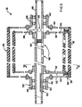
- the drum comprises a pair of hubs 40, a perforated cylindrical wall 42, and side walls 44 extending between the hubs and the cylindrical wall.
- the hubs 40 house ball bearings 46 whereby the drum is rotatable on a hollow shaft 48.
- the shaft 48 itself is pivotal about its axis (i.e. the axis of rotation of the drum 12) by being mounted in plummer blocks (not shown). This will allow for adjustment of the partitioning 26 in the direction of arrows D (see Figure 1) in order to change the angle C as hereinbefore described.
- the left hand hub 40 is provided with a key way 50 whereby drive gear (not shown) can be connected to the drum in order to drive the drum.
- the perforated surface 24 referred to in Figures 1 to 4 may be provided by the cylindrical wall 42 itself.
- the wall 42 may be provided with relatively large perforations, the perforated surface being formed by an outer liner having relatively small perforations communicating with the perforations in the wall 42.
- the lining may, for example, be formed by a sheet of elastomeric material such as silicone rubber which has been provided with a large number of pin-hole perforations.
- it may be formed by a sheet of fabric material. It could even be of metal, such as a finely woven metal fibre sheet or a layer of porous, sintered metal if the drum is to be used in a high temperature environment.
- the partitioning 26 in the interior of the drum 12 comprises two axially spaced cheek plates 52 which are keyed to the shaft 48, and two circumferentially spaced partition plates 54, the plates 52 and 54 together with the inside surface of the cylindrical wall 42 defining the pressure chamber 28 referred to earlier.
- the remainder of the interior of the drum 12 forms the suction chamber 30 referred to earlier.
- the tube 56 can be pressurised via a connection 60 and a pipe 62. When the tube 56 is pressurised, it exerts pressure against the sealing member 58, urging the sealing member into sealing engagement with the inner cylindrical surface of the cylindrical wall 42.
- the interior of the hollow shaft 48 is divided in two by means-of a plug 64.
- the interior of the hollow shaft 48 is in communication with the pressure chamber 28 by means of openings 66 in the side of the shaft, whereas, on the right hand side of the plug 64, the interior of the shaft is in communication with the suction chamber by means of openings 68 in the side of the shaft.
- the pump 32 ( Figure 1) will have its suction connected to the right hand side of the shaft 48 and its delivery to the left hand side of the shaft.
- reference numeral 70 generally indicates a cutting mechanism.
- the cutting mechanism comprises two longitudinally spaced punching devices 72.1 and 72.2.
- the punching device 72.1 is adapted to punch a transversely extending row of holes 74.1 in the web 34
- the punching device 72.2 is adapted to punch a transversely extending row of holes 74.2 in the web.
- the holes 74.1 and 74.2 together extend across the entire width of the web, but the holes 74.1 are spaced longitudinally from the holes 74.2 so that that part of the web ahead of the holes 74.1 remains attached to that part of the web behind the holes 74.2 (the direction of movement of the web being indicated by arrow J in Figure 8).
- a guide 82 is provided to guide the tongues 80.2 onto the drum 12.
- the longitudinal distance between the openings 74.1 and 74.2 is such that the leading ends of the tongues 80.2 will have reached the drum 12 and become attached thereto through suction before the circular cutters 76 have reached the openings 74.2. This will prevent separation between the leading and trailing ends of the web.
- An adhesive applying roller 84 is arranged to apply adhesive to the web, in the region between the holes 74.1 and 74.2, as this part of the web moves with the drum 12 to the beginning of the pressure chamber 28.
- adhesive is required only on the tongues 80.2, it does not matter that adhesive is also applied to the tongues 80.1 as the force with which the web is wound onto the nearly completed reel 23 is sufficient to tear the tongues 80.1 from the new core 22.
- the tongues 80.2 will, however, immediately become attached to the new core 22 and ensure that the leading end of the web is taken up on the new core.
- the punching devices 72.1 and 72.2 may be omitted and the circular cutters 72 replaced by a single, traversing cutter.
- a traversing cutter may be mounted on a carriage which is arranged to traverse the width of the web and, by engagement with the lay-on roller 14, cut the web across its entire width.
- the resulting cut will be at an angle of less than 90 0 to the direction of movement of the web, the angle depending on the speed of movement of the cutter in relation to the speed of movement of the web.
- the leading and trailing ends of the web will not separate. This permits a relatively high speed of transverse movement of the cutter ensuring a transverse cut which is relatively close to 90 0 to the direction of movement of the web.
- the carriage on which the transverse cutter is mounted may be provided with a brush which is effective to guide the web ends around the lay-on roller 14 onto the drum 12.
- FIG 9 there is shown a system of cutting wherein, instead of holes being punched into the web as indicated in Figure 8, short, transversely extending cuts 86.1 and 86.2 are made. As with the embodiment illustrated in Figures 7 and 8, longitudinally extending cuts are subsequently made along dotted lines 78 by transversely spaced circular cutters 76.
- the drum 12 may carry a cutting device, such as a blade or heated wire normally accommodated in a recess in its cylindrical surface, the cutting device being brought into operation by causing it to protrude from the recess. This will enable a cut extending at 90° to the direction of web movement to be effected.
- a cutting device such as a blade or heated wire normally accommodated in a recess in its cylindrical surface
- reference numeral 90 generally indicates an embosser comprising an embosser roller 92, a counter bole 94, and a stripper roller 96.
- a web 98 to be embossed is heated and fed downwardly into a nip formed between the embosser roller 92 and the counter bole 94.
- the web moves around the embosser roller 92 through a further nip formed between the embosser roller and the stripper roller 96.
- the stripper roller has a construction similar to that described with reference to Figures 5 and 6, although, in its application in an embosser, the perforated surface is preferably formed by a relatively thick outer liner of silicone rubber.
- the embosser roller will usually be of steel.
- the perforations in the silicone liner may be such that they form circumferentially extending slots, at the outer surface. The length of the slots should be slightly shorter than the circumferential length for which the stripper roller 96 remains in contact with the embosser roller 92.
- the length of contact is about 2 cm
- the length of the slots could be about 1 cm.
- the partitioning 26 (see Figure 1) and the way in which the pump 32 is connected, is arranged such that suction is applied only across a relatively narrow sector of the stripper roller 96, i.e. the sector diagrammatically indicated by shading at 100 in Figure 10.
Landscapes
- Engineering & Computer Science (AREA)
- Mechanical Engineering (AREA)
- Physics & Mathematics (AREA)
- Thermal Sciences (AREA)
- Shaping Of Tube Ends By Bending Or Straightening (AREA)
- Replacement Of Web Rolls (AREA)
- Winding Of Webs (AREA)
- Controlling Rewinding, Feeding, Winding, Or Abnormalities Of Webs (AREA)
Applications Claiming Priority (2)
| Application Number | Priority Date | Filing Date | Title |
|---|---|---|---|
| ZA826633 | 1982-09-09 | ||
| ZA826633 | 1982-09-09 |
Publications (2)
| Publication Number | Publication Date |
|---|---|
| EP0104020A2 true EP0104020A2 (fr) | 1984-03-28 |
| EP0104020A3 EP0104020A3 (fr) | 1986-06-11 |
Family
ID=25576266
Family Applications (2)
| Application Number | Title | Priority Date | Filing Date |
|---|---|---|---|
| EP83305198A Expired EP0104811B1 (fr) | 1982-09-09 | 1983-09-07 | Procédé et dispositif pour gaufrer et contrôler la tension d'une feuille continue en mouvement |
| EP83305200A Withdrawn EP0104020A3 (fr) | 1982-09-09 | 1983-09-07 | Manipulation et/ou traitement de bande continue en mouvement et procédé ou/et appareil d'enroulement et de formage en relief d'une telle bande |
Family Applications Before (1)
| Application Number | Title | Priority Date | Filing Date |
|---|---|---|---|
| EP83305198A Expired EP0104811B1 (fr) | 1982-09-09 | 1983-09-07 | Procédé et dispositif pour gaufrer et contrôler la tension d'une feuille continue en mouvement |
Country Status (3)
| Country | Link |
|---|---|
| EP (2) | EP0104811B1 (fr) |
| JP (2) | JPS59118654A (fr) |
| DE (1) | DE3370771D1 (fr) |
Cited By (6)
| Publication number | Priority date | Publication date | Assignee | Title |
|---|---|---|---|---|
| FR2617467A1 (fr) * | 1987-06-30 | 1989-01-06 | Coopelin | Dispositif tournant de distribution et de transfert pneumatique de produits divers souples |
| WO1996036549A3 (fr) * | 1995-05-15 | 1997-02-20 | Reumert Jens | Appareil pour fournir des longueurs individuelles predeterminees d'une bande d'un materiau |
| DE10322519A1 (de) * | 2003-05-19 | 2004-12-09 | Voith Paper Patent Gmbh | Bahnführungseinrichtung |
| DE10322521A1 (de) * | 2003-05-19 | 2004-12-23 | Voith Paper Patent Gmbh | Bahnführungs- und/oder Dichtungseinrichtung |
| CN116177276A (zh) * | 2023-04-27 | 2023-05-30 | 昆明天谋科技有限公司 | 一种锂铜复合带的卷放装置 |
| CN117682360A (zh) * | 2024-02-04 | 2024-03-12 | 杭州新天元织造有限公司 | 一种功能性涤纶面料表面整理后面料打卷运输系统及方法 |
Families Citing this family (4)
| Publication number | Priority date | Publication date | Assignee | Title |
|---|---|---|---|---|
| JPS6194961A (ja) * | 1984-10-15 | 1986-05-13 | Mitsubishi Paper Mills Ltd | シ−ト状物のル−プ制御方法 |
| GB8527661D0 (en) * | 1985-11-08 | 1985-12-11 | Ici Plc | Catalyst supports & precursors |
| US5211879A (en) * | 1989-11-07 | 1993-05-18 | Nippon Mining Co., Ltd. | Ester compounds and liquid crystal compositions containing the same |
| US5778724A (en) * | 1995-09-07 | 1998-07-14 | Minnesota Mining & Mfg | Method and device for monitoring web bagginess |
Family Cites Families (12)
| Publication number | Priority date | Publication date | Assignee | Title |
|---|---|---|---|---|
| US2526318A (en) * | 1948-02-10 | 1950-10-17 | Us Rubber Co | Sheet finishing apparatus |
| US3313002A (en) * | 1965-08-04 | 1967-04-11 | Du Pont | Apparatus for heat treating sheet material |
| US3586565A (en) * | 1968-12-04 | 1971-06-22 | Sealed Air Corp | Method and apparatus for the manufacture of cellular and laminated materials |
| CA965920A (en) * | 1970-01-06 | 1975-04-15 | E. I. Du Pont De Nemours And Company | Embossed polyester film preparation |
| JPS5229012Y2 (fr) * | 1972-07-19 | 1977-07-02 | ||
| US3950480A (en) * | 1973-01-12 | 1976-04-13 | Ethyl Corporation | Method for embossing plastic material |
| US3894827A (en) * | 1973-03-28 | 1975-07-15 | Ethyl Corp | Method and apparatus for embossing plastic film |
| DE2359121B2 (de) * | 1973-11-27 | 1976-12-02 | Alkor GmbH, 8000 München; CIBA-GEIGY AG, Basel (Schweiz) | Verfahren zur herstellung von gepraegten folien oder folienlaminaten |
| DE2456767A1 (de) * | 1974-11-30 | 1976-08-12 | Dynamit Nobel Ag | Verfahren und vorrichtung zur oberflaechenbearbeitung von bahnmaterial |
| US3969565A (en) * | 1975-03-26 | 1976-07-13 | Norman Forrest | Card clothing method for treating thermoplastic sheet material |
| US4259286A (en) * | 1979-05-04 | 1981-03-31 | The Procter & Gamble Company | Method and apparatus for texturing a thermoplastic film |
| DE3100814A1 (de) * | 1981-01-13 | 1982-07-29 | Günter O. 7432 Urach Stumpf | Vorgabewalze |
-
1983
- 1983-09-07 DE DE8383305198T patent/DE3370771D1/de not_active Expired
- 1983-09-07 EP EP83305198A patent/EP0104811B1/fr not_active Expired
- 1983-09-07 EP EP83305200A patent/EP0104020A3/fr not_active Withdrawn
- 1983-09-09 JP JP58165328A patent/JPS59118654A/ja active Pending
- 1983-09-09 JP JP58165329A patent/JPS59118644A/ja active Pending
Cited By (10)
| Publication number | Priority date | Publication date | Assignee | Title |
|---|---|---|---|---|
| FR2617467A1 (fr) * | 1987-06-30 | 1989-01-06 | Coopelin | Dispositif tournant de distribution et de transfert pneumatique de produits divers souples |
| WO1989000143A1 (fr) * | 1987-06-30 | 1989-01-12 | Coopelin | Dispositif tournant de distribution et de transfert pneumatique de produits divers souples |
| WO1996036549A3 (fr) * | 1995-05-15 | 1997-02-20 | Reumert Jens | Appareil pour fournir des longueurs individuelles predeterminees d'une bande d'un materiau |
| US6328245B1 (en) | 1995-05-15 | 2001-12-11 | Jens Reumert | Apparatus for dispensing individually predetermined lengths of a web material |
| DE10322519A1 (de) * | 2003-05-19 | 2004-12-09 | Voith Paper Patent Gmbh | Bahnführungseinrichtung |
| DE10322521A1 (de) * | 2003-05-19 | 2004-12-23 | Voith Paper Patent Gmbh | Bahnführungs- und/oder Dichtungseinrichtung |
| CN116177276A (zh) * | 2023-04-27 | 2023-05-30 | 昆明天谋科技有限公司 | 一种锂铜复合带的卷放装置 |
| CN116177276B (zh) * | 2023-04-27 | 2023-07-07 | 昆明天谋科技有限公司 | 一种锂铜复合带的卷放装置 |
| CN117682360A (zh) * | 2024-02-04 | 2024-03-12 | 杭州新天元织造有限公司 | 一种功能性涤纶面料表面整理后面料打卷运输系统及方法 |
| CN117682360B (zh) * | 2024-02-04 | 2024-04-23 | 杭州新天元织造有限公司 | 一种功能性涤纶面料表面整理后面料打卷运输系统及方法 |
Also Published As
| Publication number | Publication date |
|---|---|
| EP0104811B1 (fr) | 1987-04-08 |
| EP0104020A3 (fr) | 1986-06-11 |
| EP0104811A1 (fr) | 1984-04-04 |
| DE3370771D1 (en) | 1987-05-14 |
| JPS59118644A (ja) | 1984-07-09 |
| JPS59118654A (ja) | 1984-07-09 |
Similar Documents
| Publication | Publication Date | Title |
|---|---|---|
| CA1310310C (fr) | Methode et appareil de separation et de bobinage automatiques d'un materiau en bande | |
| US4327877A (en) | Winding device | |
| US3552670A (en) | Web winding apparatus | |
| US4529141A (en) | Method and apparatus for rewinding, severing and transferring web-like material | |
| RU2078731C1 (ru) | Способ наматывания листового материала в рулоны без сердечника и устройство для его осуществления | |
| EP0067051B1 (fr) | Procédé et appareil pour enrouler des bandes | |
| CA1073424A (fr) | Bloc de sortie de machine de traitement de trames, telles que machines a imprimer, etc. | |
| US6494398B1 (en) | Rewinding method and machine for making logs of paper and the like | |
| EP0104020A2 (fr) | Manipulation et/ou traitement de bande continue en mouvement et procédé ou/et appareil d'enroulement et de formage en relief d'une telle bande | |
| US5312059A (en) | Machine for rewinding and intermediately processing thin flexible material using a conveyor | |
| KR20010110431A (ko) | 웹 리와인더 촙-오프 및 이송 조립체 | |
| US3433429A (en) | Film winding apparatus | |
| KR19990021906A (ko) | 종이 웨브 감기용 감기 장치 | |
| FI82211B (fi) | Foerfarande och anordning foer framstaellning av armeringsskikt foer foerstaerkta gummiprodukter. | |
| US3383062A (en) | Method and apparatus for continuously winding web material with constant tension | |
| WO1995015901A1 (fr) | Procede et appareil de changement de lot dans un enrouleur de papier | |
| US3218894A (en) | Cutting rolled thermoplastic sheet | |
| US4854520A (en) | Apparatus for forming center-unwindable rolls of perforated plastic film | |
| KR19990022223A (ko) | 무심 접착 테이프 권취 맨드럴 및 방법 | |
| US3850713A (en) | Device for manufacturing articles having a non-woven pile | |
| US3977627A (en) | Winding and slitting apparatus | |
| US2414739A (en) | Combination ribbing and slitting machine | |
| CN103213867A (zh) | 宽幅卷材分切装置及分切方法 | |
| CN202558346U (zh) | 宽幅卷材分切装置 | |
| US3545494A (en) | Forming tube for glass fibers |
Legal Events
| Date | Code | Title | Description |
|---|---|---|---|
| PUAI | Public reference made under article 153(3) epc to a published international application that has entered the european phase |
Free format text: ORIGINAL CODE: 0009012 |
|
| AK | Designated contracting states |
Designated state(s): BE CH DE FR GB IT LI NL SE |
|
| PUAL | Search report despatched |
Free format text: ORIGINAL CODE: 0009013 |
|
| AK | Designated contracting states |
Kind code of ref document: A3 Designated state(s): BE CH DE FR GB IT LI NL SE |
|
| 17P | Request for examination filed |
Effective date: 19861209 |
|
| 17Q | First examination report despatched |
Effective date: 19870514 |
|
| STAA | Information on the status of an ep patent application or granted ep patent |
Free format text: STATUS: THE APPLICATION HAS BEEN WITHDRAWN |
|
| 18W | Application withdrawn |
Withdrawal date: 19870826 |
|
| RIN1 | Information on inventor provided before grant (corrected) |
Inventor name: LE MAITRE, RICHARD BRUCE CARLYLE |