EP0104148A2 - Gerät zum Erhalten eines elektrischen Signals in Verbindung mit der Position einer Quecksilbermasse in Instrumenten - Google Patents
Gerät zum Erhalten eines elektrischen Signals in Verbindung mit der Position einer Quecksilbermasse in Instrumenten Download PDFInfo
- Publication number
- EP0104148A2 EP0104148A2 EP83830159A EP83830159A EP0104148A2 EP 0104148 A2 EP0104148 A2 EP 0104148A2 EP 83830159 A EP83830159 A EP 83830159A EP 83830159 A EP83830159 A EP 83830159A EP 0104148 A2 EP0104148 A2 EP 0104148A2
- Authority
- EP
- European Patent Office
- Prior art keywords
- tube
- mercury
- sensor
- mass
- section
- Prior art date
- Legal status (The legal status is an assumption and is not a legal conclusion. Google has not performed a legal analysis and makes no representation as to the accuracy of the status listed.)
- Granted
Links
Images

Classifications
-
- G—PHYSICS
- G01—MEASURING; TESTING
- G01D—MEASURING NOT SPECIALLY ADAPTED FOR A SPECIFIC VARIABLE; ARRANGEMENTS FOR MEASURING TWO OR MORE VARIABLES NOT COVERED IN A SINGLE OTHER SUBCLASS; TARIFF METERING APPARATUS; MEASURING OR TESTING NOT OTHERWISE PROVIDED FOR
- G01D5/00—Mechanical means for transferring the output of a sensing member; Means for converting the output of a sensing member to another variable where the form or nature of the sensing member does not constrain the means for converting; Transducers not specially adapted for a specific variable
- G01D5/12—Mechanical means for transferring the output of a sensing member; Means for converting the output of a sensing member to another variable where the form or nature of the sensing member does not constrain the means for converting; Transducers not specially adapted for a specific variable using electric or magnetic means
- G01D5/14—Mechanical means for transferring the output of a sensing member; Means for converting the output of a sensing member to another variable where the form or nature of the sensing member does not constrain the means for converting; Transducers not specially adapted for a specific variable using electric or magnetic means influencing the magnitude of a current or voltage
- G01D5/20—Mechanical means for transferring the output of a sensing member; Means for converting the output of a sensing member to another variable where the form or nature of the sensing member does not constrain the means for converting; Transducers not specially adapted for a specific variable using electric or magnetic means influencing the magnitude of a current or voltage by varying inductance, e.g. by a movable armature
- G01D5/2006—Mechanical means for transferring the output of a sensing member; Means for converting the output of a sensing member to another variable where the form or nature of the sensing member does not constrain the means for converting; Transducers not specially adapted for a specific variable using electric or magnetic means influencing the magnitude of a current or voltage by varying inductance, e.g. by a movable armature by influencing the self-induction of one or more coils
- G01D5/202—Mechanical means for transferring the output of a sensing member; Means for converting the output of a sensing member to another variable where the form or nature of the sensing member does not constrain the means for converting; Transducers not specially adapted for a specific variable using electric or magnetic means influencing the magnitude of a current or voltage by varying inductance, e.g. by a movable armature by influencing the self-induction of one or more coils by movable a non-ferromagnetic conductive element
-
- G—PHYSICS
- G01—MEASURING; TESTING
- G01F—MEASURING VOLUME, VOLUME FLOW, MASS FLOW OR LIQUID LEVEL; METERING BY VOLUME
- G01F1/00—Measuring the volume flow or mass flow of fluid or fluent solid material wherein the fluid passes through a meter in a continuous flow
- G01F1/05—Measuring the volume flow or mass flow of fluid or fluent solid material wherein the fluid passes through a meter in a continuous flow by using mechanical effects
- G01F1/34—Measuring the volume flow or mass flow of fluid or fluent solid material wherein the fluid passes through a meter in a continuous flow by using mechanical effects by measuring pressure or differential pressure
- G01F1/36—Measuring the volume flow or mass flow of fluid or fluent solid material wherein the fluid passes through a meter in a continuous flow by using mechanical effects by measuring pressure or differential pressure the pressure or differential pressure being created by the use of flow constriction
-
- G—PHYSICS
- G01—MEASURING; TESTING
- G01K—MEASURING TEMPERATURE; MEASURING QUANTITY OF HEAT; THERMALLY-SENSITIVE ELEMENTS NOT OTHERWISE PROVIDED FOR
- G01K5/00—Measuring temperature based on the expansion or contraction of a material
- G01K5/02—Measuring temperature based on the expansion or contraction of a material the material being a liquid
- G01K5/16—Measuring temperature based on the expansion or contraction of a material the material being a liquid with electric contacts
-
- G—PHYSICS
- G01—MEASURING; TESTING
- G01L—MEASURING FORCE, STRESS, TORQUE, WORK, MECHANICAL POWER, MECHANICAL EFFICIENCY, OR FLUID PRESSURE
- G01L9/00—Measuring steady of quasi-steady pressure of fluid or fluent solid material by electric or magnetic pressure-sensitive elements; Transmitting or indicating the displacement of mechanical pressure-sensitive elements, used to measure the steady or quasi-steady pressure of a fluid or fluent solid material, by electric or magnetic means
- G01L9/0091—Transmitting or indicating the displacement of liquid mediums by electrical, electromechanical, magnetic or electromagnetic means
-
- G—PHYSICS
- G08—SIGNALLING
- G08B—SIGNALLING SYSTEMS, e.g. PERSONAL CALLING SYSTEMS; ORDER TELEGRAPHS; ALARM SYSTEMS
- G08B21/00—Alarms responsive to a single specified undesired or abnormal condition and not otherwise provided for
- G08B21/18—Status alarms
- G08B21/182—Level alarms, e.g. alarms responsive to variables exceeding a threshold
Definitions
- the object of this invention is a method and an apparatus for obtaining electrical signals which indicate the position and consequently the movement of a mass of mercury without resorting to an electrical current conducted by the same mass.
- a position or more positions of a mercury mass are detected by one or more proximity sensors which are located along the path of the mercury movement.
- an induction proximity sensor or induction proximity detector is an electric device which produces an electrical signal when approached by a metal object or when approaching a metal object. It comprises an oscillator for generating an electromagnetic field which is changed by ferrous or nonferrous metal objects moving within said field.
- the sensor oscillator is contained in a compact head usually cylindrical but also of.other shapes,such as forks etc. With reference to the usual cylindrical shape, the oscillator coil is located near one of the cylinder flat ends which is therefore called the active face of the sensor and the electromagnetic field radiated thereby is symmetrical with respect to the cylinder axis.
- the sensor sensitivity can be defined as the distance at which the sensor emits a signal when a standard metal object moves towards or away therefrom.
- Such distance is measured in the direction of the axis of the sensor when this is cylindrical and the object is approached in the direction of said axis,or in a direction at right angle to said axis when the object is approached transversely to said axis.
- the distance will be measured as the resultant of the above two movements.
- a relevant characteristic of the sensor is the distance from the position where the sensor emits the signal corresponding to the object presence while this approaches the sensor (operating distance) and the position where said signal stops while the object is moving away from the sensor (release distance).
- an elongated vessel is partially filled with mercury and at least one proximity sensor is fitted through the vessel walls.
- the mercury mass is moved by gravity towards or away from the sensor active face.
- a signal will thus be emitted by the sensor which signifies the change of the vessel attitude.
- This signal from the sensor will be used for actuating a relay or similar devices.
- an instrument for measuring differential pressures through the difference of the levels of two mercury columns in a U-shaped tube - that is a differential manometer - is equipped with one or more proximity sensors located near the tubular column or at contact therewith and the signals from the sensor or sensors will be fed to electromagnetic apparatuses for obtaining analogical or digital readings.
- a small mass of mercury is contained in a tubular ring made of non-metallic material, which ring is equipped with a proximity sensor of which the active face is at contact with the tube wall and which is displaceable along the periphery thereof.
- a proximity sensor of which the active face is at contact with the tube wall and which is displaceable along the periphery thereof.
- a device which comprises a cylindrical or prismatical body 1 provided with an axial bore 2, into one end of which the head of a proximity sensor S is fluid-tight fitted with its active face FS directed towards the other end of the body which is fluid-tight closed by a wall 3.
- the space between sensor S and wall 3 contains a mass of mercury M which fills only partially said bore.
- the axis of body 1 is horizontal and the mercury mass is indifferently positioned within bore 2. Should body 1 be tilted in the direction of arrow f then the mercury mass will move and collect against the active face of sensor S and a corresponding signal will be emitted thereby which can be used for controlling a relay and closing ,for instance, a circuit. On the other hand, when body 1 is rotated contrarywise of arrow f 1 , the mercury mass will move towards wall 3 and sensor S will emit a different signal by which said relay will be actuated for instance to open said circuit. It is to be noted that in no position of body 1 and of mercury mass M this will be passed through by electric power. This is a great advantage in comparison with the usual tilt switches when a circuit is closed through the mercury mass and therefore sparks and heat are generated thereby.
- the device of fig.1 can assume many forms.
- the concept of this invention is further realized with the device of fig.2, which is a means for obtaining an electrical signal correlated with the movement of a mechanical member to actuate a relay or a switch, for instance a limit switch, of said moving member.
- the device comprises a stationary block 21 provided with two vertical bores 22, 23 which are connectes together at their lower ends by a horizontal duct 25. Bores 22, 23 are partially filled with mercury M of which the meniscuses within the bores are at the same level, due to the principle of communicating vessels.
- a plunger 27 is inserted with large clearance into one (22) of the bores to float on the mercury mass.
- the mercury meniscuses will reach the same level'in both the bores.
- a proximity sensor S is introduced into the other bore 23 with its active face FS at a level higher than the mercury meniscus in the same bore. Whenever plunger 27 is depressed in the direction of arrow F 1 by the mechanical member - not shown - and sunk further into the mercury within bore 22, the level of mercury within bore 23 will rise and approach the active face FS of proximity sensor S and cause a signal to be emitted from the latter for actuating,for instance, a relay or a switch through leads 24.
- the action of the above device can be delayed by a calibrated obstruction 26 of which duct 25 is provided.
- sensor S can be fitted tightly into bore 23 and plunger 27 can be made to slide fluid-tight into bore 22.
- a helical spring - not shown - will be provided around the plunger for restoring it to its upward position according to arrow F 2 when the depressing force by the moving mechanical member is relieved.
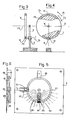
- Figs.3 and 4 show an application of the concept of this invention whereby the change from a state of rest of a mechanical member such as disk or a pulley is perceived.
- a non metallic disk O rotatable about a horizontal axis 75 is surrounded by a non metallic tube 71 within which a mass M of mercury is contained which will collect at the lower section of the tube when disk O is at rest.
- a proximity sensor S which can be supported on a stand A is located beside tube 71 at the level of the lowermost position of the mercury mass M.
- the active face FS of sensor S faces the side of tube 71 at short distance therefrom.
- this can be filled with a thick liquid L in addition to the mercury mass.
- An instrument is shown by figs.5 and 6 which serves for detecting and indicating the angular positions of an object tiltable about a horizontal axis,such as an inclinometer.
- a ring shaped non metallic tube 81 is attached by means of clamps 88 to a plate integral with said object or fastened thereto.
- a mercury mass M is contained into tube 81 and one or more proximity sensor holders 85 are mounted on tube 81 to slide along the same.
- a proximity sensor S is seated in each holder 85 and with its active face towards tube 81.
- Each sensor holder 85 is set along tube 81 at an angular position which is of interest.
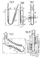
- Figs 7-10 show various cases where the concept of this invention is applied'for obtaining electrical signals corresponding to the maniscus levels of a mercury column in a manometer.
- a U-shape manometer is formed with a plastic tube 93 with two upright legs 96,98 which are fitted through a pair of holes 95,97 of a block 91 slidable along them.
- Block 91 is provided with a receptacle 92 into which a proximity sensor S is received with its active face FS slidably contacting the wall of tube 93.
- the manometer legs 96,98 are connected to respective pressure sources of which the pressure difference is to be measured. Such pressure difference, as known, will cause the mercury meniscuses to move, that is to go down in leg 96 connected to the higher pressure space and to rise in leg 98.When passing in front of the sensor active face FS, the mercury meniscus in leg 96 will cause the sensor to emit a signal signifying that the mercury meniscus is at the same level as the sensor.
- the manometer thus equipped has the advantage of affording a visual indication of the mercury level and at the same time of providing an electrical signal for actuating, for instance, a relay or similar equipment.
- one, 106,of the legs is vertical and has a larger cross section than the inclined leg 108.
- the manometer legs are supported on a vertical board T by means of brackets 195,which keep such legs distant from the table enough for inserting a proximity sensor between the manometer and the supporting board.
- the sensor will be slidable along the inclined leg 108 of the manometer by means not shown as indicated by arrows f 1 S and f S.
- the sensor active face FS will be directed toward the inclined leg of the manometer at short distance therefrom.
- Fig.10 shows a differential manometer similar to that of fig.7 - that is comprising a U-shaped tube 203 - but with a plurality of proximity sensors S 1 - S distributed along each of the manometer legs.
- the leg 208 connecting with the source of lower pressure, is equipped with sensors along the section thereof above the line Z of equal pressure of the sources with which the two legs connect,while the other leg 206 is equipped with sensors along its section below line Z. Thanks to the small size of the sensors presently available, a substantially continuous reading of the pressure difference can be obtained between the two sources with which the two legs of the manometer connect.
- the electric signals from proximity sensors S 1 - S n can be fed to an electronic apparatus 200 for conversion into analogical or digital form.
- Fig.11 shows a differential manometer usable as a flowmeter, which is equipped with proximity sensorsaccording to the invention.
- It comprises a tube 303 attached to a vertical board and coplanar therewith and consisting of two curved legs,an upper one 308 and a lower one 306 connected to one another at their lower ends.
- the tube legs are curved according to a parabola,however the parabola segment according to which the upper leg is curved is downwards convex,while the lower leg 206 is upward convex.
- the reason of such outline of tube 303 is as follows.
- the use of the above manometer is for measuring the flow of a fluid in a pipe - not shown - by measuring the drop of pressure caused by an obstruction in said pipe,the lower leg 306 of hhe manometer being connected to the pipe upstream of the obstruction and the upper leg 308 being connected to the same pipe but downstream of the obstruction, both legs sloping down from the respectiv4connections with said pipe.
- the pressure drop across the pipa obstruction is proportional to the square of the fluid velocity and then to the square of the fluid rate, so, when a manometer with vertical straight legs is used,the increase of the distance between the levels of the two mercury meniscuses corresponding to a given increment of flow rate measured along the manometer legs will not be the same at different flow rates,but will be greater at higher flow rates. However a constant increase of the meniscuses distance along the manometer legs for a given increment of the flow rate can be obtained by curving the manometer legs as above described.
- the proximity sensors are so distributed along the respective manometer legs,that the sensors of one leg are offset with respect to those of the other leg,so that, when the mercury meniscus of one leg is between two successive sensors,the maniscus of the other leg is in front of a sensor. In this way a double number of sensors can be used with respect to those which can be received along a single leg of the tube and more minute readings of the flow rate can be obtained thereby.
Landscapes
- Physics & Mathematics (AREA)
- General Physics & Mathematics (AREA)
- Electromagnetism (AREA)
- Fluid Mechanics (AREA)
- Business, Economics & Management (AREA)
- Emergency Management (AREA)
- Measuring Fluid Pressure (AREA)
- Crystals, And After-Treatments Of Crystals (AREA)
- Electron Tubes For Measurement (AREA)
- Measurement Of Length, Angles, Or The Like Using Electric Or Magnetic Means (AREA)
- Measurement Of Radiation (AREA)
- Solid-Sorbent Or Filter-Aiding Compositions (AREA)
- Electronic Switches (AREA)
- Control Of Amplification And Gain Control (AREA)
- Arrangements For Transmission Of Measured Signals (AREA)
- Switches That Are Operated By Magnetic Or Electric Fields (AREA)
- Other Investigation Or Analysis Of Materials By Electrical Means (AREA)
- Analysing Materials By The Use Of Radiation (AREA)
Priority Applications (1)
| Application Number | Priority Date | Filing Date | Title |
|---|---|---|---|
| AT83830159T ATE98768T1 (de) | 1982-07-27 | 1983-07-27 | Methode und geraet zum erhalten eines elektrischen signals in verbindung mit der position einer quecksilbermasse in instrumenten. |
Applications Claiming Priority (2)
| Application Number | Priority Date | Filing Date | Title |
|---|---|---|---|
| IT829482A IT1192486B (it) | 1982-07-27 | 1982-07-27 | Sistema per trasformare in segnali elettrici gli spostamenti di una massa di mercurio,per apparecchi di misura ed altro |
| IT948282 | 1982-07-27 |
Related Child Applications (2)
| Application Number | Title | Priority Date | Filing Date |
|---|---|---|---|
| EP93830127.2 Division-Into | 1993-04-13 | ||
| EP93830126.4 Division-Into | 1993-04-13 |
Publications (3)
| Publication Number | Publication Date |
|---|---|
| EP0104148A2 true EP0104148A2 (de) | 1984-03-28 |
| EP0104148A3 EP0104148A3 (en) | 1987-01-07 |
| EP0104148B1 EP0104148B1 (de) | 1993-12-15 |
Family
ID=11130797
Family Applications (1)
| Application Number | Title | Priority Date | Filing Date |
|---|---|---|---|
| EP83830159A Expired - Lifetime EP0104148B1 (de) | 1982-07-27 | 1983-07-27 | Gerät zum Erhalten eines elektrischen Signals in Verbindung mit der Position einer Quecksilbermasse in Instrumenten |
Country Status (11)
| Country | Link |
|---|---|
| US (2) | US4554535A (de) |
| EP (1) | EP0104148B1 (de) |
| JP (2) | JPS5999201A (de) |
| AT (1) | ATE98768T1 (de) |
| AU (1) | AU569704B2 (de) |
| CA (1) | CA1224057A (de) |
| DE (1) | DE3382725T2 (de) |
| DK (1) | DK172167B1 (de) |
| IL (1) | IL69296A (de) |
| IT (1) | IT1192486B (de) |
| ZA (1) | ZA835361B (de) |
Families Citing this family (11)
| Publication number | Priority date | Publication date | Assignee | Title |
|---|---|---|---|---|
| US4662809A (en) * | 1985-09-27 | 1987-05-05 | Fmc Corporation | Automatic level device |
| GB8819056D0 (en) * | 1988-08-11 | 1988-09-14 | Coal Industry Patents Ltd | Improved method & apparatus for steering mining machine cutter |
| DE3833062A1 (de) * | 1988-09-29 | 1990-04-05 | Schmidt Paul | Neigungswinkel-messaufnehmer |
| US5450676A (en) * | 1993-06-18 | 1995-09-19 | Thornsberry; William H. | Slope angle and level indicator apparatus |
| US5825665A (en) * | 1997-07-08 | 1998-10-20 | Swift; Daniel P. | Bicycle inclinometer |
| IT1299539B1 (it) * | 1998-07-01 | 2000-03-16 | Consiglio Nazionale Ricerche | Dispositivo per il controllo e la taratura di sensori inclinometrici ad alta precisione |
| US20040016137A1 (en) * | 2000-04-06 | 2004-01-29 | Barsky Barry E. | Electrolytic tilt sensor having a meniscus inhibitor |
| JP2003325972A (ja) | 2002-05-17 | 2003-11-18 | Nintendo Co Ltd | 傾き操作に関連して音と画像を変化させるゲーム装置およびそのゲームプログラム |
| US6983583B2 (en) * | 2003-11-21 | 2006-01-10 | Ariens Company | Lawnmower tilt sensor apparatus and method |
| US20060230837A1 (en) * | 2005-04-13 | 2006-10-19 | Wilson Robert C | Apparatus and method for use in measuring fluid flow and pressures |
| ITBG20050028A1 (it) * | 2005-05-13 | 2006-11-14 | Abb Service Srl | Dispositivo per la rilevazione della posizione di un elemento mobile ad esso accoppiato e relativo elemento mobile. |
Family Cites Families (11)
| Publication number | Priority date | Publication date | Assignee | Title |
|---|---|---|---|---|
| US3140606A (en) * | 1960-09-29 | 1964-07-14 | United Aircraft Corp | Digital rate of flow transducer |
| GB1023042A (en) * | 1962-05-07 | 1966-03-16 | Wayne Kerr Lab Ltd | Improvements in or relating to pressure responsive apparatus |
| FR1363419A (fr) * | 1963-05-03 | 1964-06-12 | Pyrometrie Ind | Dispositif suiveur à asservissement |
| US3407664A (en) * | 1966-12-27 | 1968-10-29 | Exactel Instr Co | Apparatus for manometer temperature control and temperature compensation circuit and method |
| US3839904A (en) * | 1972-09-18 | 1974-10-08 | Us Army | Magnetic fluid level detector and vibration transducer |
| SU618665A1 (ru) * | 1974-05-21 | 1978-08-05 | Институт ядерной энергетики АН Белорусской ССР | Жидкость дл манометра |
| JPS5118150A (en) * | 1974-08-03 | 1976-02-13 | Hitachi Ltd | Sentakukino chusuiko |
| JPS5334550A (en) * | 1976-09-10 | 1978-03-31 | Kobe Steel Ltd | Method of measuring oblique angle |
| US4129852A (en) * | 1977-03-25 | 1978-12-12 | Knecht J | Slope detector for indicating flat tires and the like |
| US4325190A (en) * | 1980-08-25 | 1982-04-20 | Thomas Duerst | Bow sight |
| US4414541A (en) * | 1981-05-29 | 1983-11-08 | Techne Electronics Limited | Motion sensing system |
-
1982
- 1982-07-27 IT IT829482A patent/IT1192486B/it active
-
1983
- 1983-07-20 US US06/515,526 patent/US4554535A/en not_active Expired - Fee Related
- 1983-07-21 IL IL8369296A patent/IL69296A/xx not_active IP Right Cessation
- 1983-07-22 ZA ZA835361A patent/ZA835361B/xx unknown
- 1983-07-26 CA CA000433263A patent/CA1224057A/en not_active Expired
- 1983-07-26 AU AU17293/83A patent/AU569704B2/en not_active Ceased
- 1983-07-26 DK DK342083A patent/DK172167B1/da not_active IP Right Cessation
- 1983-07-27 DE DE3382725T patent/DE3382725T2/de not_active Expired - Fee Related
- 1983-07-27 JP JP58137456A patent/JPS5999201A/ja active Pending
- 1983-07-27 AT AT83830159T patent/ATE98768T1/de not_active IP Right Cessation
- 1983-07-27 EP EP83830159A patent/EP0104148B1/de not_active Expired - Lifetime
-
1990
- 1990-07-24 US US07/555,791 patent/US5111700A/en not_active Expired - Lifetime
-
1995
- 1995-02-23 JP JP7059882A patent/JPH0989512A/ja active Pending
Non-Patent Citations (1)
| Title |
|---|
| None |
Also Published As
| Publication number | Publication date |
|---|---|
| IT8209482A0 (it) | 1982-07-27 |
| ATE98768T1 (de) | 1994-01-15 |
| IL69296A0 (en) | 1983-11-30 |
| DE3382725D1 (de) | 1994-01-27 |
| IT1192486B (it) | 1988-04-13 |
| EP0104148B1 (de) | 1993-12-15 |
| EP0104148A3 (en) | 1987-01-07 |
| DK342083A (da) | 1984-01-28 |
| DE3382725T2 (de) | 1994-06-30 |
| JPS5999201A (ja) | 1984-06-07 |
| DK172167B1 (da) | 1997-12-08 |
| IL69296A (en) | 1988-10-31 |
| US5111700A (en) | 1992-05-12 |
| CA1224057A (en) | 1987-07-14 |
| AU569704B2 (en) | 1988-02-18 |
| DK342083D0 (da) | 1983-07-26 |
| US4554535A (en) | 1985-11-19 |
| ZA835361B (en) | 1984-03-28 |
| AU1729383A (en) | 1984-02-02 |
| JPH0989512A (ja) | 1997-04-04 |
Similar Documents
| Publication | Publication Date | Title |
|---|---|---|
| EP0104148A2 (de) | Gerät zum Erhalten eines elektrischen Signals in Verbindung mit der Position einer Quecksilbermasse in Instrumenten | |
| US5136884A (en) | Magnetic sight gage sensor | |
| US4003255A (en) | Measurement and control of fluid flow | |
| US5117693A (en) | Liquid level sensor | |
| US4951506A (en) | Rolling contact ohmic resistance position sensor | |
| US5186058A (en) | Rotameter with float guides | |
| US3894433A (en) | Rotameter system with electrical read-out | |
| US4570484A (en) | Liquid measurement system | |
| US5193400A (en) | Universal rotameter | |
| US5224385A (en) | Method for obtaining electrical signals correlated with the position of a mass of mercury in instruments and the like | |
| JPS6039967B2 (ja) | 流量の測定と調整装置 | |
| KR100328741B1 (ko) | 플랜저코어를갖는액체레벨센서 | |
| JPS6037254A (ja) | 溶融金属浴の液面レベルの制御方法 | |
| US6553822B2 (en) | Liquid volume measurement | |
| EP0197100A1 (de) | Vorrichtung zur magnetischen bestimmung einer stelle | |
| JPS6036919A (ja) | 容器に収容された物質の表面レベルを測定及び制御する方法 | |
| US3688588A (en) | Apparatus for determining the density of a fluid | |
| US5337617A (en) | Gas flow meter | |
| US5022269A (en) | Resonance frequency position sensor | |
| KR0171633B1 (ko) | 유량계 | |
| SU920382A1 (ru) | Расходомер | |
| JP2793974B2 (ja) | 溶融金属のレベルを検出する方法と装置 | |
| RU185383U1 (ru) | Поплавковый уровнемер | |
| KR20020006138A (ko) | 플로트형 면적 유량계 | |
| SE512510C2 (sv) | Anordning för sann nivåmätning i en tank |
Legal Events
| Date | Code | Title | Description |
|---|---|---|---|
| PUAI | Public reference made under article 153(3) epc to a published international application that has entered the european phase |
Free format text: ORIGINAL CODE: 0009012 |
|
| AK | Designated contracting states |
Designated state(s): AT BE CH DE FR GB LI LU NL SE |
|
| 17P | Request for examination filed |
Effective date: 19840925 |
|
| PUAL | Search report despatched |
Free format text: ORIGINAL CODE: 0009013 |
|
| AK | Designated contracting states |
Kind code of ref document: A3 Designated state(s): AT BE CH DE FR GB LI LU NL SE |
|
| 17Q | First examination report despatched |
Effective date: 19890221 |
|
| GRAA | (expected) grant |
Free format text: ORIGINAL CODE: 0009210 |
|
| AK | Designated contracting states |
Kind code of ref document: B1 Designated state(s): AT BE CH DE FR GB LI LU NL SE |
|
| REF | Corresponds to: |
Ref document number: 98768 Country of ref document: AT Date of ref document: 19940115 Kind code of ref document: T |
|
| XX | Miscellaneous (additional remarks) |
Free format text: VERBUNDEN MIT 90116072.1/0414217 (EUROPAEISCHE ANMELDENUMMER/VEROEFFENTLICHUNGSNUMMER) DURCH ENTSCHEIDUNG VOM 28.10.93. |
|
| REF | Corresponds to: |
Ref document number: 3382725 Country of ref document: DE Date of ref document: 19940127 |
|
| ET | Fr: translation filed | ||
| RTI2 | Title (correction) |
Free format text: APPARATUS FOR OBTAINING ELECTRICAL SIGNALS CORRELATED WITH THE POSITION OF A MASS OF MERCURY IN INSTRUMENTS AND THE LIKE. |
|
| NLXE | Nl: other communications concerning ep-patents (part 3 heading xe) |
Free format text: ON 940526 A NEW PAGE 01 OF THE TRANSLATION OF THE PATENT SPECIFICATION HAS BEEN RECEIVED IN CONNECTION WITH A CORRECTION ISSUED BY THE E.P.O. |
|
| EPTA | Lu: last paid annual fee | ||
| PLBE | No opposition filed within time limit |
Free format text: ORIGINAL CODE: 0009261 |
|
| STAA | Information on the status of an ep patent application or granted ep patent |
Free format text: STATUS: NO OPPOSITION FILED WITHIN TIME LIMIT |
|
| 26N | No opposition filed | ||
| EAL | Se: european patent in force in sweden |
Ref document number: 83830159.6 |
|
| PGFP | Annual fee paid to national office [announced via postgrant information from national office to epo] |
Ref country code: LU Payment date: 19960701 Year of fee payment: 14 |
|
| PGFP | Annual fee paid to national office [announced via postgrant information from national office to epo] |
Ref country code: AT Payment date: 19960731 Year of fee payment: 14 |
|
| PG25 | Lapsed in a contracting state [announced via postgrant information from national office to epo] |
Ref country code: LU Free format text: LAPSE BECAUSE OF NON-PAYMENT OF DUE FEES Effective date: 19970727 Ref country code: AT Free format text: LAPSE BECAUSE OF NON-PAYMENT OF DUE FEES Effective date: 19970727 |
|
| PGFP | Annual fee paid to national office [announced via postgrant information from national office to epo] |
Ref country code: FR Payment date: 19980730 Year of fee payment: 16 Ref country code: DE Payment date: 19980730 Year of fee payment: 16 |
|
| PGFP | Annual fee paid to national office [announced via postgrant information from national office to epo] |
Ref country code: NL Payment date: 19980731 Year of fee payment: 16 |
|
| PGFP | Annual fee paid to national office [announced via postgrant information from national office to epo] |
Ref country code: CH Payment date: 19980812 Year of fee payment: 16 |
|
| PGFP | Annual fee paid to national office [announced via postgrant information from national office to epo] |
Ref country code: BE Payment date: 19980813 Year of fee payment: 16 |
|
| PGFP | Annual fee paid to national office [announced via postgrant information from national office to epo] |
Ref country code: SE Payment date: 19980817 Year of fee payment: 16 |
|
| PG25 | Lapsed in a contracting state [announced via postgrant information from national office to epo] |
Ref country code: SE Free format text: THE PATENT HAS BEEN ANNULLED BY A DECISION OF A NATIONAL AUTHORITY Effective date: 19990728 |
|
| PG25 | Lapsed in a contracting state [announced via postgrant information from national office to epo] |
Ref country code: LI Free format text: LAPSE BECAUSE OF NON-PAYMENT OF DUE FEES Effective date: 19990731 Ref country code: FR Free format text: THE PATENT HAS BEEN ANNULLED BY A DECISION OF A NATIONAL AUTHORITY Effective date: 19990731 Ref country code: CH Free format text: LAPSE BECAUSE OF NON-PAYMENT OF DUE FEES Effective date: 19990731 Ref country code: BE Free format text: LAPSE BECAUSE OF NON-PAYMENT OF DUE FEES Effective date: 19990731 |
|
| BERE | Be: lapsed |
Owner name: O'TOOLE YVONNE Effective date: 19990731 Owner name: FLORIS PIERLUIGI Effective date: 19990731 |
|
| PG25 | Lapsed in a contracting state [announced via postgrant information from national office to epo] |
Ref country code: NL Free format text: LAPSE BECAUSE OF NON-PAYMENT OF DUE FEES Effective date: 20000201 |
|
| REG | Reference to a national code |
Ref country code: CH Ref legal event code: PL |
|
| EUG | Se: european patent has lapsed |
Ref document number: 83830159.6 |
|
| NLV4 | Nl: lapsed or anulled due to non-payment of the annual fee |
Effective date: 20000201 |
|
| PG25 | Lapsed in a contracting state [announced via postgrant information from national office to epo] |
Ref country code: DE Free format text: LAPSE BECAUSE OF NON-PAYMENT OF DUE FEES Effective date: 20000503 |
|
| REG | Reference to a national code |
Ref country code: FR Ref legal event code: ST |
|
| REG | Reference to a national code |
Ref country code: GB Ref legal event code: IF02 |
|
| PGFP | Annual fee paid to national office [announced via postgrant information from national office to epo] |
Ref country code: GB Payment date: 20020719 Year of fee payment: 20 |
|
| PG25 | Lapsed in a contracting state [announced via postgrant information from national office to epo] |
Ref country code: GB Free format text: LAPSE BECAUSE OF EXPIRATION OF PROTECTION Effective date: 20030726 |
|
| REG | Reference to a national code |
Ref country code: GB Ref legal event code: PE20 |
|
| APAH | Appeal reference modified |
Free format text: ORIGINAL CODE: EPIDOSCREFNO |