EP0104155A1 - Dispositif tendeur pour sangle - Google Patents
Dispositif tendeur pour sangle Download PDFInfo
- Publication number
- EP0104155A1 EP0104155A1 EP83850236A EP83850236A EP0104155A1 EP 0104155 A1 EP0104155 A1 EP 0104155A1 EP 83850236 A EP83850236 A EP 83850236A EP 83850236 A EP83850236 A EP 83850236A EP 0104155 A1 EP0104155 A1 EP 0104155A1
- Authority
- EP
- European Patent Office
- Prior art keywords
- strap
- roller
- tensioning
- rollers
- tensioning device
- Prior art date
- Legal status (The legal status is an assumption and is not a legal conclusion. Google has not performed a legal analysis and makes no representation as to the accuracy of the status listed.)
- Withdrawn
Links
- 230000000903 blocking effect Effects 0.000 abstract 1
- 238000004804 winding Methods 0.000 abstract 1
- 239000000969 carrier Substances 0.000 description 4
- 239000013536 elastomeric material Substances 0.000 description 3
- 239000002184 metal Substances 0.000 description 3
- 239000012779 reinforcing material Substances 0.000 description 3
- 239000004566 building material Substances 0.000 description 1
- 230000014759 maintenance of location Effects 0.000 description 1
- 238000004519 manufacturing process Methods 0.000 description 1
- 238000000465 moulding Methods 0.000 description 1
- 230000002787 reinforcement Effects 0.000 description 1
- 230000003014 reinforcing effect Effects 0.000 description 1
- 230000000717 retained effect Effects 0.000 description 1
Images

Classifications
-
- B—PERFORMING OPERATIONS; TRANSPORTING
- B60—VEHICLES IN GENERAL
- B60P—VEHICLES ADAPTED FOR LOAD TRANSPORTATION OR TO TRANSPORT, TO CARRY, OR TO COMPRISE SPECIAL LOADS OR OBJECTS
- B60P7/00—Securing or covering of load on vehicles
- B60P7/06—Securing of load
- B60P7/08—Securing to the vehicle floor or sides
- B60P7/0823—Straps; Tighteners
- B60P7/083—Tensioning by repetetive movement of an actuating member
Definitions
- This invention relates to a strap tensioning device of the kind comprising a rotatably mounted strap roller about which the strap is intended to run.
- Load carriers of the type adapted to be clamped to the drip mouldings of vehicle roofs with a view to carrying different kinds of bulky objects thereon have found an ever increasing employment.
- the load carriers may be for instance luggage carriers, ski racks, surfboard racks, canoe racks, etc.
- each of the wires of reinforcing material consists of a plurality of twisted-together metal wires.
- the described design of the strap gives rise to difficulties when the strap is tensioned for securing objects to the load carrier since the strap because of the reinforcing material embedded therein is not so flexible as to permit being conventionally wound onto a conventional type strap roller.
- the present invention therefore has for its purpose to provide a strap tensioning device which is suited for use in tensioning a strap which is relatively stiff because it is provided with a reinforcement.
- the strap tensioning device comprises, in addition to a rotatably mounted strap roller about which the strap is adapted to run over at least part of the periphery of the roller, a second rotatably mounted clamping roller against which the strap roller is arranged to be urged in order to clamp the strap between the rollers, and at least one of the rollers is adapted to be blocked against rotation for fixation of the strap.
- the strap roller is mounted so as to be movable towards and away from the clamping roller in a direction making an' angle with a plane extending through the axes of rotation of the rollers, and so that a pull at the strap brings about said urging of the strap roller against the clamping roller.
- a tensioning arm' is associated with one of the rollers to rotate that roller for tensioning of the strap
- a latching device is associated with one of the rollers for fixation of that roller in the tensioned position of the strap, said latching device being releaseable by means of the tensioning arm.
- the two rollers are suitably interconnected by means of gear or tooth wheels.
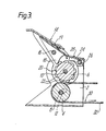
- a strap tensioning device comprises a housing 2 in which a strap roller 4 and a clamping roller 6 are rotatably mounted, each on an axis of rotation 8 and 10, respectively.
- the axis 8 is mounted in slots 12 in the housing 12 so that the strap roller 4 is movable in a direction making an angle of about 60 0 with a plane extending through the axes 8 and 10.
- the strap roller 4 is thus movable obliquely towards and away from the clamping roller 6.
- a tensioning arm 14 is arranged on the same axis 10 as the clamping roller 6 and can thus pivot about said axis 10.
- the tensioning arm 14 has a pawl 18 which is rockably mounted on a pin 16 and loaded with a spring 20.
- the pawl 18 is adapted to engage d tooth wheel 20 which is fixedly connected with the clamping roller 6 and the teeth 22 of which are adapted also to engage a pawl 24 which is mounted on a pin 26 and loaded with a spring 28.
- rollers 4 and 6 are associated with each other by means of the tooth wheels 34 and 36, respectively, which are fixedly connected with the respective roller and thereby cause the rollers to rotate simultaneously in opposite directions.
- a strap 30 which preferably is of the kind described in SE-Patent No. 8204961-0, i.e. it consists of an elastomeric material with reinforcing wires of metal embedded therein.
- the part of the strap designated by reference numeral 32 is meant to extend upwards over a load which is to be secured by means of the strap and the strap tensioning device.
- the strap tensioning device is intended for fixation to a load carrier for vehicles in order to be used in tensioning the strap 30 when the latter is utilized for retaining various objects, such as surf- boards, canoes, building material etc., to the load carrier.
- the strap roller 4 takes the position illustrated in Fig. 3, in which the axis 8 is at the lower left ends of the slots 12 and the strap roller 4 is thus spaced from the clamping roller 6. In this position the end of a strap can be passed about the strap roller 4 and in between the strap roller 4 and the clamping roller 6 to the position illustrated in Fig. 3.
- the tensioning arm 14 can be employed to provide a continued tensioning of the strap 30 by rotation of the clamping roller 6.
- the tensioning arm 14 is rotated counter-clockwise from the position illustrated in Fig. 3 the pawl 18 will engage the teeth 22 to rotate the clamping roller 6 counter-clockwise. During this counter-clockwise rotation the pawl 24 will snap over the teeth 22.
- the tensioning action can be continued by clockwise rotation of the tensioning arm, the pawl 18 of the tensioning arm 14 snapping over the teeth 22 of the tooth wheel 20; at this movement of the tensioning arm 14 the tooth wheel 20 and thereby the clamping roller 6 are kept 'latched by the pawl 24.
- tensioning of the clamping roller 6 may be continued in that the tensioning arm 14 is again swung counter-clockwise in the described manner.
- the tensioning arm 14 For release of the strap 30 the tensioning arm 14 is moved to the position illustrated in Fig. 3, in which the pawl 24 is raised out of engagement with the teeth 22 of the tooth wheel 20. In this position the rollers 4 and 6 can thus rotate in a direction for releasing the strap 30.
- the strap tensioning device according to the invention when used in connection with a load carrier, can be connected with said carrier in such a way that a locking device associated with the load carrier can be utilized to lock the tensioning arm 14 in the position shown in Figs. 1 and 2. As a result, the strap will be blocked in the tensioned state.
Landscapes
- Engineering & Computer Science (AREA)
- Transportation (AREA)
- Mechanical Engineering (AREA)
- Fittings On The Vehicle Exterior For Carrying Loads, And Devices For Holding Or Mounting Articles (AREA)
- Emergency Lowering Means (AREA)
Applications Claiming Priority (2)
| Application Number | Priority Date | Filing Date | Title |
|---|---|---|---|
| SE8205121 | 1982-09-09 | ||
| SE8205121A SE8205121L (sv) | 1982-09-09 | 1982-09-09 | Bandspennare |
Publications (1)
| Publication Number | Publication Date |
|---|---|
| EP0104155A1 true EP0104155A1 (fr) | 1984-03-28 |
Family
ID=20347768
Family Applications (1)
| Application Number | Title | Priority Date | Filing Date |
|---|---|---|---|
| EP83850236A Withdrawn EP0104155A1 (fr) | 1982-09-09 | 1983-09-05 | Dispositif tendeur pour sangle |
Country Status (3)
| Country | Link |
|---|---|
| EP (1) | EP0104155A1 (fr) |
| JP (1) | JPS5967136A (fr) |
| SE (1) | SE8205121L (fr) |
Cited By (7)
| Publication number | Priority date | Publication date | Assignee | Title |
|---|---|---|---|---|
| WO1987007691A1 (fr) * | 1986-06-07 | 1987-12-17 | Burkhard Kreiss | Appareil de traction de cable |
| WO1996029274A1 (fr) * | 1995-03-22 | 1996-09-26 | Henry Norrby | Outil pour appliquer une force servant a tendre une bande |
| EP1223078A1 (fr) * | 2001-01-15 | 2002-07-17 | Thiriet Fils Société Anonyme | Dispositif d'enroulement à commande manuelle d'un élément enroulable |
| USD661562S1 (en) | 2010-06-18 | 2012-06-12 | Master Lock Company Llc | Ratchet |
| WO2012168687A1 (fr) * | 2011-06-06 | 2012-12-13 | C.P.Witter Limited | Porteur de charge destiné à un véhicule |
| USD681411S1 (en) | 2011-08-30 | 2013-05-07 | Master Lock Company Llc | Ratchet lock |
| FR3034057A1 (fr) * | 2015-03-24 | 2016-09-30 | Thiriet | Dispositif d'enroulement a commande manuelle d'un element enroulable |
Citations (3)
| Publication number | Priority date | Publication date | Assignee | Title |
|---|---|---|---|---|
| GB2016625A (en) * | 1977-10-19 | 1979-09-26 | Taylor D H | Devices for tensioning flexible elements |
| DE2914888A1 (de) * | 1979-04-12 | 1980-10-23 | Sicherheits Und Bankeinrichtun | Gurtratsche zum spannen eines gurtes |
| WO1982001351A1 (fr) * | 1980-10-10 | 1982-04-29 | Lennart Lindblad | Treuil a courroie |
-
1982
- 1982-09-09 SE SE8205121A patent/SE8205121L/ not_active Application Discontinuation
-
1983
- 1983-09-05 EP EP83850236A patent/EP0104155A1/fr not_active Withdrawn
- 1983-09-09 JP JP16536083A patent/JPS5967136A/ja active Pending
Patent Citations (3)
| Publication number | Priority date | Publication date | Assignee | Title |
|---|---|---|---|---|
| GB2016625A (en) * | 1977-10-19 | 1979-09-26 | Taylor D H | Devices for tensioning flexible elements |
| DE2914888A1 (de) * | 1979-04-12 | 1980-10-23 | Sicherheits Und Bankeinrichtun | Gurtratsche zum spannen eines gurtes |
| WO1982001351A1 (fr) * | 1980-10-10 | 1982-04-29 | Lennart Lindblad | Treuil a courroie |
Cited By (14)
| Publication number | Priority date | Publication date | Assignee | Title |
|---|---|---|---|---|
| WO1987007691A1 (fr) * | 1986-06-07 | 1987-12-17 | Burkhard Kreiss | Appareil de traction de cable |
| EP0252313A1 (fr) * | 1986-06-07 | 1988-01-13 | Burkhard Prof. Kreiss | Dispositif de traction pour câbles |
| WO1996029274A1 (fr) * | 1995-03-22 | 1996-09-26 | Henry Norrby | Outil pour appliquer une force servant a tendre une bande |
| US5904341A (en) * | 1995-03-22 | 1999-05-18 | Norrby; Henry | Device for the application of a tensioning force in a strap |
| EP1223078A1 (fr) * | 2001-01-15 | 2002-07-17 | Thiriet Fils Société Anonyme | Dispositif d'enroulement à commande manuelle d'un élément enroulable |
| FR2819501A1 (fr) * | 2001-01-15 | 2002-07-19 | Thiriet Fils | Dispositif d'enroulement a commande manuelle d'un element enroulable |
| USD661562S1 (en) | 2010-06-18 | 2012-06-12 | Master Lock Company Llc | Ratchet |
| USD675498S1 (en) | 2010-06-18 | 2013-02-05 | Master Lock Company Llc | Ratchet |
| WO2012168687A1 (fr) * | 2011-06-06 | 2012-12-13 | C.P.Witter Limited | Porteur de charge destiné à un véhicule |
| US10035469B2 (en) | 2011-06-06 | 2018-07-31 | Horizon Global Americas Inc. | Carrier for a vehicle |
| USD681411S1 (en) | 2011-08-30 | 2013-05-07 | Master Lock Company Llc | Ratchet lock |
| USD729026S1 (en) | 2011-08-30 | 2015-05-12 | Master Lock Company Llc | Ratchet lock |
| FR3034057A1 (fr) * | 2015-03-24 | 2016-09-30 | Thiriet | Dispositif d'enroulement a commande manuelle d'un element enroulable |
| EP3078521A1 (fr) * | 2015-03-24 | 2016-10-12 | Thiriet | Dispositif d'enroulement a commande manuelle d'un element enroulable |
Also Published As
| Publication number | Publication date |
|---|---|
| JPS5967136A (ja) | 1984-04-16 |
| SE8205121D0 (sv) | 1982-09-09 |
| SE8205121L (sv) | 1984-03-10 |
Similar Documents
| Publication | Publication Date | Title |
|---|---|---|
| US10279747B2 (en) | Attachment devices for vehicle rooftop rack accessories | |
| US5282706A (en) | Retractable tie-down assembly | |
| US5058244A (en) | Free falling cinch tongue | |
| US5816185A (en) | Ratcheting means for quickly securing a cover over a boat and the method of using the same | |
| US5052605A (en) | Attachment arrangement for a cycle | |
| US7111764B2 (en) | Clamp assembly for securing a ladder to a vehicle rack | |
| GB1582410A (en) | Package strand tensioner | |
| US6321961B1 (en) | Bicycle retention bracket | |
| GB2082279A (en) | Strap tightener | |
| US3550875A (en) | Restraint apparatus | |
| US4249708A (en) | Emergency locking mechanism for the seat belt retractor of vehicles | |
| EP0104155A1 (fr) | Dispositif tendeur pour sangle | |
| US5000481A (en) | Locking device for vehicle seat belts | |
| US5316266A (en) | Strap extender and tensioning system | |
| US4398680A (en) | Webbing locking device | |
| US20030059269A1 (en) | Cargo restraint apparatus | |
| US3323831A (en) | Retractable seat belt construction | |
| US4878272A (en) | Tongue assembly | |
| US6092869A (en) | Apparatus to improve the retention of a child seat in a vehicle | |
| US20060188354A1 (en) | Cargo restraint apparatus | |
| US6327752B1 (en) | Clamping device for securing a cable | |
| US5192035A (en) | Retractor with manual cinch | |
| US6530127B2 (en) | Restraint device with release mechanism | |
| US6076805A (en) | Rope pulling device | |
| JPS62116338A (ja) | ベルトの締付け手段 |
Legal Events
| Date | Code | Title | Description |
|---|---|---|---|
| PUAI | Public reference made under article 153(3) epc to a published international application that has entered the european phase |
Free format text: ORIGINAL CODE: 0009012 |
|
| AK | Designated contracting states |
Designated state(s): AT BE CH DE FR GB IT LI NL |
|
| 17P | Request for examination filed |
Effective date: 19841001 |
|
| STAA | Information on the status of an ep patent application or granted ep patent |
Free format text: STATUS: THE APPLICATION IS DEEMED TO BE WITHDRAWN |
|
| 18D | Application deemed to be withdrawn |
Effective date: 19850402 |
|
| RIN1 | Information on inventor provided before grant (corrected) |
Inventor name: THULIN, WILLIS |