EP0104216B1 - Elastische radnabe für speichenräder für fahrrad - Google Patents
Elastische radnabe für speichenräder für fahrrad Download PDFInfo
- Publication number
- EP0104216B1 EP0104216B1 EP19830901080 EP83901080A EP0104216B1 EP 0104216 B1 EP0104216 B1 EP 0104216B1 EP 19830901080 EP19830901080 EP 19830901080 EP 83901080 A EP83901080 A EP 83901080A EP 0104216 B1 EP0104216 B1 EP 0104216B1
- Authority
- EP
- European Patent Office
- Prior art keywords
- hub
- flanges
- sleeve
- hub according
- wheel
- Prior art date
- Legal status (The legal status is an assumption and is not a legal conclusion. Google has not performed a legal analysis and makes no representation as to the accuracy of the status listed.)
- Expired
Links
- 239000000463 material Substances 0.000 claims description 14
- 239000004033 plastic Substances 0.000 claims description 8
- 239000004952 Polyamide Substances 0.000 claims description 6
- 229920002647 polyamide Polymers 0.000 claims description 6
- 230000000295 complement effect Effects 0.000 claims description 5
- 239000011521 glass Substances 0.000 claims description 5
- 229920002302 Nylon 6,6 Polymers 0.000 claims description 4
- 239000003365 glass fiber Substances 0.000 claims description 4
- 230000002093 peripheral effect Effects 0.000 claims description 2
- 239000002184 metal Substances 0.000 description 10
- 238000004519 manufacturing process Methods 0.000 description 9
- 238000000465 moulding Methods 0.000 description 6
- 238000000034 method Methods 0.000 description 5
- 239000011324 bead Substances 0.000 description 4
- 230000000694 effects Effects 0.000 description 4
- 238000005260 corrosion Methods 0.000 description 2
- 230000007797 corrosion Effects 0.000 description 2
- 238000006073 displacement reaction Methods 0.000 description 2
- 238000009826 distribution Methods 0.000 description 2
- 239000013013 elastic material Substances 0.000 description 2
- 230000014759 maintenance of location Effects 0.000 description 2
- KXGFMDJXCMQABM-UHFFFAOYSA-N 2-methoxy-6-methylphenol Chemical compound [CH]OC1=CC=CC([CH])=C1O KXGFMDJXCMQABM-UHFFFAOYSA-N 0.000 description 1
- 229920000297 Rayon Polymers 0.000 description 1
- 230000015572 biosynthetic process Effects 0.000 description 1
- 230000005489 elastic deformation Effects 0.000 description 1
- 229920001971 elastomer Polymers 0.000 description 1
- 239000000835 fiber Substances 0.000 description 1
- 239000000945 filler Substances 0.000 description 1
- 238000005461 lubrication Methods 0.000 description 1
- 229920001568 phenolic resin Polymers 0.000 description 1
- 239000005011 phenolic resin Substances 0.000 description 1
- 239000002964 rayon Substances 0.000 description 1
- 230000002787 reinforcement Effects 0.000 description 1
- 239000005060 rubber Substances 0.000 description 1
- 238000007789 sealing Methods 0.000 description 1
- 239000007787 solid Substances 0.000 description 1
- 229920003002 synthetic resin Polymers 0.000 description 1
- 239000000057 synthetic resin Substances 0.000 description 1
- 238000009864 tensile test Methods 0.000 description 1
- 229920005992 thermoplastic resin Polymers 0.000 description 1
- 238000003466 welding Methods 0.000 description 1
Images


Classifications
-
- B—PERFORMING OPERATIONS; TRANSPORTING
- B60—VEHICLES IN GENERAL
- B60B—VEHICLE WHEELS; CASTORS; AXLES FOR WHEELS OR CASTORS; INCREASING WHEEL ADHESION
- B60B5/00—Wheels, spokes, disc bodies, rims, hubs, wholly or predominantly made of non-metallic material
- B60B5/02—Wheels, spokes, disc bodies, rims, hubs, wholly or predominantly made of non-metallic material made of synthetic material
-
- B—PERFORMING OPERATIONS; TRANSPORTING
- B60—VEHICLES IN GENERAL
- B60B—VEHICLE WHEELS; CASTORS; AXLES FOR WHEELS OR CASTORS; INCREASING WHEEL ADHESION
- B60B27/00—Hubs
- B60B27/02—Hubs adapted to be rotatably arranged on axle
- B60B27/023—Hubs adapted to be rotatably arranged on axle specially adapted for bicycles
-
- B—PERFORMING OPERATIONS; TRANSPORTING
- B60—VEHICLES IN GENERAL
- B60B—VEHICLE WHEELS; CASTORS; AXLES FOR WHEELS OR CASTORS; INCREASING WHEEL ADHESION
- B60B9/00—Wheels of high resiliency, e.g. with conical interacting pressure-surfaces
- B60B9/02—Wheels of high resiliency, e.g. with conical interacting pressure-surfaces using springs resiliently mounted bicycle rims
- B60B9/10—Wheels of high resiliency, e.g. with conical interacting pressure-surfaces using springs resiliently mounted bicycle rims of rubber or the like
- B60B9/12—Wheels of high resiliency, e.g. with conical interacting pressure-surfaces using springs resiliently mounted bicycle rims of rubber or the like in the form of sleeves or rings concentric with the wheel axis
Definitions
- the present invention relates to bicycle spoke wheel hubs.
- Such hubs generally have a cylindrical central axis or hub body, limited at its two ends by two substantially perpendicular flanges.
- Each of the flanges comprises a ring of holes for receiving the ends of the spokes connecting the hub to the rim of the wheel and is made of an elastically deformable material.
- the spokes include a straight rod, one end of which is curved substantially at a right angle to end in a head. In the crown of holes, the spokes are introduced by their rod alternately on one side and the other of the flange, the heads coming to block at the entrance of the holes.
- the hubs used to date are made of metal or of materials with high mechanical resistance so as to withstand the tensile forces exerted by the spokes. Hitherto, attempts have been made to produce very solid and rigid hubs, in order to avoid any subsequent deformation of the wheel.
- Patent G B-A-13,712 describes a hub produced by assembling two stamped metal parts each comprising a flange.
- Certain embodiments combine parts made of metal and parts made of another material such as plastic or rubber.
- metal flanges are integral with an outer cylinder (17) surrounding a sleeve of elastic material (18) ensuring an elastic connection with an inner cylinder (14) carrying the axis (12 ). It is therefore a rigid hub (17) resiliently mounted on its axis.
- Patent DE-A-2 927 138 describes a hub in which two metal flanges (12) are fitted at the end of a central part (10) of plastic material carrying the bearings.
- metal parts (5a, 6a, 7a) forming the core of the hub are overmolded in a phenolic resin preventing corrosion.
- the hub body (10), comprising the flanges (50), is entirely made of a "Valex 420" thermoplastic resin chosen for its lightness, non-corrosion, self-lubrication and its rigidity.
- the object of the present invention is in particular to provide a spoke wheel hub which makes it possible to considerably facilitate the adjustment and balancing of the wheel, in particular by reducing the influence of the friction of the spokes at the crossing point, and by ensuring optimum distribution. mechanical stresses between the spokes. This also prevents spoke breaks, the load being evenly distributed among several spokes.
- Another object of the present invention is to provide a wheel hub allowing the production of spoked wheels have elasticity characteristics which, although limited, considerably increase the comfort of the user.
- Another object of the invention is to provide such a hub, the production of which is particularly inexpensive since it is obtained by molding; the molds used are particularly simple, and have jaws with a single movement so that the same mold can produce several parts at the same time.
- Another object of the invention is to provide a set of parts as small as possible and the assembly of which allows the hubs of the front and rear wheels to be produced.
- Another object of the invention is to provide such a hub made of elastic material mounted on a metal axis and in which the effects of differential expansions between the axis and the hub are compensated.
- the flexibility of the elastically deformable material from which each flange of the hub is produced is such that an axial traction of approximately 300 Newton is exerted on a single ray produces a displacement of the head of the ray, with respect to the axis of the means, of between one and four tenths of a millimeter.
- This flexibility is 20 to 100 times greater than that presented by the known devices mentioned above.
- This elasticity ensures the balancing of the mechanical forces and their distribution between all the spokes, on the one hand during assembly, and on the other hand during the subsequent use of the wheel.
- the flanges are produced from a polyamide of the Nylon 6-6 type comprising a load of 25 to 35% of glass fiber and 15 to 25% of glass beads manufactured by the company LNP.
- the hub comprises first and second plastic parts each comprising one of the two flanges provided with holes; the parts include parts of complementary profiles which fit into one another, with friction, in the direction of the axis and preventing any rotation of one relative to the other.
- the hub is thus produced in several pieces so that the molding is facilitated, and carried out using simple molds.
- the usual molding techniques would of course allow the production of a hub in one piece, but would require the use of a mold with side jaws associated with retractable pins for the formation of crowns of holes; the holes being offset on one flange relative to the other flange, the parting line of the mold should pass a quarter of the distance of two holes, which leaves very little room for the pins and leads to molds very complex.
- such a technique would not allow the special shape of the holes to be produced in a simple manner which will be described below.
- the complementary profiles of the two parts forming the hub are asymmetrical so as to allow the two parts to fit together only in a limited number of angular positions. This facilitates mounting regardless of the number of holes in the hub ring, automatically ensuring the offset of the holes from one flange to another.
- the first part is produced by assembling a sleeve and a first half of the hub body supporting the flange, the sleeve projecting from the body of the hub to receive the second part by fitting. This minimizes the number of parts needed to make the front and rear hubs.
- the sleeve is an inner sleeve and has an axial central bore and an outer surface shaped to receive the half body of the hub supporting the flanges.
- the front and rear hubs can thus be produced by adapting a different sleeve, the rear sleeve having to comprise at one of its ends a threaded part intended to receive the freewheel.
- the sleeve comprises peripheral longitudinal ribs of substantially semi-circular section, engaging in corresponding longitudinal grooves formed in the central bore of the first and of the second part.
- a hub is thus produced in which the two parts supporting the flanges are angularly held very firmly and can withstand significant torsional stresses, this embodiment also making it possible to avoid shrinkage during the production of the molded parts.
- the sleeve has an internal bore shaped to receive two needle bearings force-fitted and receiving the axis; thrust ball bearings are pressed on either side against the hub by nuts screwed onto the threaded end of the axle, elastic means being interposed between the thrust bearings and the hub body, and a sealing gasket covering stop.
- the force fitting of the needle bearings makes it possible to avoid the appearance of play during an increase in temperature, under the effect of differential expansions of the hub and of the metal parts; on the other hand the elastic means interposed between the stops and the hub body provide centering and elastic retention of the hub on the axis, while allowing differential expansion without stress between the hub and the stops.
- the faces of the flanges are conical at an angle such that the spokes leave tangentially to the conical surface. This eliminates the friction of the spoke against the flanges to allow the free play of the elasticity of the hub.
- the holes have two conical bores opposite by their apex and emerging through their base perpendicular to each of the faces of the flange; the angle of the cones is chosen so that the generatrices closest to the axis of the hub are parallel to this axis.
- the cones are connected to the flanges by a rounded toric surface, the section of which has a radius of curvature less than the radius of curvature inside the bend of the radius rod.
- the elbow of the spoke rod thus comes to rest against the toric surface and, under the effect of a pull on this rod, locally crushes the toric surface whose elasticity is added to the effects of the elasticity of the flange itself. even.
- the spoke wheel hub comprises plastic parts, and in particular the flanges of the hub.
- a plastic material will preferably be used, the flexibility of which is clearly greater than that of a metal, so that the flanges have elasticity characteristics allowing a slight deformation under the action of a traction effected on the spokes.
- provision may be made of polyamide hubs of the Nylon 6-6 type, comprising a load of 25 to 35% of glass fiber and 15 to 25% of glass beads, sold by the company LNP. A load of 30% glass fibers and 20% glass beads may be preferred.
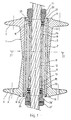
- the hub generally comprises a substantially cylindrical central axis or hub body 1, limited at its two ends by two perpendicular flanges 2 and 3.
- the flanges 2 and 3 have a ring of holes 4 for inserting spokes.
- the hub is obtained by assembling three main parts: a first half hub body 5 secured to the flange 2 and a second half hub body 6 secured to the flange 3, the two half bodies 5 and 6 being fitted onto a longitudinal sleeve 7.
- the half bodies 5 and 6 are identical and mounted in opposition, as shown in the figures; they have an internal bore 8 provided with longitudinal grooves 9 in which are housed ribs 10 of corresponding profile of the sleeve 7.
- the holes 4 formed on the flange 2 are offset with respect to the holes formed on the flange 3, so that the angular position of the half bodies 5 and 6 must be determined during assembly.
- the sleeve 7 and the corresponding bore 8 are given a complementary and asymmetrical shape so that the mounting can only be done in one angular position.
- This asymmetrical shape can for example be obtained, as shown in FIG. 3, by providing a continuous series of grooves 9 and ribs 10 regularly distributed, a rib 10 and a corresponding groove 9 being omitted.
- the ribs 10 and grooves 9 have a semi-circular section, this arrangement making it possible to avoid the occurrence of shrinkage during molding.
- the sleeve 7 has a longitudinal central bore 11 intended to receive the axis 12 of the hub.
- the hub is centered on the axis 12 by means of needle bearings 13 and 14 inserted in housings 15 and 16 of the bore 11 provided for this purpose.
- the housings 15 and 16 have a dimension such that the needle bearings are force fitted into the housings so that, when the temperature rises, the expansion of the sleeve 7 does not cause it to detach from the bearings 14 and 13.
- the hub is held axially by two ball bearings 16 and 17 inserted in a housing respectively 18 and 19 of the sleeve 7 as shown in the figures; a set of nuts 20 and locknuts 21 screwed onto the axis 12 pushes the stops 17 and 16 towards the center of the hub, elastic shims 22 and 23 being interposed between the stops 17 and 16 and the housing bottom 19 and 18 corresponding to ensure elastic retention in a centered position of the hub on the axis. Seals 24 and 25 seal the assembly and come to bear on an outer cylindrical portion 26 and 27 of the nuts 20 and 20 '.
- Figure 1 there is shown a hub for the front wheel of a bicycle, in which the two ends of the hub are identical.
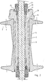
- FIG. 2 a hub for the rear wheel of a bicycle has been shown: in this case the sleeve 7 has at one of its ends a threaded head 28, protruding outside the hub body, and intended to receive the freewheel.
- the other parts of the device are the same as those of the front wheel hub.
- the rear wheel and front wheel hubs are produced with three main types of parts: a half of the hub body with a flange, a sleeve for the front wheel and a sleeve with head 28 for the rear wheel.
- Figure 4 shows the shape detail of the holes and flanges in this embodiment.
- the flange 2 Relative to the axial direction of the hub, represented by the line 29, the flange 2 is limited by two conical faces 30 and 31.
- the inner face 30, disposed on the side of the center of the hub, has its cone top directed towards the center of the hub and, for a bicycle wheel of about seventy centimeters of adimeter, a cone angle of one hundred and seventy-two degrees.
- the rod of radius 32 leaving the hole 4 which makes an angle substantially equal to eighty-six degrees with the axial direction 29, is substantially parallel to the face 30.
- the outer face 31 of the flange, or face turned towards the outside of the hub, is also conical, the top of the cone being turned towards the outside of the hub.
- the angle at the top of the cone of the outer face 31 will be close to one hundred and fifty six degrees; in fact, the radius rod emerging from the hole through the face 31 usually makes an angle of seventy-eight degrees with the axial direction 29, so that this rod is parallel to the face 31.
- the hole 4 has two opposite flared parts, a part 33 opening onto the internal face 30 and a part 34 opening onto the external face 31.
- frustoconical parts 33 and 34 may be provided, as shown in FIG. figure, the part 33 admitting an axis 35 of symmetry perpendicular to the face 30, the part 34 admitting an axis of symmetry 36 perpendicular to the face 31.
- the opening angles of the cones of the parts 33 and 34 are chosen so that the generating lines, respectively 37 and 38, those closest to the axis 29 of the hub are parallel to this axis to facilitate demolding of the part.
- the frustoconical parts 33 and 34 are connected to the faces 30 and 31 by a rounded surface.
- the half body of the hub with flange will preferably be produced in a mold whose joint plane passes through the edge 44 of the flanges, the two jaws of the mold opening and closing in the axial direction of line 29.
- the above embodiment is intended for a bicycle wheel of about seventy centimeters in diameter, and whose crowns of holes have eighteen holes.
- the angles and relative arrangements described must of course be adapted when making holes of different diameter or having a different number of radii.
- the hub comprises two types of elements ensuring elastic support of the spokes by recalling them inwards against a traction exerted on their rod towards the outside: a first means is the material constituting the flange itself, elastic plastic which allows deformation of the flange and a distance of the hole 4 under the action of a traction exerted on the spoke; a second means is the difference in curvature between the toric surfaces 39 and 40 and the elbow 43 of the radius: the elbow 43 of radius is supported on only a portion of the toric surface 39 or 40, so that a traction on the rod 32 of radius produces localized crushing of the toric surface 39, crushing ensuring relative flexibility.
- the radius 41 is substantially equal to three quarters of the inside radius of curvature of the elbow 43.
- the present invention is not limited to the embodiments which have been explicitly described, but it includes the various variants and generalizations thereof contained in the field of claims below.
Landscapes
- Engineering & Computer Science (AREA)
- Mechanical Engineering (AREA)
- Chemical & Material Sciences (AREA)
- Materials Engineering (AREA)
- Injection Moulding Of Plastics Or The Like (AREA)
- Rolling Contact Bearings (AREA)
- Pulleys (AREA)
Claims (11)
Priority Applications (1)
| Application Number | Priority Date | Filing Date | Title |
|---|---|---|---|
| AT83901080T ATE24688T1 (de) | 1982-04-01 | 1983-03-31 | Elastische radnabe fuer speichenraeder fuer fahrrad. |
Applications Claiming Priority (2)
| Application Number | Priority Date | Filing Date | Title |
|---|---|---|---|
| FR8205994 | 1982-04-01 | ||
| FR8205994A FR2524395B1 (fr) | 1982-04-01 | 1982-04-01 | Moyeu elastique pour roue a rayons |
Publications (2)
| Publication Number | Publication Date |
|---|---|
| EP0104216A1 EP0104216A1 (de) | 1984-04-04 |
| EP0104216B1 true EP0104216B1 (de) | 1987-01-07 |
Family
ID=9272813
Family Applications (1)
| Application Number | Title | Priority Date | Filing Date |
|---|---|---|---|
| EP19830901080 Expired EP0104216B1 (de) | 1982-04-01 | 1983-03-31 | Elastische radnabe für speichenräder für fahrrad |
Country Status (5)
| Country | Link |
|---|---|
| EP (1) | EP0104216B1 (de) |
| JP (1) | JPS59500510A (de) |
| DE (1) | DE3368893D1 (de) |
| FR (1) | FR2524395B1 (de) |
| WO (1) | WO1983003389A1 (de) |
Cited By (1)
| Publication number | Priority date | Publication date | Assignee | Title |
|---|---|---|---|---|
| DE9109039U1 (de) * | 1991-07-13 | 1991-10-31 | Lothar Laflör GmbH & Co, 5620 Velbert | Speichenradnabe, insbesondere für Rollstühle |
Families Citing this family (6)
| Publication number | Priority date | Publication date | Assignee | Title |
|---|---|---|---|---|
| US5372407A (en) * | 1993-07-29 | 1994-12-13 | Harley-Davidson, Inc. | Laced wheel hub |
| US6296322B1 (en) * | 1998-11-10 | 2001-10-02 | Marzocchi, S.P.A. | Quick release dropout and wheel hub assembly |
| IT1320644B1 (it) | 2000-09-15 | 2003-12-10 | Campagnolo Srl | Mozzo ruota per bicicletta. |
| IT1321025B1 (it) * | 2000-10-12 | 2003-12-30 | Campagnolo Srl | Mozzo ruota di bicicletta. |
| WO2011129027A1 (ja) * | 2010-04-12 | 2011-10-20 | 有限会社御器所技研 | 自転車用ハブ装置 |
| JP5745436B2 (ja) * | 2012-02-03 | 2015-07-08 | 株式会社 近藤機械製作所 | 自転車用ハブ装置 |
Family Cites Families (7)
| Publication number | Priority date | Publication date | Assignee | Title |
|---|---|---|---|---|
| GB191213712A (en) * | 1912-06-12 | 1913-06-12 | Arthur Percy Townsend | Improvements in the Manufacture of Hubs for Wire Spoked Wheels and Pulleys. |
| GB299621A (en) * | 1927-11-23 | 1928-11-01 | Cyril George Pullin | Improvements in wheel hubs |
| DE717520C (de) * | 1938-08-30 | 1942-02-16 | Fichtel & Sachs Ag | Radnabe, insbesondere fuer Fahrraeder und aehnliche Fahrzeuge |
| GB581845A (en) * | 1944-04-27 | 1946-10-28 | Wright Howard Clayton | Improvements in or relating to wheel hubs for cycles or like vehicles |
| FR1267226A (fr) * | 1960-06-08 | 1961-07-21 | Perfectionnements aux moyeux pour roues de cycles et analogues | |
| US3865220A (en) * | 1972-05-30 | 1975-02-11 | Jr William A Thompson | Bicycle hub |
| DE2927138A1 (de) * | 1979-07-05 | 1981-01-08 | Union Sils Van De Loo & Co | Radnabengehaeuse, insbesondere fuer fahrraeder |
-
1982
- 1982-04-01 FR FR8205994A patent/FR2524395B1/fr not_active Expired
-
1983
- 1983-03-31 WO PCT/FR1983/000062 patent/WO1983003389A1/fr not_active Ceased
- 1983-03-31 DE DE8383901080T patent/DE3368893D1/de not_active Expired
- 1983-03-31 EP EP19830901080 patent/EP0104216B1/de not_active Expired
- 1983-03-31 JP JP58501209A patent/JPS59500510A/ja active Pending
Cited By (1)
| Publication number | Priority date | Publication date | Assignee | Title |
|---|---|---|---|---|
| DE9109039U1 (de) * | 1991-07-13 | 1991-10-31 | Lothar Laflör GmbH & Co, 5620 Velbert | Speichenradnabe, insbesondere für Rollstühle |
Also Published As
| Publication number | Publication date |
|---|---|
| FR2524395A1 (fr) | 1983-10-07 |
| FR2524395B1 (fr) | 1986-05-09 |
| EP0104216A1 (de) | 1984-04-04 |
| WO1983003389A1 (fr) | 1983-10-13 |
| DE3368893D1 (en) | 1987-02-12 |
| JPS59500510A (ja) | 1984-03-29 |
Similar Documents
| Publication | Publication Date | Title |
|---|---|---|
| CH615119A5 (de) | ||
| EP0799722B1 (de) | Rad für Motorfahrzeuge und Verfahren zu dessen Herstellung | |
| EP3661775B1 (de) | Lager für stabilisator mit einer trägerplatte | |
| FR3112999A1 (fr) | Siège de véhicule | |
| FR2876629A1 (fr) | Train de vehicule automobile assemble par collage structural | |
| FR2629958A1 (fr) | Rotor pour machine electrique excitee par aimants permanents | |
| FR3069897A1 (fr) | Palier pour barre stabilisatrice | |
| EP0104216A1 (de) | Elastische radnabe für speichenräder für fahrrad. | |
| FR2997896A1 (fr) | Jante de roue de bicyclette | |
| EP0197416B1 (de) | Eine aus einem Uhrengehäuseteil und aus einem Armband gebildete Einheit sowie Herstellungsverfahren hierzu | |
| FR2917332A1 (fr) | Roue comprenant une jante, un moyeu, et un dispositif de raccordement de la jante au moyeu | |
| WO1997018098A1 (fr) | Perfectionnement pour jante et/ou roue en matiere plastique | |
| FR2701899A1 (fr) | Jante et roue pour cycle et leur procédé de fabrication. | |
| FR2480200A1 (fr) | Enjoliveur de roue et son procede de fabrication | |
| EP3891415B1 (de) | Stossdämpferkörper für stossdämpfer für fahrzeugvorderachse | |
| FR2505264A1 (fr) | Roue pour vehicules legers | |
| FR2709501A1 (fr) | Socle pour poteau. | |
| FR2748809A1 (fr) | Support de palier | |
| EP1764234B1 (de) | Herstellverfahren für ein Rad aus Verbundwerkstoff und Rad aus Verbundwerkstoff | |
| EP1234691B1 (de) | Speichenradnabe für leichte Fahrzeuge | |
| FR2548082A1 (fr) | Moule pour mouler un dessus de roue ayant des parties en forme de rayons | |
| EP1671811B1 (de) | Leichtrad insbesondere für landwirtschaftliche Maschinen | |
| FR3069807A1 (fr) | Ensemble stabilisateur pour vehicule | |
| FR2938614A1 (fr) | Dispositif d'ancrage d'un element sur une paroi et structure equipee d'un tel dispositif | |
| FR2516867A1 (fr) | Roue en matiere plastique moulee, notamment pour cycles et vehicules a moteur |
Legal Events
| Date | Code | Title | Description |
|---|---|---|---|
| PUAI | Public reference made under article 153(3) epc to a published international application that has entered the european phase |
Free format text: ORIGINAL CODE: 0009012 |
|
| AK | Designated contracting states |
Designated state(s): AT BE CH DE FR GB LI NL SE |
|
| 17P | Request for examination filed |
Effective date: 19840402 |
|
| GRAA | (expected) grant |
Free format text: ORIGINAL CODE: 0009210 |
|
| AK | Designated contracting states |
Kind code of ref document: B1 Designated state(s): AT BE CH DE FR GB LI NL SE |
|
| PG25 | Lapsed in a contracting state [announced via postgrant information from national office to epo] |
Ref country code: NL Effective date: 19870107 Ref country code: AT Effective date: 19870107 |
|
| REF | Corresponds to: |
Ref document number: 24688 Country of ref document: AT Date of ref document: 19870115 Kind code of ref document: T |
|
| PG25 | Lapsed in a contracting state [announced via postgrant information from national office to epo] |
Ref country code: SE Effective date: 19870131 |
|
| REF | Corresponds to: |
Ref document number: 3368893 Country of ref document: DE Date of ref document: 19870212 |
|
| NLV1 | Nl: lapsed or annulled due to failure to fulfill the requirements of art. 29p and 29m of the patents act | ||
| PLBE | No opposition filed within time limit |
Free format text: ORIGINAL CODE: 0009261 |
|
| STAA | Information on the status of an ep patent application or granted ep patent |
Free format text: STATUS: NO OPPOSITION FILED WITHIN TIME LIMIT |
|
| 26N | No opposition filed | ||
| PGFP | Annual fee paid to national office [announced via postgrant information from national office to epo] |
Ref country code: BE Payment date: 19890228 Year of fee payment: 7 |
|
| PGFP | Annual fee paid to national office [announced via postgrant information from national office to epo] |
Ref country code: FR Payment date: 19890314 Year of fee payment: 7 |
|
| PGFP | Annual fee paid to national office [announced via postgrant information from national office to epo] |
Ref country code: GB Payment date: 19890331 Year of fee payment: 7 |
|
| PGFP | Annual fee paid to national office [announced via postgrant information from national office to epo] |
Ref country code: DE Payment date: 19890425 Year of fee payment: 7 |
|
| PGFP | Annual fee paid to national office [announced via postgrant information from national office to epo] |
Ref country code: CH Payment date: 19890607 Year of fee payment: 7 |
|
| PG25 | Lapsed in a contracting state [announced via postgrant information from national office to epo] |
Ref country code: LI Effective date: 19900331 Ref country code: GB Effective date: 19900331 Ref country code: CH Effective date: 19900331 Ref country code: BE Effective date: 19900331 |
|
| BERE | Be: lapsed |
Owner name: BG TECHNIC SARL Effective date: 19900331 |
|
| GBPC | Gb: european patent ceased through non-payment of renewal fee | ||
| PG25 | Lapsed in a contracting state [announced via postgrant information from national office to epo] |
Ref country code: FR Effective date: 19901130 |
|
| REG | Reference to a national code |
Ref country code: CH Ref legal event code: PL |
|
| PG25 | Lapsed in a contracting state [announced via postgrant information from national office to epo] |
Ref country code: DE Effective date: 19901201 |
|
| REG | Reference to a national code |
Ref country code: FR Ref legal event code: ST |