EP0104347A2 - Flüssigkeitsverteiler für einen Wärmetauschereinlassstutzen - Google Patents
Flüssigkeitsverteiler für einen Wärmetauschereinlassstutzen Download PDFInfo
- Publication number
- EP0104347A2 EP0104347A2 EP83107152A EP83107152A EP0104347A2 EP 0104347 A2 EP0104347 A2 EP 0104347A2 EP 83107152 A EP83107152 A EP 83107152A EP 83107152 A EP83107152 A EP 83107152A EP 0104347 A2 EP0104347 A2 EP 0104347A2
- Authority
- EP
- European Patent Office
- Prior art keywords
- flow distributor
- inlet nozzle
- enclosure
- flow
- disposed
- Prior art date
- Legal status (The legal status is an assumption and is not a legal conclusion. Google has not performed a legal analysis and makes no representation as to the accuracy of the status listed.)
- Withdrawn
Links
Images


Classifications
-
- F—MECHANICAL ENGINEERING; LIGHTING; HEATING; WEAPONS; BLASTING
- F28—HEAT EXCHANGE IN GENERAL
- F28F—DETAILS OF HEAT-EXCHANGE AND HEAT-TRANSFER APPARATUS, OF GENERAL APPLICATION
- F28F9/00—Casings; Header boxes; Auxiliary supports for elements; Auxiliary members within casings
- F28F9/02—Header boxes; End plates
- F28F9/026—Header boxes; End plates with static flow control means, e.g. with means for uniformly distributing heat exchange media into conduits
- F28F9/0278—Header boxes; End plates with static flow control means, e.g. with means for uniformly distributing heat exchange media into conduits in the form of stacked distribution plates or perforated plates arranged over end plates
-
- F—MECHANICAL ENGINEERING; LIGHTING; HEATING; WEAPONS; BLASTING
- F28—HEAT EXCHANGE IN GENERAL
- F28D—HEAT-EXCHANGE APPARATUS, NOT PROVIDED FOR IN ANOTHER SUBCLASS, IN WHICH THE HEAT-EXCHANGE MEDIA DO NOT COME INTO DIRECT CONTACT
- F28D11/00—Heat-exchange apparatus employing moving conduits
-
- F—MECHANICAL ENGINEERING; LIGHTING; HEATING; WEAPONS; BLASTING
- F22—STEAM GENERATION
- F22B—METHODS OF STEAM GENERATION; STEAM BOILERS
- F22B37/00—Component parts or details of steam boilers
- F22B37/02—Component parts or details of steam boilers applicable to more than one kind or type of steam boiler
- F22B37/22—Drums; Headers; Accessories therefor
- F22B37/228—Headers for distributing feedwater into steam generator vessels; Accessories therefor
Definitions
- This invention relates to heat exchangers and more particularly to a flow distributor for the inlet nozzle of a shell and tube heat exchanger.
- Tube vibrations have been detected adjacent the inlet nozzle in shell and tube heat exchangers, such as steam generators.
- the vibration has a potential of producing localized tube-wall thinning at the juncture of the tube and support plate.
- the present invention resides in a flow distributor for an inlet nozzle of a shell and tube heat exchanger, said flow distributor comprising a plurality of vanes disposed in said inlet nozzle so as to form a plurality of separate fluid paths, characterized in that a plurality of enclosures are disposed within said shell and connected to said vanes so that each separate fluid path is in communication with an enclosure, each enclosure having a plurality of apertures in fluid communication with the shell portion of the heat exchanger.
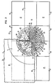
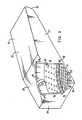
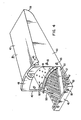
- FIG. 1 a portion of a shell 1 and tube 3 heat exchanger 5 with an inlet nozzle 7 extending from the shell 1.
- the nozzle 7 has a thermal lining 9, which extends to a wrapper 11 disposed between the shell 1 and the tubes 3.
- the flow distributor 13 in fluid communication with the shell side of the heat exchanger 5 and the inlet nozzle 7 is a flow distributor 13.
- the flow distributor 13 as shown in Figure 2 comprises a flow splitter portion 14 with a plurality of vanes 15 that extend radially from the axis of the inlet nozzle 7 to form a plurality, six, individual pie-shaped flow paths and a plurality, six, enclosures or chambers each of which is in fluid communication with only one of the individual pie-shaped flow paths.
- the six chambers or enclosures generally have two shapes, end chambers 17, as shown in Figure 3, and center chambers 19, as shown in Figure 4. There are four end chambers 17, however, two of these are mirror images of, or opposite hand from, those shown in Figure 3 and the two center chambers 19 are identical.
- the end chambers 17 comprise a plurality of plates joined together and sealed at their margins by welding or other means.
- a bottom plate 21 is generally flat along its length except one end which is bent upward so as to provide a large radius bend 23.
- the bottom plate 21 is perforated or has a plurality of apertures 25 disposed therein.
- the enclosures 17 have walls 27 generally normal to the bottom plate 21 on three sides and a top plate 29 generally parallel to the bottom plate 21.
- the top plate 29 is substantially shorter than the bottom plate 21 and there is an inclined plate 31 which extends from the turned-up margin of the bottom plate 21 to the top plate 29, all of these plates except the bottom plate 21 are imperforate.
- a perforated plate 33 is disposed within the chamber 17 generally parallel to the bottom plate 21 and spaced therefrom.
- the perforations in the perforated plate 33 are offset with respect to the perforations in the bottom plate 21 and produce a higher hydraulic resistance to flow than the perforations in the bottom plate 21.
- One corner of the chamber 17 is open forming a pie-shaped opening when looking down from the top plate 29.
- An arcuate collar 35 is disposed on the top plate adjacent said pie-shaped opening.
- the perforated plate 33 has such an opening but the bottom plate 21 does not.
- the walls 27 adjacent the opening have holes 36 disposed therein for receiving bolts or other fasteners to fasten adjacent chambers together.
- the width and height of the chambers are sufficiently small to allow the chambers 17 to be placed in the shell through the inlet nozzle 7, however the length of the bottom plate 21 is substantially longer than the diameter of the inlet nozzle 7 and its width is only slightly smaller than the diameter so each chamber distributes the influent fluid over a greater area than the projection of the inlet nozzle 7.
- a center chamber 19 comprising a plurality of plates joined together and sealed at their margins by welding or other means.
- a bottom plate 37 is generally flat along its length except one end which is bent upwardly so as to provide a large radius bend 39 and it is generally the same shape as the bottom plate 21.
- the bottom plate 37 also has perforations or apertures 41 spaced at regular intervals therein.
- Imperforate walls 43 attach to the bottom plate and generally extend normal thereto.
- a short top plate 45 is disposed generally parallel to the bottom plate and is connected to an inclined plate wall portion 47 which extends to the turned-up margin of the bottom plate 37.
- the top plate 49 has a circular margin from which a collar 49 extends.
- a perforated plate 51 is disposed within the chamber 19 generally parallel to the bottom plate 37. Perforations 52 in the perforated plate 51 are offset with respect to the perforations 41 in the bottom plate 37 and produce a higher hydraulic resistance to flow than the bottom perforated plate 37.
- a pair of flat bars 53 extend from the bottom plate 37 to the elevation of the perforated plate 51 forming a V and a pie-shaped opening in the space between the bottom plate 37 and the perforated plate 51.
- Holes 55 are disposed in the walls 43 for fastening the chambers 19 to the chambers 17 utilizing bolts and nuts or other fasteners.
- Figure 5 shows the flow splitter 14 which comprises a plurality of radially disposed vanes 15 disposed in a circular array to form a separate flow path for each chamber 17 or 19.
- a circular perforated plate 59 is disposed on one end of the vanes 57 and a ring 61 is disposed adjacent the opposite end of the vanes 15.
- a round bar 63 is disposed at the center of the vanes 15 providing a heavy segment to which the vanes 57 can be welded and the round bar 63 is drilled and tapped to provide an attachment for handling the flow splitter and assembled flow distributor.
- the method of installing the flow distributor 13 through the inlet nozzle 7 of the shell and tube heat exchanger comprises the steps of:
- the flow distributor 13 and method of installing it through the inlet nozzle 7 provides a feedwater flow pattern which reduces peak velocities and controls the direction of the flow into the heat exchanger so as to reduce tube vibration and potential localized tube wall thinning at support plate locations adjacent the inlet nozzle 7.
Landscapes
- Engineering & Computer Science (AREA)
- Physics & Mathematics (AREA)
- Thermal Sciences (AREA)
- Mechanical Engineering (AREA)
- General Engineering & Computer Science (AREA)
- Details Of Heat-Exchange And Heat-Transfer (AREA)
- Heat-Exchange Devices With Radiators And Conduit Assemblies (AREA)
Applications Claiming Priority (2)
| Application Number | Priority Date | Filing Date | Title |
|---|---|---|---|
| US06/413,584 US4576222A (en) | 1982-08-31 | 1982-08-31 | Fluid distributor for heat exchanger inlet nozzle |
| US413584 | 1982-08-31 |
Publications (2)
| Publication Number | Publication Date |
|---|---|
| EP0104347A2 true EP0104347A2 (de) | 1984-04-04 |
| EP0104347A3 EP0104347A3 (de) | 1984-10-03 |
Family
ID=23637813
Family Applications (1)
| Application Number | Title | Priority Date | Filing Date |
|---|---|---|---|
| EP83107152A Withdrawn EP0104347A3 (de) | 1982-08-31 | 1983-07-21 | Flüssigkeitsverteiler für einen Wärmetauschereinlassstutzen |
Country Status (5)
| Country | Link |
|---|---|
| US (1) | US4576222A (de) |
| EP (1) | EP0104347A3 (de) |
| JP (1) | JPS6026958B2 (de) |
| KR (1) | KR840006064A (de) |
| ES (1) | ES8505093A1 (de) |
Families Citing this family (20)
| Publication number | Priority date | Publication date | Assignee | Title |
|---|---|---|---|---|
| JP2952102B2 (ja) * | 1991-04-05 | 1999-09-20 | ウエスチングハウス・エレクトリック・コーポレイション | 熱交換器 |
| US5653282A (en) * | 1995-07-19 | 1997-08-05 | The M. W. Kellogg Company | Shell and tube heat exchanger with impingement distributor |
| CA2260157C (en) * | 1996-07-19 | 2003-03-18 | Steve S. Dingle | Evaporator refrigerant distributor |
| US6167713B1 (en) | 1999-03-12 | 2001-01-02 | American Standard Inc. | Falling film evaporator having two-phase distribution system |
| US6293112B1 (en) | 1999-12-17 | 2001-09-25 | American Standard International Inc. | Falling film evaporator for a vapor compression refrigeration chiller |
| US6835307B2 (en) | 2000-08-04 | 2004-12-28 | Battelle Memorial Institute | Thermal water treatment |
| US20070028647A1 (en) * | 2005-08-04 | 2007-02-08 | York International | Condenser inlet diffuser |
| DE102005055676A1 (de) * | 2005-11-22 | 2007-05-24 | Linde Ag | Wärmetauscher |
| US8365812B2 (en) * | 2007-06-27 | 2013-02-05 | King Fahd University Of Petroleum And Minerals | Shell and tube heat exchanger |
| US8240367B2 (en) | 2007-06-28 | 2012-08-14 | Exxonmobil Research And Engineering Company | Plate heat exchanger port insert and method for alleviating vibrations in a heat exchanger |
| US8276653B2 (en) * | 2008-03-28 | 2012-10-02 | Saudi Arabian Oil Company | Raised overlapped impingement plate |
| ITMI20100249U1 (it) | 2010-07-16 | 2012-01-17 | Alfa Laval Corp Ab | Dispositivo di scambio termico con sistema perfezionato di distribuzione del fluido refrigerante |
| DE102011013340A1 (de) * | 2010-12-30 | 2012-07-05 | Linde Aktiengesellschaft | Verteileinrichtung und Wärmetauschervorrichtung |
| EP2976587A4 (de) * | 2013-03-20 | 2017-03-15 | ConocoPhillips Company | Kältemitteleinlaufströmungsverteiler für kern-in-hülle-wärmetauscher |
| CN103307922A (zh) * | 2013-06-13 | 2013-09-18 | 盐城汇百实业有限公司 | 一种收槽分布板 |
| US10830510B2 (en) * | 2015-12-21 | 2020-11-10 | Johnson Controls Technology Company | Heat exchanger for a vapor compression system |
| JP6988209B2 (ja) * | 2017-07-11 | 2022-01-05 | 株式会社Ihi | 流体分散器及び流体分散装置 |
| US11412640B2 (en) * | 2019-07-29 | 2022-08-09 | Pratt & Whitney Canada Corp. | Plate cooler for aircraft electronic components |
| US12523429B2 (en) | 2023-11-02 | 2026-01-13 | Saudi Arabian Oil Company | Shell-side heat transfer enhancement |
| CN119803159B (zh) * | 2024-12-19 | 2025-10-10 | 安徽科希曼电器有限公司 | 一种用于壳管换热器的流量分配装置 |
Family Cites Families (22)
| Publication number | Priority date | Publication date | Assignee | Title |
|---|---|---|---|---|
| DE322789C (de) * | 1918-01-27 | 1920-07-08 | Norddeutsche Kuehlerfabrik G M | Wasserverteiler fuer Kuehler von Fahrzeugmotoren |
| US2830797A (en) * | 1953-05-05 | 1958-04-15 | Frick Co | Refrigerant condenser |
| US3042379A (en) * | 1959-06-29 | 1962-07-03 | Bell & Gossett Co | Condensers |
| US3070157A (en) * | 1959-10-05 | 1962-12-25 | C H Wheeler Mfg Co | Means for dissipating the energy of steam in large quantities |
| US3139926A (en) * | 1960-11-28 | 1964-07-07 | American Radiator & Standard | Surface condenser |
| US3338218A (en) * | 1965-10-22 | 1967-08-29 | Foster Wheeler Corp | Once-through boiler downcomer flow distribution system |
| JPS4425751Y1 (de) * | 1966-02-14 | 1969-10-28 | ||
| US3382918A (en) * | 1966-08-01 | 1968-05-14 | Ingersoll Rand Co | Reinforcing structure for direct flow steam dome for condensers |
| FR1583744A (de) * | 1967-12-08 | 1969-12-05 | ||
| DE1751489A1 (de) * | 1968-06-07 | 1971-07-08 | Aluminium U Metallwarenfabrik | Waermeaustauscher zur Verfluessigung oder Verdampfung von Kaeltemitteln |
| AT326706B (de) * | 1969-09-26 | 1975-12-29 | Waagner Biro Ag | Radialstromwärmetauscher |
| US3827484A (en) * | 1970-02-04 | 1974-08-06 | W Wolowodiuk | Liquid metal heat exchanger |
| US3706301A (en) * | 1971-07-13 | 1972-12-19 | Combustion Eng | Integral economizer for u-tube generator |
| US3895674A (en) * | 1972-02-24 | 1975-07-22 | Us Energy | Inlet flow distributor for a heat exchanger |
| SU777391A1 (ru) * | 1974-02-01 | 1980-11-07 | Предприятие П/Я Г-4285 | Входна камера теплообменника |
| JPS529A (en) * | 1975-06-20 | 1977-01-05 | Fudo Construction Co | Method of feeding aggregate for improving subsoil |
| US4016835A (en) * | 1975-08-01 | 1977-04-12 | Southwestern Engineering Company | Moisture separator-reheater |
| US4166497A (en) * | 1976-01-21 | 1979-09-04 | Westinghouse Electric Corp. | Apparatus for increasing effective scavenging vent steam within a heat exchanger which condenses vapor inside long tubes |
| DE2605186A1 (de) * | 1976-02-10 | 1977-08-11 | Kraftwerk Union Ag | Dampfeinstroemvorrichtung fuer behaelter mit einer umlenkstelle fuer sattdampf |
| FR2363772A1 (fr) * | 1976-09-03 | 1978-03-31 | Commissariat Energie Atomique | Echangeur de chaleur, notamment generateur de vapeur chauffe au sodium liquide |
| FR2402176A2 (fr) * | 1977-09-05 | 1979-03-30 | Commissariat Energie Atomique | Echangeur de chaleur, notamment generateur de vapeur chauffe au sodium liquide |
| JPS5844198B2 (ja) * | 1978-10-05 | 1983-10-01 | 株式会社日立製作所 | 多管式熱交換器 |
-
1982
- 1982-08-31 US US06/413,584 patent/US4576222A/en not_active Expired - Fee Related
-
1983
- 1983-07-21 EP EP83107152A patent/EP0104347A3/de not_active Withdrawn
- 1983-08-12 JP JP58146823A patent/JPS6026958B2/ja not_active Expired
- 1983-08-24 KR KR1019830003956A patent/KR840006064A/ko not_active Withdrawn
- 1983-08-30 ES ES525240A patent/ES8505093A1/es not_active Expired
Also Published As
| Publication number | Publication date |
|---|---|
| JPS6026958B2 (ja) | 1985-06-26 |
| ES525240A0 (es) | 1985-03-01 |
| US4576222A (en) | 1986-03-18 |
| JPS5993102A (ja) | 1984-05-29 |
| KR840006064A (ko) | 1984-11-21 |
| EP0104347A3 (de) | 1984-10-03 |
| ES8505093A1 (es) | 1985-03-01 |
Similar Documents
| Publication | Publication Date | Title |
|---|---|---|
| EP0104347A2 (de) | Flüssigkeitsverteiler für einen Wärmetauschereinlassstutzen | |
| RU2004115336A (ru) | Теплообменник для изотермических химических реакторов | |
| US4105067A (en) | Device for locating a layer of tubes in an enclosure | |
| US4645001A (en) | Heat exchanger | |
| GB2082312A (en) | Header tank construction | |
| US4325171A (en) | Means and method for sealing heat exchanger walls | |
| US3830292A (en) | Flow distribution for heat exchangers | |
| US5273002A (en) | Water tube boiler | |
| GB1422695A (en) | Heat exchanger tube supports | |
| CA1096853A (en) | Plate-type heat exchanger | |
| GB1578629A (en) | Radiation and convection heating unit | |
| US3139926A (en) | Surface condenser | |
| GB1226429A (de) | ||
| JPS62131103A (ja) | 熱交換器のための管および支持装置 | |
| SE9801192D0 (sv) | Värmeväxlaranläggning | |
| SU872936A1 (ru) | Кожухотрубный теплообменник | |
| JPH10122771A5 (de) | ||
| RU2008571C1 (ru) | Радиатор | |
| GB2049126A (en) | Boiler | |
| JPH03134491A (ja) | 熱交換器 | |
| SU1128093A1 (ru) | Пластинчато-трубный теплообменник | |
| US20050092219A1 (en) | Fluidized bed boiler furnace comprising two hearths separated by an inside leg area | |
| JPS602466Y2 (ja) | 多管式熱交換器 | |
| JP2673306B2 (ja) | 角型多管式貫流ボイラ | |
| JPS58178195A (ja) | 熱交換器 |
Legal Events
| Date | Code | Title | Description |
|---|---|---|---|
| PUAI | Public reference made under article 153(3) epc to a published international application that has entered the european phase |
Free format text: ORIGINAL CODE: 0009012 |
|
| AK | Designated contracting states |
Designated state(s): BE CH DE FR IT LI |
|
| PUAL | Search report despatched |
Free format text: ORIGINAL CODE: 0009013 |
|
| AK | Designated contracting states |
Designated state(s): BE CH DE FR IT LI |
|
| 17P | Request for examination filed |
Effective date: 19850320 |
|
| STAA | Information on the status of an ep patent application or granted ep patent |
Free format text: STATUS: THE APPLICATION IS DEEMED TO BE WITHDRAWN |
|
| 18D | Application deemed to be withdrawn |
Effective date: 19870128 |
|
| RIN1 | Information on inventor provided before grant (corrected) |
Inventor name: GRANATA, SAMUEL JOSEPH, JR. Inventor name: RYLATT, JOHN ANTHONY |