EP0104360A2 - Outil d'enfoncement électromagnétique - Google Patents
Outil d'enfoncement électromagnétique Download PDFInfo
- Publication number
- EP0104360A2 EP0104360A2 EP83107492A EP83107492A EP0104360A2 EP 0104360 A2 EP0104360 A2 EP 0104360A2 EP 83107492 A EP83107492 A EP 83107492A EP 83107492 A EP83107492 A EP 83107492A EP 0104360 A2 EP0104360 A2 EP 0104360A2
- Authority
- EP
- European Patent Office
- Prior art keywords
- hollow cylinder
- plunger
- valve flap
- wrapping device
- wrapping
- Prior art date
- Legal status (The legal status is an assumption and is not a legal conclusion. Google has not performed a legal analysis and makes no representation as to the accuracy of the status listed.)
- Granted
Links
- 238000004026 adhesive bonding Methods 0.000 claims 1
- 239000013013 elastic material Substances 0.000 claims 1
- 230000035939 shock Effects 0.000 claims 1
- 230000007257 malfunction Effects 0.000 abstract description 2
- 239000000872 buffer Substances 0.000 description 4
- 230000008901 benefit Effects 0.000 description 2
- 239000007853 buffer solution Substances 0.000 description 2
- 238000013016 damping Methods 0.000 description 2
- 230000009471 action Effects 0.000 description 1
- 238000010276 construction Methods 0.000 description 1
- 238000011161 development Methods 0.000 description 1
- 230000018109 developmental process Effects 0.000 description 1
- 230000000694 effects Effects 0.000 description 1
- 238000012423 maintenance Methods 0.000 description 1
- 230000032258 transport Effects 0.000 description 1
Images
Classifications
-
- B—PERFORMING OPERATIONS; TRANSPORTING
- B25—HAND TOOLS; PORTABLE POWER-DRIVEN TOOLS; MANIPULATORS
- B25C—HAND-HELD NAILING OR STAPLING TOOLS; MANUALLY OPERATED PORTABLE STAPLING TOOLS
- B25C1/00—Hand-held nailing tools; Nail feeding devices
- B25C1/06—Hand-held nailing tools; Nail feeding devices operated by electric power
Definitions
- the invention is based on a wrapping device according to the type of the main claim.
- Such an impact device is already known, in which, after the tappet has been hammered in, a spring is used to return it to its starting position.
- a rubber buffer catches the returning plunger at the end of its return.
- This has the disadvantage that the energy stored when the plunger is intercepted by the rubber buffer often throws the plunger back so far in its working direction that an impact knife connected to it detaches the next available fastening means from the magazine and transports it a little way into the guide channel to the impact point. Only then does the tappet come to rest in its end position on the rubber buffer.
- the impact knife releases another fastener from the magazine, which strikes the fastener already in the guide channel. This is how malfunctions are caused.
- a buffer system intended to destroy excess impact energy according to EU patent application 0054782 could possibly remedy this.
- This buffer system is relatively complex, takes up a lot of space and wears out relatively quickly. This makes it necessary to replace the buffer element, which also requires appropriate structural precaution and careful maintenance of the device.
- the wrapping device according to the invention with the characterizing features of the main claim has the advantage that its air damper is simply the same in construction and in life as the other components of the device. In addition, less space is required for this air damper.
- the combination of the air damper with the check valve ensures an ideal working cycle of undamped impact movement and damped return stroke.
- the measures listed in the subclaims permit advantageous developments and improvements of the wrapping device specified in the main claim.
- the design of the air damper as a tappet guide is particularly advantageous. This saves additional guide parts.
- the design with a hollow cylinder onto which a cup-shaped tappet is pushed results in an ideal damping characteristic with a damping effect that increases towards the end of the return stroke movement.
- FIG. 1 An embodiment of the subject of the invention is shown in the drawing and explained in more detail in the following description.
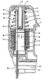
- the figure shows a longitudinal cut through an impact device according to the invention.
- a coil 2 is arranged through the cylindrical interior 3 of which a cup-shaped tappet 4 and a pusher knife 5 fixedly connected thereto are displaceably guided.
- the plunger 4 is additionally axially displaceable on a hollow cylinder 6.
- the widened base 7 of the hollow cylinder 6 is firmly connected to the device housing 1.
- An opening 8 in the device housing 1 connects the interior of the hollow cylinder 6 with the outside air.
- a valve flap 9 is fastened in such a way that it allows air flowing in from the outside to pass freely, but prevents the air from escaping from the housing.
- the space around the plunger 4 is also vented to the outside, which is represented by an opening 10 in the device housing 1.
- a conical coil spring 11 is supported against a spring ring 12 at the end of the plunger 4 and a washer 13 slid onto the plunger 4 in front of it.
- the abutment for this helical spring 11 is formed by a rib 14 of the device housing 1.
- the lower end of the impact knife 5 in the drawing is guided in a guide channel 15.
- a magazine guide 16 for a fastener magazine 17 leads at right angles to the guide channel 15.
- a fastening means is introduced into the guide channel 15 in front of the butt knife 5.
- the tappet 4 When a voltage pulse is applied to the coil 2, the tappet 4 is quickly drawn into the interior 3 of the coil by the resulting magnetic field (arrow 18).
- the butt knife 5 is moved through the guide channel 15, detaches a fastener from the fastener magazine 17 and drives it into a workpiece lying in front of the end of the guide channel 15.
- the tappet 4 sucked in outside air through the opening 8 and the interior of the hollow cylinder 6, the valve flap 9 allowing this outside air to enter unhindered.
- the impact movement was therefore not hindered by the air damper formed from the plunger 4 and the hollow cylinder 6.
- the magnetic field which collapses at the end of the voltage pulse releases the plunger 4 again, so that it can be moved back into its starting position under the action of the helical spring 11.
- the air in the interior of the plunger 4 is slowly pressed through a throttle gap 19 formed between the plunger 4 and the hollow cylinder 6, because the valve flap 9, which now closes the interior of the hollow cylinder 6, does not permit unhindered escape of the air to the outside.
- the return stroke movement in the direction of an arrow 20 is damped and prevents the plunger 4 from rebounding from its contact surface on the base 7 of the hollow cylinder 6. This ensures that the wrapping device functions properly.
Landscapes
- Engineering & Computer Science (AREA)
- Mechanical Engineering (AREA)
- Portable Nailing Machines And Staplers (AREA)
- Magnetically Actuated Valves (AREA)
Applications Claiming Priority (2)
| Application Number | Priority Date | Filing Date | Title |
|---|---|---|---|
| DE3232120 | 1982-08-28 | ||
| DE19823232120 DE3232120A1 (de) | 1982-08-28 | 1982-08-28 | Elektromagnetisch betriebenes einschlaggeraet |
Publications (3)
| Publication Number | Publication Date |
|---|---|
| EP0104360A2 true EP0104360A2 (fr) | 1984-04-04 |
| EP0104360A3 EP0104360A3 (en) | 1985-07-03 |
| EP0104360B1 EP0104360B1 (fr) | 1987-10-28 |
Family
ID=6171976
Family Applications (1)
| Application Number | Title | Priority Date | Filing Date |
|---|---|---|---|
| EP83107492A Expired EP0104360B1 (fr) | 1982-08-28 | 1983-07-29 | Outil d'enfoncement électromagnétique |
Country Status (5)
| Country | Link |
|---|---|
| US (1) | US4515303A (fr) |
| EP (1) | EP0104360B1 (fr) |
| JP (1) | JPS5959361A (fr) |
| BR (1) | BR8304632A (fr) |
| DE (2) | DE3232120A1 (fr) |
Cited By (5)
| Publication number | Priority date | Publication date | Assignee | Title |
|---|---|---|---|---|
| FR2571294A1 (fr) * | 1984-10-09 | 1986-04-11 | Bosch Gmbh Robert | Appareil a choc a manoeuvre electromagnetique comportant un amortisseur pneumatique |
| FR2583715A1 (fr) * | 1985-06-12 | 1986-12-26 | Lai Wen Tah | Agrafeuse a force d'impact accrue, comportant un dispositif absorbant la force de rebondissement |
| DE102004008959A1 (de) * | 2004-02-24 | 2005-09-08 | Aplus Pneumatic Corp. | Nagel-Tacker |
| WO2015169167A1 (fr) * | 2014-05-05 | 2015-11-12 | 北京大风时代科技有限责任公司 | Cloueuse électromagnétique |
| CN105451944A (zh) * | 2013-07-31 | 2016-03-30 | 日立工机株式会社 | 打入机 |
Families Citing this family (18)
| Publication number | Priority date | Publication date | Assignee | Title |
|---|---|---|---|---|
| DE3405906A1 (de) * | 1984-02-18 | 1985-08-22 | Robert Bosch Gmbh, 7000 Stuttgart | Eintreibgeraet fuer befestigungsmittel, insbesondere elektrotacker |
| US4940177A (en) * | 1988-12-30 | 1990-07-10 | Jimena Carlos L | Electric stapler having electronic control circuit |
| GB2275227B (en) * | 1993-02-23 | 1996-11-13 | Tohoku Ricoh Co Limited | Stencil duplication machine |
| DE19728176A1 (de) * | 1997-07-02 | 1999-01-07 | Hilti Ag | Setzgerät |
| WO2002016085A1 (fr) | 2000-08-25 | 2002-02-28 | Barber John P | Dispositif a chocs |
| US6783051B2 (en) * | 2002-01-15 | 2004-08-31 | The Fletcher-Terry Company | Point driver |
| US20040159695A1 (en) * | 2002-08-23 | 2004-08-19 | Chu-Kuo Wang | Nail stapler |
| US6742691B2 (en) * | 2002-08-23 | 2004-06-01 | Mu-Yu Chen | Nail stapler |
| US6662990B1 (en) * | 2003-01-03 | 2003-12-16 | Modern Pioneer Ltd. | Buffer apparatus of electrical nailing gun |
| CN2644112Y (zh) * | 2003-07-04 | 2004-09-29 | 益卓有限公司 | 电动钉枪 |
| US6857549B1 (en) * | 2003-11-21 | 2005-02-22 | Navtor Technology Corporation | Nail driving gun with a shock-absorbing member |
| US7503400B2 (en) * | 2004-01-30 | 2009-03-17 | Arrow Fastener Co., Inc. | Two shot power nailer |
| GB2411143B (en) * | 2004-02-19 | 2005-12-28 | Aplus Pneumatic Corp | Nail stapler |
| US9071120B2 (en) * | 2011-07-19 | 2015-06-30 | Kanzaki Kokyukoki Mfg. Co., Ltd. | Linear actuator and boring device |
| JP5991425B2 (ja) | 2013-03-29 | 2016-09-14 | 日立工機株式会社 | 打込機 |
| US12202112B2 (en) | 2021-01-20 | 2025-01-21 | Milwaukee Electric Tool Corporation | Powered fastener driver |
| WO2022159538A1 (fr) | 2021-01-20 | 2022-07-28 | Milwaukee Electric Tool Corporation | Dispositif d'entraînement d'élément de fixation électrique |
| US12263568B2 (en) * | 2021-09-15 | 2025-04-01 | Robert Bosch Power Tools GmbH | Head valve system for air spring power tool |
Family Cites Families (8)
| Publication number | Priority date | Publication date | Assignee | Title |
|---|---|---|---|---|
| US1853695A (en) * | 1930-02-25 | 1932-04-12 | Clarence M Griggs | Pneumatic improvement for solenoid hammers |
| GB920586A (en) * | 1960-09-21 | 1963-03-06 | Bourcier Carbon Christian | Improvements in or relating to pneumatic shock absorbers |
| US3434026A (en) * | 1966-12-12 | 1969-03-18 | Fastener Corp | Electrically operated reciprocating tool |
| CA1039001A (fr) * | 1975-02-13 | 1978-09-26 | Duo-Fast Corporation | Outil cloueur electrique |
| US4183453A (en) * | 1977-04-10 | 1980-01-15 | Swingline, Inc. | Electronically operated portable fastener driving tool |
| DE2729002C3 (de) * | 1977-06-28 | 1981-08-13 | Erwin Müller GmbH & Co, 4450 Lingen | Heft- oder Nagelgerät dessen Eintreibstößel während seines Arbeitshubes mittels Tauchanker und Magnetspule antreibbar ist |
| CA1124366A (fr) * | 1977-10-04 | 1982-05-25 | Edward E. Barrett | Outil de serrage portatif a commande electronique |
| DE3047662C2 (de) * | 1980-12-18 | 1985-02-21 | Karl M. Reich Maschinenfabrik GmbH, 7440 Nürtingen | Puffersystem bei Einschlaggeräten |
-
1982
- 1982-08-28 DE DE19823232120 patent/DE3232120A1/de not_active Withdrawn
-
1983
- 1983-06-10 US US06/503,176 patent/US4515303A/en not_active Expired - Fee Related
- 1983-07-29 EP EP83107492A patent/EP0104360B1/fr not_active Expired
- 1983-07-29 DE DE8383107492T patent/DE3374184D1/de not_active Expired
- 1983-08-26 BR BR8304632A patent/BR8304632A/pt not_active IP Right Cessation
- 1983-08-29 JP JP58156549A patent/JPS5959361A/ja active Granted
Cited By (6)
| Publication number | Priority date | Publication date | Assignee | Title |
|---|---|---|---|---|
| FR2571294A1 (fr) * | 1984-10-09 | 1986-04-11 | Bosch Gmbh Robert | Appareil a choc a manoeuvre electromagnetique comportant un amortisseur pneumatique |
| FR2583715A1 (fr) * | 1985-06-12 | 1986-12-26 | Lai Wen Tah | Agrafeuse a force d'impact accrue, comportant un dispositif absorbant la force de rebondissement |
| DE102004008959A1 (de) * | 2004-02-24 | 2005-09-08 | Aplus Pneumatic Corp. | Nagel-Tacker |
| CN105451944A (zh) * | 2013-07-31 | 2016-03-30 | 日立工机株式会社 | 打入机 |
| CN105451944B (zh) * | 2013-07-31 | 2017-12-12 | 日立工机株式会社 | 打入机 |
| WO2015169167A1 (fr) * | 2014-05-05 | 2015-11-12 | 北京大风时代科技有限责任公司 | Cloueuse électromagnétique |
Also Published As
| Publication number | Publication date |
|---|---|
| DE3232120A1 (de) | 1984-03-01 |
| US4515303A (en) | 1985-05-07 |
| DE3374184D1 (en) | 1987-12-03 |
| EP0104360B1 (fr) | 1987-10-28 |
| EP0104360A3 (en) | 1985-07-03 |
| JPS5959361A (ja) | 1984-04-05 |
| BR8304632A (pt) | 1984-04-03 |
| JPH0474149B2 (fr) | 1992-11-25 |
Similar Documents
| Publication | Publication Date | Title |
|---|---|---|
| EP0104360A2 (fr) | Outil d'enfoncement électromagnétique | |
| DE2838194C3 (de) | Vorrichtung zum Zuführen und Vereinzeln von Befestigungsmitteln | |
| DE1426740C3 (de) | Hubkolbenkraftmaschine | |
| DE2641070C2 (fr) | ||
| CH662977A5 (de) | Bohrhammer. | |
| DE1964033U (de) | Hydraulischer stossdaempfer. | |
| DE3437019C2 (de) | Elektromagnetisch betriebenes Einschlaggerät mit einem Luftdämpfer | |
| DE3111065C2 (fr) | ||
| DE861360C (de) | Luftfederung bzw. pneumatischer Stossdaempfer fuer Fahrzeuge mit einem innerhalb eines Zylinders beweglichen Plunger | |
| DE1936858B2 (de) | Selbstpumpendes hydraulisches Federbein mit innerer Niveauregelung für Fahrzeuge | |
| DE3228040C1 (de) | Sauggreifeinrichtung | |
| DE1265678B (de) | Geraet zum Eintreiben von Klammern oder aehnlichen Befestigungsmitteln in ein Werkstueck | |
| DE3886658T2 (de) | Pneumatisch betriebene Vorrichtung und Verfahren zur Verwendung. | |
| DE29616054U1 (de) | Möbelauszug mit Selbsteinzug | |
| DE1147540B (de) | Mit Druckluft betriebenes Geraet zum Einschlagen von Heftklammern, Naegeln od. dgl. | |
| EP1043497B1 (fr) | Soupape de commande | |
| DE102005015216B4 (de) | Dämpfungseinrichtung für Linearantriebe | |
| DE2845324C3 (de) | Kraftstoffeinspritzpumpe für Brennkraftmaschinen | |
| DE9216394U1 (de) | Treiberabdichtung an einem mit Druckluft betriebenen Gerät zum Eintreiben von Befestigungsmitteln | |
| DE102015013422A1 (de) | Dämpfungselement | |
| AT220102B (de) | Motorisch angetriebener Hammer | |
| DE828201C (de) | Fluessigkeits-Stossdaempfer, insbesondere fuer Kraftfahrzeuge | |
| DE2250475C3 (de) | Steuerventileinrichtung für den doppelt wirkenden Arbeitszylinder eines mit Druckluft betriebenen Schlaggeräts | |
| DE880165C (de) | Daempfungsvorrichtung fuer elektromagnetische Schlaggeraete | |
| AT220323B (de) | Hydraulische Hubvorrichtung |
Legal Events
| Date | Code | Title | Description |
|---|---|---|---|
| PUAI | Public reference made under article 153(3) epc to a published international application that has entered the european phase |
Free format text: ORIGINAL CODE: 0009012 |
|
| 17P | Request for examination filed |
Effective date: 19830729 |
|
| AK | Designated contracting states |
Designated state(s): DE FR GB |
|
| PUAL | Search report despatched |
Free format text: ORIGINAL CODE: 0009013 |
|
| AK | Designated contracting states |
Designated state(s): DE FR GB |
|
| 17Q | First examination report despatched |
Effective date: 19860616 |
|
| GRAA | (expected) grant |
Free format text: ORIGINAL CODE: 0009210 |
|
| AK | Designated contracting states |
Kind code of ref document: B1 Designated state(s): DE FR GB |
|
| REF | Corresponds to: |
Ref document number: 3374184 Country of ref document: DE Date of ref document: 19871203 |
|
| ET | Fr: translation filed | ||
| GBT | Gb: translation of ep patent filed (gb section 77(6)(a)/1977) | ||
| PLBE | No opposition filed within time limit |
Free format text: ORIGINAL CODE: 0009261 |
|
| STAA | Information on the status of an ep patent application or granted ep patent |
Free format text: STATUS: NO OPPOSITION FILED WITHIN TIME LIMIT |
|
| 26N | No opposition filed | ||
| REG | Reference to a national code |
Ref country code: FR Ref legal event code: D6 |
|
| REG | Reference to a national code |
Ref country code: GB Ref legal event code: 746 Effective date: 19951207 |
|
| REG | Reference to a national code |
Ref country code: GB Ref legal event code: IF02 |
|
| PGFP | Annual fee paid to national office [announced via postgrant information from national office to epo] |
Ref country code: GB Payment date: 20020711 Year of fee payment: 20 |
|
| PGFP | Annual fee paid to national office [announced via postgrant information from national office to epo] |
Ref country code: FR Payment date: 20020723 Year of fee payment: 20 |
|
| PGFP | Annual fee paid to national office [announced via postgrant information from national office to epo] |
Ref country code: DE Payment date: 20020826 Year of fee payment: 20 |
|
| PG25 | Lapsed in a contracting state [announced via postgrant information from national office to epo] |
Ref country code: GB Free format text: LAPSE BECAUSE OF EXPIRATION OF PROTECTION Effective date: 20030728 |
|
| REG | Reference to a national code |
Ref country code: GB Ref legal event code: PE20 |