EP0104363A1 - Valve de commande de pression, notamment valve de commande à pied pour véhicules à moteur - Google Patents
Valve de commande de pression, notamment valve de commande à pied pour véhicules à moteur Download PDFInfo
- Publication number
- EP0104363A1 EP0104363A1 EP83107548A EP83107548A EP0104363A1 EP 0104363 A1 EP0104363 A1 EP 0104363A1 EP 83107548 A EP83107548 A EP 83107548A EP 83107548 A EP83107548 A EP 83107548A EP 0104363 A1 EP0104363 A1 EP 0104363A1
- Authority
- EP
- European Patent Office
- Prior art keywords
- piston
- spring
- pressure
- control valve
- pressure control
- Prior art date
- Legal status (The legal status is an assumption and is not a legal conclusion. Google has not performed a legal analysis and makes no representation as to the accuracy of the status listed.)
- Withdrawn
Links
- 125000006850 spacer group Chemical group 0.000 claims 1
- 238000005303 weighing Methods 0.000 description 3
- 238000010276 construction Methods 0.000 description 2
- 238000011161 development Methods 0.000 description 1
- 230000018109 developmental process Effects 0.000 description 1
- 238000006073 displacement reaction Methods 0.000 description 1
- 230000000694 effects Effects 0.000 description 1
- 230000000284 resting effect Effects 0.000 description 1
- 238000007789 sealing Methods 0.000 description 1
- 230000001360 synchronised effect Effects 0.000 description 1
Images

Classifications
-
- B—PERFORMING OPERATIONS; TRANSPORTING
- B60—VEHICLES IN GENERAL
- B60T—VEHICLE BRAKE CONTROL SYSTEMS OR PARTS THEREOF; BRAKE CONTROL SYSTEMS OR PARTS THEREOF, IN GENERAL; ARRANGEMENT OF BRAKING ELEMENTS ON VEHICLES IN GENERAL; PORTABLE DEVICES FOR PREVENTING UNWANTED MOVEMENT OF VEHICLES; VEHICLE MODIFICATIONS TO FACILITATE COOLING OF BRAKES
- B60T15/00—Construction arrangement, or operation of valves incorporated in power brake systems and not covered by groups B60T11/00 or B60T13/00
- B60T15/02—Application and release valves
- B60T15/04—Driver's valves
- B60T15/043—Driver's valves controlling service pressure brakes
- B60T15/045—Driver's valves controlling service pressure brakes in multiple circuit systems, e.g. dual circuit systems
- B60T15/046—Driver's valves controlling service pressure brakes in multiple circuit systems, e.g. dual circuit systems with valves mounted in tandem
Definitions
- the invention relates to a pressure control valve according to the preamble of claim 1.
- a pressure piece is generally provided which can be mechanically acted on by means of a tread plate and in turn acts via a stepped plastic spring on a piston which is provided for actuating the inlet and outlet valve of the first brake circuit.
- a plastic spring alone can be problematic, especially when used under extreme temperature conditions, since the behavior of the stepped spring cannot be determined exactly as a function of temperature. If the stepped spring fails, it is no longer possible to brake appropriately with such foot brake valves, i.e. neither the first brake circuit nor the second brake circuit can be supplied with the brake pressure that may be required.
- Foot brake valves have already been developed (DE-OS 24 45 700), in which a combination of plastic spring and conventional coil spring is used. Even with such foot brake valves, there is the problem that the plastic spring can only be determined to a limited extent with regard to its gradability and that if one of the springs fails - plastic spring or coil spring - an adequate function of the first and the second brake circuit is no longer ensured.
- the object of the invention is to design a pressure control valve, in particular a foot brake valve of the generic type, in such a way that a limiting pressure, i.e. the maximum brake pressure at the outlet can be reached unchanged in both circles, even if a step spring breaks.
- a limiting pressure i.e. the maximum brake pressure at the outlet can be reached unchanged in both circles, even if a step spring breaks.
- the prescribed limiting pressure In the event of failure of a circuit with the circuit intact, it should also be possible to achieve the prescribed limiting pressure. If the device is intact, it should be possible to achieve the most accurate possible pressure-displacement-force assignment over the entire range, both at lower and at higher temperatures. All of these functional advantages should be achieved in a valve of short construction.
- the characteristic of the brake valve is flatter in the last section. This has the advantage that the set limiting pressure changes only slightly if changes occur later on the limiting elements or if the stepped springs settle. Furthermore, the limiting pressure can be set more easily.
- the foot brake valve is functional under almost all operating conditions, i.e. even if one of the circles fails and / or if one of the two stepped springs in the first circle breaks.
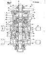
- a pressure control valve is shown as a double-circuit foot brake valve 1.
- a brake pedal (not shown) acts on a pressure piece 3.
- the pressure piece 3 is supported on a spring plate 5 and acts via a step spring 7 applied to the underside of the spring plate 5 on a piston 9, which is guided in the housing 11 of the foot brake valve 1 so as to be axially displaceable under sealing.
- an auxiliary piston 13 which is guided with a seal relative to the radially outer piston 9 and is pretensioned by a smaller spring 15, as will be explained in detail below.
- the H ilfskolben 13 acts by means of a projection formed thereon at 17 is directed downward movement in a known manner against an inlet and outlet valve 19 of the first circle, dh.des first brake circuit of the foot brake.
- the supply 21 of the first circuit is connected via a connection 23 to a reservoir chamber 25 of the F ußbrems- valve, while the cylinder arrangement of the first circuit by means of connection 29 of the foot brake valve is communicated with the brake chamber 31 in connection 27th
- Corresponding connections 33 and 35 are assigned to the second circuit of the foot brake valve and are connected to a supply or a brake cylinder arrangement.
- a so-called weighing piston 39 acts on the inlet and outlet valve 37 belonging to the second circuit; the weighing piston is either designed as a one-piece relay piston or, according to the exemplary embodiment in FIG. 1, consists of an inner relay piston 41 and an outer relay piston 43.
- the weighing piston 39 can be acted upon in a manner known per se by the compressed air of the brake chamber 31 of the first circuit in order to act on the inlet and outlet valve 37 of the second circuit in such a way that the corresponding supply comes into connection with the brake cylinder arrangement.
- the spring arrangement associated with the first brake circuit according to the invention which consists of the outer stepped spring 7 and the radially inner, smaller and also stepped spring 15, is constructed in such a way that the effect of the first circle and therefore also of the second circle is ensured even then, if one of the two springs breaks.
- the inner spring 15 is supported on an annular body 45, which is to be regarded as part of the piston 9.
- the step spring 7 and the spring 15 are arranged in series.
- the inner spring 15 is biased.
- the auxiliary piston 13 being held by a retaining ring 47 or the like supporting element engaging in the inner circumference of the piston 9. The auxiliary piston 13 is able to perform a relative movement upwards as shown in FIG.
- the distance S 1 according to FIG. 1 is available for the relative movement between the auxiliary piston and the piston, the auxiliary piston resting against the stop 49 of the piston.
- a relative movement between the pressure piece 3 and the piston 9 is possible, since an extension 51 formed on the pressure piece 3 or a threaded pin 53 arranged centrally on the piston 9 can move relative to one another by the distance S 2 until they assume a stop position .
- a ring 55 is screwed onto the pressure piece 3 and can be fixed in position by means of a nut 57 or the like securing element. In this way, the ring 55 serves as a stop element, that is, when the pressure piece 3 moves downward, it rests against the housing cover 59 forming the upper side of the housing 11.
- the distance between the ring 55 and the housing cover 59 is set to the value S F + h 1 / in the present exemplary embodiment, the value SF corresponding to the sum of the spring travel SF1 and S F2 and h 1 the distance (in the non-actuated state) between forms the lower edge of the extension 17 and the upper edge of the seal 61 of the valve body 63.
- S F1 is the spring travel of the stepped spring 7 at maximum braking pressure; accordingly, S F2 is the spring travel of the equally stepped spring 15 connected in series at maximum braking pressure.
- the stepped spring 7, together with the likewise stepped spring 15, forms an arrangement which is also functional when a failure of one of the both stepped springs or one of the circles of the foot brake valve is present.
- the auxiliary piston 13 is first displaced by the path S 1 when the pressure piece is actuated and rests against the stop 49.
- the characteristic curve according to FIG. 3 runs after this free travel with the same inclination as in FIG. 2, but without a kink.
- both pistons ie the piston 9 and the auxiliary piston 13 are shifted downward as shown in FIG. 1.
- the distance S 2 can be adjusted from below by means of the threaded pin 53.
- the force on the pressure piece 3 is not reduced, since the pressure in the brake chamber 31 also acts on the piston 9.
- the second circuit is set in a known manner mechanically via the inner relay piston in function.
- the outer relay piston which is designed as an annular piston, retains its position unchanged.
- the diameter of the inner relay piston 41 is preferably selected so that the same maximum braking pressure in the second circuit is achieved in the case of full braking as when the valve is intact.
- the free travel on the pressure piece 3 is increased by the play a and the exhaust stroke h 2 (characteristic curve in FIG. 3).
- the outer relay piston can be dispensed with in a known manner. It is also possible to provide a so-called synchronous device of known construction in the foot brake valve shown in FIG. 1.
Landscapes
- Engineering & Computer Science (AREA)
- Transportation (AREA)
- Mechanical Engineering (AREA)
- Valves And Accessory Devices For Braking Systems (AREA)
Applications Claiming Priority (2)
| Application Number | Priority Date | Filing Date | Title |
|---|---|---|---|
| DE19823231978 DE3231978A1 (de) | 1982-08-27 | 1982-08-27 | Druckregelventil, insbesondere fussbremsventil fuer kraftfahrzeuge |
| DE3231978 | 1982-08-27 |
Publications (1)
| Publication Number | Publication Date |
|---|---|
| EP0104363A1 true EP0104363A1 (fr) | 1984-04-04 |
Family
ID=6171892
Family Applications (1)
| Application Number | Title | Priority Date | Filing Date |
|---|---|---|---|
| EP83107548A Withdrawn EP0104363A1 (fr) | 1982-08-27 | 1983-08-01 | Valve de commande de pression, notamment valve de commande à pied pour véhicules à moteur |
Country Status (2)
| Country | Link |
|---|---|
| EP (1) | EP0104363A1 (fr) |
| DE (1) | DE3231978A1 (fr) |
Cited By (3)
| Publication number | Priority date | Publication date | Assignee | Title |
|---|---|---|---|---|
| JPS61241506A (ja) * | 1985-02-08 | 1986-10-27 | ヒグラマ・アクチエンゲゼルシヤフト | 圧力媒体シリンダ |
| EP0241436A1 (fr) * | 1986-04-02 | 1987-10-14 | INDUSTRIE MAGNETI MARELLI S.r.l. | Valve pneumatique pour systèmes de freinage |
| GB2193547A (en) * | 1986-08-09 | 1988-02-10 | Bendix Ltd | Dual circuit air brake valve |
Citations (4)
| Publication number | Priority date | Publication date | Assignee | Title |
|---|---|---|---|---|
| DE1120294B (de) * | 1959-02-17 | 1961-12-21 | Knorr Bremse Gmbh | Bremsventil, insbesondere zum Steuern der Druckluftbremsanlage von Lastkraftzuegen |
| DE2445700A1 (de) * | 1974-09-25 | 1976-04-08 | Wabco Westinghouse Gmbh | Bremsventil fuer zweikreis-druckluftbremsanlagen in motorfahrzeugen, insbesondere fuer hochdruck-bremsanlagen |
| DE2716495B1 (de) * | 1977-04-14 | 1978-07-06 | Wabco Westinghouse Gmbh | Druckregelventil |
| DE3022435A1 (de) * | 1980-06-14 | 1982-01-07 | Knorr-Bremse GmbH, 8000 München | Zweikreis-bremsventil |
-
1982
- 1982-08-27 DE DE19823231978 patent/DE3231978A1/de not_active Withdrawn
-
1983
- 1983-08-01 EP EP83107548A patent/EP0104363A1/fr not_active Withdrawn
Patent Citations (4)
| Publication number | Priority date | Publication date | Assignee | Title |
|---|---|---|---|---|
| DE1120294B (de) * | 1959-02-17 | 1961-12-21 | Knorr Bremse Gmbh | Bremsventil, insbesondere zum Steuern der Druckluftbremsanlage von Lastkraftzuegen |
| DE2445700A1 (de) * | 1974-09-25 | 1976-04-08 | Wabco Westinghouse Gmbh | Bremsventil fuer zweikreis-druckluftbremsanlagen in motorfahrzeugen, insbesondere fuer hochdruck-bremsanlagen |
| DE2716495B1 (de) * | 1977-04-14 | 1978-07-06 | Wabco Westinghouse Gmbh | Druckregelventil |
| DE3022435A1 (de) * | 1980-06-14 | 1982-01-07 | Knorr-Bremse GmbH, 8000 München | Zweikreis-bremsventil |
Cited By (4)
| Publication number | Priority date | Publication date | Assignee | Title |
|---|---|---|---|---|
| JPS61241506A (ja) * | 1985-02-08 | 1986-10-27 | ヒグラマ・アクチエンゲゼルシヤフト | 圧力媒体シリンダ |
| EP0241436A1 (fr) * | 1986-04-02 | 1987-10-14 | INDUSTRIE MAGNETI MARELLI S.r.l. | Valve pneumatique pour systèmes de freinage |
| GB2193547A (en) * | 1986-08-09 | 1988-02-10 | Bendix Ltd | Dual circuit air brake valve |
| GB2193547B (en) * | 1986-08-09 | 1990-07-04 | Bendix Ltd | Improvements relating to fluid pressure control valves |
Also Published As
| Publication number | Publication date |
|---|---|
| DE3231978A1 (de) | 1984-03-01 |
Similar Documents
| Publication | Publication Date | Title |
|---|---|---|
| DE10161130A1 (de) | Magnetventil und eine dieses verwendende Fluidsteuervorrichtung | |
| DE3042096A1 (de) | Fluiddruckbetaetigter servomotor | |
| DE3001415C2 (fr) | ||
| DE4236045A1 (de) | Hydraulisches umschaltventil fuer eine fahrzeugbremsanlage | |
| EP0131683A2 (fr) | Valve-relais | |
| DE3026252C2 (de) | Lastabhängig gesteuerte Bremskraft-Regeleinrichtung | |
| DE2716495C2 (de) | Druckregelventil | |
| EP0104363A1 (fr) | Valve de commande de pression, notamment valve de commande à pied pour véhicules à moteur | |
| DE69806493T2 (de) | Hauptzylinder mit ventile mit reduziertem betätigungstotgang | |
| DE2531547A1 (de) | Druckmittel-betaetigungseinrichtung fuer fahrzeugbremsanlagen zur betriebs-, not- oder parkbremsung | |
| EP0589185B1 (fr) | Soupape de freinage à double circuit | |
| DE2361549A1 (de) | Ventilvorrichtung fuer fluessigkeitsdruck-fahrzeugbremssysteme | |
| DE69514227T2 (de) | Kraftfahrzeugbremszylinder | |
| DE2263081A1 (de) | Hydraulischer kraftregler, insbesondere fuer fahrzeugbremssysteme | |
| DE2328735C3 (de) | Ventilbetätigung für Druckluftbremsventile von Kraftfahrzeugen | |
| EP0151988B1 (fr) | Soupape de freinage à deux circuits | |
| DE2658353A1 (de) | Lastabhaengiger bremskraftregler | |
| EP0292829B1 (fr) | Valve de freinage à deux circuits, particulièrement valve de freinage à la pédale pour installations de freinage de véhicules | |
| DE2251618C3 (de) | Zweikreis-Bremsventil für Fahrzeuge | |
| DE2459824C2 (de) | Zweikreisbremsventil für Fahrzeuge | |
| DE2541474C2 (de) | Lastabhängige Bremseinrichtung | |
| EP0005304A2 (fr) | Dispositif pneumatique de freinage pour véhicules | |
| DE3146817A1 (de) | Bremsdruckregler fuer eine druckmittelbetaetigte zweikreis-fahrzeugbremsanlage | |
| EP0594998A1 (fr) | Valve relais en particulier valve de contrôle ou commande pour remorques pour systèmes pneumatiques de freinage de véhicules | |
| DE69100821T2 (de) | Verfahren zum Regeln des Schwellenwertes an einem Bremskraftverstärker. |
Legal Events
| Date | Code | Title | Description |
|---|---|---|---|
| PUAI | Public reference made under article 153(3) epc to a published international application that has entered the european phase |
Free format text: ORIGINAL CODE: 0009012 |
|
| AK | Designated contracting states |
Designated state(s): AT BE DE FR IT NL SE |
|
| 17P | Request for examination filed |
Effective date: 19840509 |
|
| STAA | Information on the status of an ep patent application or granted ep patent |
Free format text: STATUS: THE APPLICATION IS DEEMED TO BE WITHDRAWN |
|
| 18D | Application deemed to be withdrawn |
Effective date: 19850729 |
|
| RIN1 | Information on inventor provided before grant (corrected) |
Inventor name: VOLLMER, OTTO |