EP0104422A2 - Elektrisch betätigbare Ausgabevorrichtung - Google Patents
Elektrisch betätigbare Ausgabevorrichtung Download PDFInfo
- Publication number
- EP0104422A2 EP0104422A2 EP83108248A EP83108248A EP0104422A2 EP 0104422 A2 EP0104422 A2 EP 0104422A2 EP 83108248 A EP83108248 A EP 83108248A EP 83108248 A EP83108248 A EP 83108248A EP 0104422 A2 EP0104422 A2 EP 0104422A2
- Authority
- EP
- European Patent Office
- Prior art keywords
- output device
- dispenser
- pump
- dispensing
- electromagnet
- Prior art date
- Legal status (The legal status is an assumption and is not a legal conclusion. Google has not performed a legal analysis and makes no representation as to the accuracy of the status listed.)
- Granted
Links
Images




Classifications
-
- A—HUMAN NECESSITIES
- A47—FURNITURE; DOMESTIC ARTICLES OR APPLIANCES; COFFEE MILLS; SPICE MILLS; SUCTION CLEANERS IN GENERAL
- A47K—SANITARY EQUIPMENT; ACCESSORIES THEREFOR, e.g. TOILET ACCESSORIES
- A47K5/00—Holders or dispensers for soap, toothpaste or the like
- A47K5/06—Dispensers for soap
- A47K5/12—Dispensers for soap for liquid or pasty soap
- A47K5/1217—Electrical control means for the dispensing mechanism
Definitions
- the invention relates to an electrically actuated dispenser for liquid or pasty goods, such as disinfectants and cleaning agents, soap and ointments, which essentially consist of a dispenser for the goods to be dispensed, a pump connected to the dispenser and an inlet and an outlet valve for the goods to be dispensed consists.
- Output devices of the aforementioned type are known, for example, from DE-OS 3o 36 523 and have also proven themselves in practice. With these units, however, manual operation is still required, i.e. the dispenser must be operated with a lever for dispensing, which is undesirable for areas in which increased hygienic requirements are imposed.
- a soap dispenser with proximity switch which fulfills this requirement, that is, when an object, for example the hand, approaches a motor on the dispenser that pumps a predetermined amount of soap out of the container .
- the motor is controlled by a switching device that reacts to fast movements in an electrical or acoustic field, but not to slow movements.
- the switching device also contains timers with which the delivery quantity and the minimum pause length between the individual soap deliveries can be set.
- This unit is a very complex device that has to be operated via the mains due to the built-in motor, which is not without problems in damp rooms and when dispensing liquids.
- an attempt will also be made to replace an existing manual dispenser with an automatic dispenser, and a new electrical installation will have to be installed in the intended place of the dispenser, which means additional effort. Economical operation of an electric motor using built-in batteries is not possible, since these are used up too quickly due to the load.
- the present invention is therefore based on the object of providing a dispenser which dispenses soap, disinfectant, etc. without touching a trigger mechanism, this dispensing should be trouble-free and also has a minimal power consumption, so that it is equipped with a battery pack , can work off-grid for a long period of time.
- an electrically actuated dispenser for liquid or pasty goods such as disinfectants and cleaning agents, soap and ointments
- a dispenser for the goods to be dispensed a pump connected to the dispenser and an inlet and an outlet valve for the goods to be issued, with the characteristic feature that the pump is actuated by means of an electronically controlled electromagnet.
- Electromagnets only need a short current surge in order to be able to perform quite considerable work. With only a brief load on a battery, it is thus possible to use a lifting magnet to actuate a pump piston, the pump actuated in this way expediently being a short-stroke pump, ie the stroke of the pump is smaller than the piston diameter.
- a hose can of course also be used ppmpe operated in this way. as well as how it is possible to use a bellows as a pump.
- the preferred embodiment is the connection between the electromagnet and the diaphragm pump. Diaphragm pumps have the characteristic that initially only a slight pressure on the diaphragm is required, which must increase with increasing depth of indentation.
- Electromagnets in particular the stroke quantities, have an analog characteristic, ie if the stroke magnet is switched on, it initially exerts only a small force due to the relatively large gap distance. This force becomes stronger as the gap decreases.
- the performance curves of the diaphragm pump and solenoid therefore correspond, that is, they form an ideal combination.
- the armature of the solenoid is expediently conical, so that a relatively large distance is available over which the magnetic field extends.
- the lifting magnet has a pulling force of 1 - 100 N.
- the range is preferably between 15 and 45 N.
- the range of 1 to 2o N is suitable for dispensing small quantities, i.e. for dispensing relatively highly concentrated goods, such as disinfectants or perfume.
- the range from 15 to 45 N meets the requirements that are generally placed on a soap dispenser that dispenses liquid or cream-like soap, whereas the upper range, i.e. the range between 5o and 100 N, is more suitable for dispensing pasty goods, one have higher viscosity.
- the current consumption rises despite the brief actuation of an electromagnet, so that the use of batte drive-operated electromagnet becomes uneconomical.
- the stroke length of the magnetic armature is approx. 2 to 8 mm. Above lo mm, the forces that are generated when the lifting movement begins are so small that considerable magnet sizes are required in order to achieve an effective movement at all. On the other hand, this requires more electricity, which is contrary to the task of developing an energy-saving unit.
- a preferred embodiment of the invention provides that the pump membrane is connected to the> electromagnet via an actuating lever.
- This actuating lever is designed as a two-armed lever, with the shorter of the two-armed lever normally being assigned to the lifting magnet and the longer one to the diaphragm. This allows the movement, i.e. the stroke on the pump, to be controlled within fairly wide limits.
- the electromagnet is controlled by means of a proximity switch.
- the proximity switch is advantageously a capacitive switch.
- a proximity switch enables the non-contact dispensing of materials from the dispensing container without the need to install, for example, a foot switch, which would also ensure the hygienic conditions, but the installation of which means increased effort because it does not can be integrated into the housing of the output device. Furthermore, generally disturbing the separate installation of a switch in washrooms and toilets means cleaning the floor considerably.
- a capacitive switch is particularly recommended because, on the one hand, the risk of misuse and damage is lower than is the case, for example, with a switch consisting of a light barrier.
- Acoustic switches are often affected by unintentional influences, in which the source of the noise can be far outside the building, whereas the light barriers can be triggered by continuous soiling and the application of paper, for example.
- the capacitive switch on the other hand, only responds to the change in capacitance, i.e. that it is triggered by the hand approaching the dispenser.
- the proximity switch has a sensor circuit with two synchronously oscillating oscillators, one of which is designed as a fixed oscillator and the second can be influenced from the outside.
- Such a circuit is designed so that both oscillators endeavor to always oscillate synchronously.
- the circuit is very stable, i.e. that relatively large changes in capacity are required to trigger a false pulse.
- the sensor circuit as such contains four NAND-Schmitt triggers, two of which are switched as oscillators are, of which one serves as a fixed oscillator and the other as a variable oscillator can be influenced by the sensor plate.
- the third NAND-Schmitt trigger as a phase discriminator is expediently connected upstream of a fourth NAND-Schmitt trigger as a threshold switch with the interposition of a diode as a rectifier for the AC voltage generated in the phase discriminator, a differentiating capacitor being arranged behind the threshold switch, followed by a switching amplifier.
- the sensor circuit advantageously has a trimmer for adjusting the circuit.
- This trimmer which can be designed as a trimmer capacitor, serves to compensate for the tolerances that inevitably arise in the manufacture of the individual components of the circuit.
- the response distance can be set by adjusting the sensor plate.
- a preferred embodiment of the invention provides that a shielding electrode is arranged to be adjustable. This makes it possible to detune the variable oscillator more or less.
- both the fixed oscillator and the variable oscillator that is to say the two first NAND-Schmitt triggers, oscillate at essentially the same frequency.
- This frequency changes as soon as a user's hand approaches the output device of the sensor plate, that is to say that an oscillation difference then occurs between the fixed oscillator and the variable oscillator.
- This oscillation difference is evaluated by the third NAND-Schmitt trigger as a phase discriminator, that is, an AC voltage arises at its output.
- This alternating voltage is rectified by the diode and fed to the fourth NAND-Schmitt trigger as a threshold switch. If the voltage exceeds the threshold, a differentiating capacitor is applied, which is followed by a switching amplifier. Via this the impulse for the output reaches the electromagnet, which is excited and thereby actuates the pump membrane once, whereby the output of a metered portion of the material contained in the dispenser takes place.
- the shielding can be varied with respect to the sensor plate.
- electrode of the variable oscillator can be detuned in a certain range, so that a permanent defined AC voltage arises at the discriminator, which is converted by the rectifier into a DC voltage, this DC voltage, however, being below the threshold voltage of the threshold switch.
- the change in capacitance required to trigger the sensor circuit is significantly smaller, so the response distance is increased.
- a capacitor is connected in parallel with the current source. This advantageous arrangement also allows aging batteries to be used which have a higher internal resistance. The capacitor between the strokes is still charged and again reaches the terminal voltage of the battery, the electromotive force of which is practically constant when idling.
- the proximity switch has a sensor circuit consisting of a CMOS IC and a sensor plate, a diode being connected between the sensor circuit and the current source and a capacitor connected in parallel with the sensor circuit.
- the sensor plate is arranged under the housing of the dispenser, so that the capacity changes when the hand comes closer under the dispenser.
- the current source which consists of electrochemical elements, ie either contains a set of commercially available batteries or one or more rechargeable batteries, is connected to the sensor circuit via a diode; to which a capacitor is connected in parallel.
- This circuit achieves that the capacitor is first charged to the terminal voltage of the power source, which in turn allows the power source, that is to say the batteries, to be used to the last, since the charging of the capacitor can also take place relatively slowly.
- the capacitor itself transfers its charge to the sensor circuit, the diode ensuring that the voltage now does not flow back to the current source.
- a change in capacity and thus the triggering of a circuit is not only achieved by moving the hand closer, but also depends on many secondary factors.
- the moisture content of the wall on which the dispenser was mounted is included in the capacity, and the fill level of the dispenser is also included in the capacity. It would be necessary, depending on the location of the donor, to give the donor a different capacity and also to adjust the capacity to the respective fill level. It was therefore previously thought that capacitive switches are absolutely unsuitable for such applications.
- the output device is therefore provided with a sensor circuit which is equipped with at least one shielding electrode which is connected to the zero potential.
- At least one shielding electrode is advantageously U-shaped.
- shielding electrodes enable the dispenser to be installed on one side without changing the capacity in any room, So both on damp and dry walls. Furthermore, when the fill level changes in the output device, there is no longer a change in capacity.
- the shielding electrodes extend on the one hand along the fastening side of the dispenser, i.e. parallel to the wall to which the dispenser is to be fastened, and they also extend below the dispensing container, with these two measures shielding against different wall moisture and different filling level .
- the side walls of the dispenser are expediently also shielded, possibly also the end wall, so that even if the dispenser is touched from the side, no dispensing takes place, which is particularly advantageous when cleaning the dispenser.
- An advantageous embodiment of the invention provides that the response distance of the proximity switch is adjustable.
- the dispensers are typically located near the. Sinks, generally even placed directly over the sink. Especially in the latter case give the possibility that there is too little distance between the sink and proximity switch due to special structural conditions, which already results in a change in capacity. Because it is now possible to make the capacitive switch less sensitive, that is to say that the hand must be brought closer to the dispenser, it is also possible to use electrically actuatable dispensing devices there, where there is very little space, so the dispenser is very much must be brought close to a sink, for example.
- the sensor as such is operated at a lower voltage than the electromagnet. This means that electricity consumption is also lower. If, for example, the electromagnet is operated via 5 mono cells, the current is drawn for the sensor on the third cell, i.e. the voltage is 4.5 volts.
- a diode is connected parallel to the sensor a K onden- sator.
- the capacitor is placed over the diode.
- the voltage in the cells drops, i.e. when the magnet or relay is actuated, the voltage also drops towards the sensor. This is avoided by the diode, since it switches off as soon as the capacitor voltage is higher than the battery voltage.
- the sensor is therefore fed directly from the capacitor. This capacitor could discharge back into the battery during actuation of the magnet if the diode were not interposed. Such a discharge would trigger a pumping movement, ie the sensor would again would respond and trigger the next circuit. The resulting cycle would continuously empty the soap dispenser.
- the interposition of the diode is therefore of considerable importance.
- a very important embodiment of the invention provides that the electronic components, the power supply and the electromagnet are arranged in a separate housing that can be separated from the output device.
- This housing is expediently an insert which is provided with at least one catch.
- the electromagnet When the electromagnet is actuated, the armature is moved in it. This movement must generally be transmitted to the pump diaphragm via an actuating arm. It is therefore necessary that the electromagnet is fixed absolutely rigidly in one position. It is therefore very important that the drawer, which holds all electrical or electronic units, is provided with a catch so that it can be firmly anchored in the dispenser housing.
- Electrochemical elements are used as the power source. This includes both the commercially available batteries, for example mono cells, where several can be combined to form a set, and also accumulators which can be recharged after exhaustion. Both power sources supply a low voltage and can therefore be used safely in wet rooms. Due to the low consumption, they guarantee the donor a considerable dispensing time, which is about one year under normal use.
- the dispenser If the dispenser is used carelessly, it can happen that soap, for example, reaches the housing from below and the capacity is thereby impaired. This is only possible if the dispenser is touched from below, i.e. the page is deliberately transported to a place where it is not wanted. In such a case, the dispenser would remain blocked after a single dispensing because of its switching, so that further dispensing would not is possible. According to a preferred embodiment of the invention, this disadvantage can be eliminated by using the sensor plate as the lower end of the dispenser housing. The sensor plate can come into contact with soap without adversely affecting the dispenser and continues to guarantee perfect function of the dispenser, even if the soap has dried on the sensor plate.
- an additional, electrically conductive layer is applied to the bottom of the dispenser, which is made of plastic and does not require any further connection.
- This electrically conductive layer can be applied by electroplating or vapor deposition, a sheet of metal could also be used as an additional cover.
- the application of a conductive lacquer has proven to be particularly expedient, although all these materials must not be covered by a further dielectric.
- the wall mounting 1 consists of a flat plate which forms the rear wall 7 and receives bores 8 which are used to screw the wall mounting 1 to a room wall.
- the holes 8 are countersunk so that countersunk screws can be used.
- the rear wall 7 is delimited on the right and left by side walls 59 which have a triangular shape and are angled in the lower region. Between the angled ends of the side walls 59 extends a channel-shaped holder 6, which is attached directly to the rear wall 7 and, like the guide 3,. the spring 4 and the hook-shaped extension 5 serves to receive or fasten the dispensing container 2.
- the guide 3 is in the form of a tab which is offset inwards on the rear wall 7 by the wall thickness of the rear wall 7. In its upper region, it is separated from the rear wall 7 by free spaces 60 arranged on the right and left, so that the bridge 11, in which the guide groove 10 of the dispensing container 2 ends along its rear wall 9, surrounds the guide 3.
- the spring 4 carries a hook-shaped extension 5 on its upper end and is an integral part of the guide 3. When the dispensing container 2 is inserted, it engages in the holding slot 12 located in the front part of the bridge 11, as a result of which the dispensing container 2 is locked in the wall fastening .
- the dispensing container 2 has a U-shaped profile 14 on its base 13.
- the web 16 of the U-shaped profile 14 extends parallel to the container rear wall 9 and is received by the channel-shaped holder 6 of the wall fastening 1.
- the legs 15 of the U-shaped profile 14 arranged on the right and left of the web 16 have a triangular profile, i.e. they taper from the container rear wall 9 to the container front wall 61 and each have a bearing bore 17 in the downward-pointing tip of the triangle, while an elongated hole 18 extends parallel to the bottom 13.
- a Module 21 Under the bottom 13 of the dispenser 2 is a Module 21 arranged, which partially penetrates the container bottom 13 and protrudes into the container interior 25. Below the inlet valve 22, the module 21 is designed as a ring extension and here forms the body of the pump 29, ie a tubular socket which is closed off by the pump membrane 56.
- the pump membrane 56 has a pot shape. Its central base piece is reinforced, the edge encompassing the cylindrical part of the pump 29 is connected to the module 21 by a retaining spring ring 55.
- a pump channel 3o extends from the pump 29 in the direction of the outlet valve 31.
- a relief channel 23 is connected to this pump channel 3o and opens into an opening 28 which is located in a mandrel 27 below the knife 26.
- the opening 28 is covered by the neck 50 of the storage container 49, so that when the pump 29 is actuated, the liquid soap is not pressed back into the container interior 25, but rather reaches the outlet valve 31 via the pump channel 30.
- the pump diaphragm 56 is actuated via an actuating lever 19.
- the actuating lever 19 consists of a handle 37 and a cover plate 38 which closes the entire bottom area of the soap dispenser and thus prevents the pump 29 and the outlet valve 31 from becoming dirty from the outside.
- a pressure pad 40 is arranged, which consists of a cylindrical attachment with a flattened spherical neck. This pressure cushion 4o engages with the movement of the handle 37 on the pump membrane 56 and presses it into the module 21, as a result of which the soap located there flows out via the outlet valve 31.
- a stop screw 41 arranged in the front area of the cover plate 38 serves to limit the movement of the handle 37 and thus to regulate the depth of penetration of the pressure cushion 4o into the pump membrane 56. This regulation adjusts the amount of soap to be dispensed.
- the stop screw 41 is usually designed as a grub screw, which is arranged self-locking in the cover plate 38.
- the handle 37 is mounted via articulated levers 39, which are resiliently connected to the handle 37. They carry at their ends outwardly directed stub axles 54 which engage in the bearing bores 17 of the U-shaped profile 14.
- the cover 2.o is provided in its lower region with two hinge arms 43, on which there are pivot pins 58. This pivot pin 58 engage in the elongated holes 18 of the U-shaped profile 14, so that the cover 2o can be moved in the direction of the wall mounting 1, so that the nose 46, the recess 45 in the cover 2o loading. borders, engages behind the catch 47 of the dispensing container 2.
- the bottom area of the. Cover 2o.iriume recess 44 forms an opening for the outlet valve 31 through which the soap exits.
- the viewing windows 48 are located in the hood side walls 63 of the cover 20 and are only delimited on one side by the hood side wall 63.
- the opposite limitation takes place through the wall mounting 1, i.e. the side walls 59.
- the reservoir 49 has rectangular shape and has on one longitudinal side an outwardly projecting neck 5 0, which is covered with a foil cap 51st
- the reservoir bottom 64 has two opposing depressions 52 which leave a web 53 in the middle. This web 53 is used for inserting the storage container 49 into the dispensing container 2, the depressions 52 allowing the web 53 to be gripped with the fingers.
- the soap dispenser is opened by means of a lever 57, which consists of a flat material bent at one end in a crescent shape.
- the crescent-shaped piece of the lever 57 is inserted into the recess 45 and the lever 57 is then moved upwards.
- the lever 57 is supported on the wall (in FIG. 3 on the electronics housing lol) and lifts the nose 46 of the cover 20 from the catch 47 of the dispensing container 2, so that the cover 20 is guided in the elongated hole 18 through the pivot pin 58 , can be moved towards the operator and folded down to release the dispensing container 2.
- the mechanism of the cover hood is similar, but has not been shown in the drawing.
- the actuating lever 19 is designed in this case as a double lever, that is equipped with two arms, of which one arm, as before, carries the pressure cushion 4o, which acts on the pump diaphragm 56, whereas the second arm is acted upon by the magnet armature 7o of the electromagnet 65.
- the electromagnet 65 is permanently installed in the rear area of the electronics housing lol, next to it is the circuit board lo4, which receives the electronics units for controlling the electromagnet 65.
- the lever side of the actuating lever 19, which carries the pressure cushion 4o, has an extension lo5, in the front area of which the return spring 66 is arranged.
- This return spring 66 essentially has the task of balancing the weight of the magnet armature 7o and thereby largely relieving the pressure on the pump diaphragm 56.
- the sensor plate 71 is arranged on the bottom of the pocket lo8 of the electronics housing lol. Above it is the shielding electrode 69, which shields the sensor plate 71 from being influenced by the level of the soap in the storage container 49. Screws, not shown, are passed through the mounting holes lo9 and are used to attach the electronics housing lol to a house wall or the like.
- the pocket lo8 is provided in its lower region with a conductive layer llo, which prevents the soap dispensing from the dispenser from being impaired by dirtying the underside of the pocket.
- the insert 68 which is inserted vertically from above into the electronics housing 101 , contains the power source, that is to say the electrochemical elements 72. These electrochemical elements are shown as monocells in FIG. 9, but rechargeable batteries can also be used instead.
- the insert 68 is inserted via the contact springs 111 electrically connected to the electronics housing lol, which, as Fig.lo shows, has contact springs 111. There is a different voltage between the individual contact springs 111, since the electromagnet 65 must be operated at full voltage in order to provide the required power, but the proximity switch 67 as such can be operated at a lower voltage, which saves electricity.
- the proximity switch 67 is composed of the circuit board lo4, the connecting capacitor 98, and the sensor plate.71, which are housed in the electronics housing lol according to FIG.
- An adjusting screw 112 made of insulating material enables the response distance to be adjusted by adjusting the height of the shielding electrode 69 in the pocket lo8. the distance at which the dispenser dispenses soap when the hand approaches the dispenser, ie in the area of the sensor plate 71.
- Receiving holes 113 are used to screw the dispensing container 2 to the electronics housing lol. They are arranged in lugs 114, which are part of the rear side lo7 of the electronics housing.
- Fig. 7 and Fig. 8 as shown, the electrical parts were encapsulated in that they were enclosed by the electronics housing lol forward, that is to the soap dispenser side, so that they could only be reached from the wall side.
- Fig. Lo shows the alternative solution here, that is, all electrical parts are arranged on the back lo7 of the electronics housing lol and thus openly accessible from the front.
- the cover opposite the soap dispenser takes place through the insert 68, as shown in FIG. 11, and its front side 115 except for the opening lo6, through which the actuating lever 19. engages the electromagnet 65 and the elongated holes 116 is completely closed.
- Figures 12 and 13 show another pairing. of electronics housing lol and insert 68, here the insert 68 accommodates all the electrical or electronic parts that require maintenance. These are, on the one hand, the electrochemical elements 72, which have to be recharged or replaced, on the other hand, the circuit board lo4, which may need to be checked, the der.Electromagnet 65 and the connecting capacitor 98. Since the electromagnet 65 is always opposite the actuating lever 19 the insert 68 is locked in its position if it has to assume a fixed, not changing position, if an equal delivery quantity is to be brought about by the pump movement. The locking takes place in the right and left wing 117 of the electronics housing lol.
- the electronics housing lol By introducing latching windows lo3 and by resilient tabs 119 arranged on the insertion side walls 118, which spring outwards from the insertion side wall 118 and thus engage in the latching windows lo3 of the electronics housing lol.
- these resilient tabs 119 When inserting the insert 68 into the electron housing lol, these resilient tabs 119 are pressed inward and only come out again at the catch window 103, where they lock the insert 68 in the intended position.
- the electronics housing lol only has parts in the area of the pocket lo8 that are connected to the proximity switch 67 via the shielding contact 12o and the sensor contact 121.
- F ig. 14 shows the circuit diagram of the proximity switch 67, that is to say essentially the wiring of the units which are arranged on the circuit board lo4.
- the sensor plate 71 is connected to the variable oscillator 79 via a fixed capacitor 76, which is used to separate the DC voltage.
- This variable oscillator 79 is designed as a feedback NAND-Schmitt trigger.
- the resistor 78 serves as a feedback resistor and at the same time for setting the frequency. Furthermore, the frequency is set via the frequency setting capacitor 73.
- the frequency setting of the fixed oscillator 80 is carried out analogously by the fixed capacitor 75 to limit the range of the fixed oscillator 80 and the trimmer capacitor 74.
- a resistor 77 is used to discharge the static charge of the sensor electrode.
- the electrochemical element 72 Five monocells, each with a voltage of 1.5 volts, are used as the electrochemical element 72, so that the entire electrochemical element 72 has an operating voltage of 7.5 volts.
- the voltage is branched off behind the third cell and fed via the supply diode 97 to the parallel IC capacitor 96, which is connected to the positive supply point 122 of the IC.
- the outputs of the two oscillators 79, 80 are connected to the two inputs of the third NAND-Schmitt trigger, which is connected as a phase discriminator 81.
- the resulting low-frequency voltage and the filter capacitor 83 lead via the filter resistor 82.
- the separating capacitor 84 is applied, behind which the short-circuit diode 86 for the negative half-wave and the rectifier diode 85 for the NAND-Schmitt trigger 88 'is arranged.
- the NAND-Schmitt trigger 88 is connected to ground via the load resistor 89 and also has a connection to the measuring point M, which is used to level the device.
- a charging capacitor 87 is connected in parallel to the short-circuit diode 86 and is arranged in front of the NAND-Schmitt trigger 88, which is followed by the charging resistor 9o and the differentiating capacitor 91. are.
- the differentiating capacitor 91 is connected to the discharge resistor 92 and the feedback capacitor 93, which acts on the electromagnet 65 via the driver transistor 99 and the power transistor 100.
- the diode 95 is connected to short-circuit voltage peaks when switching off.
- the connecting capacitor 98 is arranged parallel to the electrochemical element 72, so that the electromagnet 65 is always supplied with the full voltage when the power transistor 10 is activated.
- the base of the power transistor 100 and the driver transistor 99 are connected to ground via an emitter resistor 94.
Landscapes
- Health & Medical Sciences (AREA)
- Public Health (AREA)
- Containers And Packaging Bodies Having A Special Means To Remove Contents (AREA)
- Valve Device For Special Equipments (AREA)
- Polysaccharides And Polysaccharide Derivatives (AREA)
- Reciprocating Pumps (AREA)
Abstract
Description
- Die Erfindung betrifft eine elektrisch betätigbare Ausgabevorrichtung für flüssige oder pastöse Güter, wie Desinfektions- und Putzmittel, Seife und Salben, die im wesentlichen aus einem Ausgabebehälter für die auszugebenden Güter einer mit dem Ausgabebehälter verbundenen Pumpe und einem Ein- und einem Auslaßventil für die auszugebenden Güter besteht. Ausgabevorrichtungen der vorgenannten Art sind beispielsweise durch die DE-OS 3o 36 523 bekannt und haben sich auch in der Praxis gut bewährt. Bei diesen Aggregaten ist jedoch noch eine Bedienung von Hand erforderlich, d.h., die Ausgabevorrichtung muß zum Ausgeben mit einem Hebel betätigt werden, was für Bereiche,in denen erhöhte hygienische Anforderungen gestellt werden, unerwünscht ist. Insbesondere gilt das für Seifenspender, die in Molkereien, Metzgereien usw. eingesetzt sind, in noch höherem Maße aber für Seifenspender.und Desinfektionsmittelspender in Krankenhäusern und Arztpraxen. Hier muß die absolute Gewähr dafür gegeben sein, daß keine Keime auf die Hände des Benutzers übertragen werden. Es wird also die Forderung erhoben, daß der Spender selbsttätig arbeitet, also ohne Handberührung eine dosierte Menge seines Inhaltes ausgibt.
- Aus der DE-OS 26 44 151 ist ein Seifenspender mit Annäherungsschalter bekannt, der diese Forderung erfüllt, d.h., daß bei Annäherung eines Gegenstandes, also beispielsweise der Hand, an dem Spender ein Motor eingeschaltet wird, der eine vorbestimmte Menge Seife aus dem Behälter auspumpt. Der Motor wird dabei von einer Schaltvorrichtung gesteuert, die auf schnelle.Bewegung in einem elektrischen oder akustischen Feld reagiert, nicht jedoch auf langsame Bewegungen. Die Schaltvorrichtung enthält ferner Zeitglieder, mit denen die Abgabemenge und die mindestpausenlänge zwischen den einezlnen Seifenabgaben eingestellt werden können.
- Bei diesem Aggregat handelt es sich um eine sehr aufwendige Vorrichtung, die auf Grund des eingebauten Motors über das Netz betrieben werden muß, was in Feuchträumen und bei der Ausgabe von Flüssigkeiten nicht unproblematisch ist. In vielen Fällen wird man auch versuchen, einen vorhandenen handbetätigten Spender durch einen automatischen Spender zu ersetzen und muß dafür zum vorgesehenen Platz des Spenders eine neue elektrische Installation verlegen, was einen zusätzlichen Aufwand bedeutet. Ein wirtschaftlicher Betrieb eines Elektromotors mittels eingebauter Batterien ist nicht möglich, da diese auf Grund der Belastung zu schnell verbraucht werden.
- Der größte Nachteil des Gerätes liegt jedoch in der Störanfälligkeit der Schaltung. Akustische Felder werden sehr leicht durch Schwingungen beeinflußt, die von Maschinen herrühren, elektrische Felder dagegen durch Einschaltströme, bzw. durch die beim Ein- oder Ausschalten von Maschinen auftretenden Spannungsänderungen. So konnte beispielsweise beobachtet werden, daß ein Spender dieser Art, der in einem Waschraum neben einer Maschinenhalle installiert war, bei jedem Takt eines Spritzautomaten Seife ausgab und sich so innerhalb von 24. Stunden völlig entleerte.
- Der vorliegenden Erfindung liegt damit die Aufgabe zu Grunde, einen Spender zu schaffen, der ohne Berührung eines Auslösemechanismus Seife, Desinfektionsmittel usw. ausgibt, wobei diese Ausgabe störungsfrei erfolgen soll, der ferner einen-minimalen Stromverbrauch aufweist, so daß er, ausgerüstet mit einem Batteriesatz, über einen langen Zeitraum netzunabhängig arbeiten kann.
- Diese Aufgabe wird gelöst durch eine elektrisch betätigbare Ausgabevorrichtung für flüssige oder pastöse Güter, wie Desinfektions- und Putzmittel, Seife und Salben, die im wesentlichen aus einem Ausgabebehälter für die auszugebenden Güter einer mit dem Ausgabebehälter verbundenen Pumpe und einem Ein- und einem Auslaßventil für die auszugebenden Güter besteht, mit dem kennzeichnenden Merkmal, daß die Pumpe mittels eines elktronisch gesteuerten Elektromagneten betätigt wird.
- Elektromagnete benötigen nur einen kurzen Stromstoß, um bereits recht erhebliche Arbeitsleistungen vollbringen zu können. Bei nur kurzzeitiger Belastung einer Batterie ist es somit möglich, einen Hubmagneten zur Betätigung eines Pumpenkolbens einzusetzen, wobei zweckmäßig die so betätigte Pumpe eine kurzhubige Pumpe ist, d.h., daß der Hub der Pumpe kleiner als der Kolbendurchmesser ist. Statt einer Kolbenpumpe,kann selbstverständlich auch eine Schlauchppmpe auf diese Art und Weise betätigt werden;. ebenso, wie es möglich ist, einen Faltenbalg als Pumpe einzusetzen. Die bevorzugte Ausführung liegt jedoch in der Verbindung zwischen Elektromagnet und Membranpumpe. Membranpumpen weisen die Charakteristik auf, daß zunächst nur ein leichter Druck auf die Membran erforderlich ist, der sich mit zunehmender Eindrucktiefe verstärken muß. Elektromagnete, also insbesondere die Hubmengnete weisen eine analoge Charakteristik auf, d.h., wird der Hubmagnet eingeschaltet, so übt er zunächst auf Grund des relativ großen Spaltabstandes nur eine geringe Kraft aus. Diese Kraft wird mit sich-verringerndem Spalt immer stärker. Die Leistungskurven von Membranpumpe und Hubmagnet entsprechen sich also, d.h., daß sie eine ideale Kombination bilden. Der Anker des Hubmagneten ist dabei zweckmäßig konisch ausgeführt, so daß eine relativ große Strecke zur Verfügung steht, über die sich das Magnetfeld erstreckt.
- Der Hubmagnet besitzt eine Zugkraft von 1 - 1oo N. Vorzugsweise liegt der Bereich zwischen 15 und 45 N.
- Der Bereich von 1 bis 2o N ist für die Ausgabe kleiner Mengen geeignet, also für die Ausgabe von relativ hoch konzentrierten Gütern, wie Desinfektionsmittel oder auch Parfüm. Der Bereich von 15 bis 45 N erfüllt die Anforderungen, die gemeinhin an einen Seifenspender gestellt werden, der flüssige, oder cremeartige Seife ausgibt, wohingegen der obere Bereich, also der Bereich zwischen 5o und loo N zur Ausgabe pastöser Güter besser geeignet ist, die eine höhere Viskosität aufweisen. Oberhalb 100 N steigt trotz der kurzzeitigen Betätigung eines Elektromagneten der Stromverbrauch an, so daß-der Einsatz von batteriebetriebenen Elektromagneten unwirtschaftlich wird.
- Die Hubstrecke des Magnetankers liegt bei ca. 2 bis 8 mm. Oberhalb lo mm sind die Kräfte, die beim Einsetzen der Hubbewegung erzeugt werden so gering, daß es schon erheblicher Magnetgrößen bedarf, um überhaupt eine wirkungsvolle Bewegung zu Stande zu bringen. Das erfordert andererseits aber mehr Strom, was der Aufgabe, ein stromsparendes Aggregat zu entwickeln, entgegensteht. Um trotzdem den Hub zu vergrößeren, bzw. die Bewegung des Pumpenkolbens, oder vorzugsweise der Pumpenmembran zu verlängern, sieht eine bevorzugte Ausgestaltung der Erfindung vor, daß die.Pumpenmembran über einen Betätigungshebel mit dem >Elektromagneten verbunden ist. Dieser Betätigungshebel ist als zweiarmiger Hebel ausgeführt, wobei im Normalfall der kürzere der zweiarmigen Hebel dem Hubmagneten und der längere der Membran zugeordnet ist. Dadurch läßt sich die Bewegung, also der Hub an der Pumpe, in ziemlich weiten Grenzen steuern.
- Gemäß einer bevorzugten Ausgestaltung der Erfindung, ist der Elektromagnet mittels eines Näherungsschalters gesteuert. Vorteilhaft ist dabei der Näherungsschalter ein kapazitiver Schalter.
- Die Steuerung des Elektromagneten durch einen Näherungsschalter ermöglicht die berührungslose Ausgabe von Materialien aus dem Ausgabebehälter, ohne daß es erforderlich ist, z.B. einen Fußschalter zu installieren, durch den zwar auch die hygienischen Bedingungen gewährleistet würden, dessen Installation jedoch einen erhöhten Aufwand bedeutet, weil er nicht in das Gehäuse der Ausgabevorrichtung integriert werden kann. Desweiteren stört im allgemeinen die separate Installation eines Schalters in Waschräumen und Toiletten erheblich die Reinigung des Bodens.
- Der Einsatz eines kapazitiven Schalters empfiehlt sich besonders, weil hier auf der einen Seite die Gefahr des Mißbrauchs und auch der Beschädigung geringer ist, als sie beispielsweise bei einem aus einer Lichtschranke bestehenden Schalter gegeben ist. Akustische.Schalter werden häufig durch unbeabsichtigte Einwirkungen, bei denen die Geräuschquelle durchaus weit außerhalb des Gebäudes liegen kann, beeinträchtigt, wohingegen die Lichtschranken durch Verschmutzung und durch Auflegen von beispielsweise Papier zum kontinuierlichen Auslösen angeregt werden können. Der kapazitive Schalter spricht dagegen nur auf die Änderung der Kapazität an, d.h. daß er durch Annäherung der Hand an die Ausgabevorrichtung ausgelöst wird.
- Eine vorteilhafte Ausgestaltung der Erfindung sieht vor,.daß der Näherungsschalter eine Sensorschaltung mit zwei synchronschwingenden Oszillatoren aufweist, von denen einer als Festoszillator ausgeführt ist und der zweite von außen beeinflußbar ist.
- Eine derartige Schaltung ist so ausgelegt, daß beide Oszillatoren das Bestreben haben, stets synchron zu schwingen. Die Schaltung ist dadurch sehr stabil, d.h. daß es relativ starker Kapazitätsänderungen bedarf, um einen Fehlimpuls auszulösen.
- Die Sensorschaltung als solche enthält gemäß einer bevorzugten Ausgestaltung der Erfindung vier NAND-Schmitt-Trigger, wobei zwei als Oszillatoren geschaltet sind, von denen einer als Festoszillator dient und der andere als variierbarer Oszillator durch die Sensorplatte beeinflußbar ist. Zweckmäßig ist dabei der dritte NAND-Schmitt-Trigger als Phasendiskriminator unter Zwischenschaltung einer Diode als Gleichrichter für die im Phasendiskriminator entstandene Wechselspannung einem vierten NAND-Schmitt-Trigger als Schwellwertschalter vorgeschaltet, wobei hinter dem Schwellwertschalter ein Differenzierkondensator angeordnet ist, dem ein Schaltverstärker nachgeschaltet ist.
- Vorteilhaft weist dabei die Sensorschaltung einen Trimmer zum Abgleich der Schaltung auf. Dieser Trimmer, der als Trimmerkondensator ausgeführt sein .kann, dient zum Ausgleich der Toleranzen, die sich bei der Herstellung der einzelnen Komponenten der Schaltung zwangsläufig ergeben.
- Die Einstellung der Ansprechentfernung kann durch .das Verstellen der Sensorplatte erfolgen. Eine bevorzugte Ausgestaltung der Erfindung sieht jedoch vor, daß eine Abschirmelektrode verstellbar angeordnet ist. Damit ist es möglich, den variablen Oszillator mehr oder weniger stark zu verstimmen.
- Im Ruhezustand des Ausgabebehälters schwingen sowohl der Festoszillator als auch der variierbare Oszillator, also die beiden ersten NAND-Schmitt-Trigger mit der im wesentlichen gleichen Frequenz. Diese Frequenz ändert sich, sobald sich die Hand eines Benutzers der Ausgabevorrichtung der Sensorplatte nähert, d.h., daß dann zwischen Festoszillator und variierbarem Oszillator eine Schwingungsdifferenz auftritt. Diese Schwingungsdifferenz wird von dem dritten NAND-Schmitt-Trigger als Phasendiskriminator ausgewertet, d.h., daß an seinem Ausgang eine-Wechselspannung entsteht. Diese Wechselspannung wird durch die Diode gleichgerichtet.und dem vierten NAND-Schmitt-Trigger als Schwellwertschalter zugeführt. überschreitet die Spannung die Schwelle, so wird ein Differenzierkondensator beaufschlagt, dem ein Schaltverstärker nachgeschaltet ist. Über diesen gelangt der Impuls zur Ausgabe zum Elektromagneten, der erregt wird und dadurch einmal die Pumpmembran betätigt, wodurch die Ausgabe einer dosierten Portion des im Spender enthaltenden Materiales erfolgt.
- Soll die Empfindlichkeit verändert werden, kann durch eine gegenüber der Sensorplatte variierbare Abschirm- . elektrode der variable Oszillator in einen gewissen Bereich verstimmt werden, so daß am Diskriminator eine dauernde definierte Wechselspannung entsteht, die vom Gleichrichter in eine Gleichspannung verwandelt wird, wobei diese Gleichspannung jedoch unterhalb der Schwellwertspannung des Schwellwertschalters liegt. Hierdurch ist die notwendige Kapazitätsänderung zur Auslösung der Sensorschaltung bedeutend kleiner, so kaß die Ansprechentfernung vergrößert wird.
- Parallel zur Stromquelle ist ein Kondensator geschaltet. Diese vorteilhafte Anordnung gestattet auch, älterwerdende Batterien zu verwenden, die einen höheren Innenwiderstand besitzen. Dabei wird der Kondensator zwischen den Hüben noch aufgeladen und erreicht wieder die Klemmenspannung der Batterie, deren elektromotorische Kraft im Leerlauf praktisch konstant ist.
- Eine vorteilhafte Ausgestaltung der Erfindung sieht vor, daß der Näherungsschalter eine Sensorschaltung aufweist, die aus einer CMOS-IC und einer Sensorplatte besteht, wobei zwischen Sensorschaltung und Stromquelle eine Diode und parallel zur Sensorschaltung ein Kondensator geschaltet ist. Die Sensorplatte ist dabei unter dem Gehäuse der Ausgabevorrichtung angeordnet, so daß sich die Kapazität durch Annähern der Hand unter dem Spender ändert. Die Stromquelle, die aus elektrochemischen Elementen besteht, also entweder einen Satz handelsüblicher Batterien enthält, oder einen, bzw. mehrere wiederaufladbare Akkumulatoren, ist über eine Diode mit der Sensorschaltung verbunden; zu der parallel ein Kondensator geschaltet ist. Durch diese Schaltung wird erreicht, daß zunächst der Kondensator auf die Klemmenspannung der Stromquelle aufgeladen wird, was wiederum die Ausnutzung der Stromquelle, also der Batterien bis zum letzten gestattet, da die Aufladung des Kondensators.. auch relativ langsam erfolgen kann. Der Kondensator selbst gibt bei Betätigung-der Schaltung seine Ladung an die Sensorschaltung ab, wobei durch die Diode gewährleistet ist, daß jetzt kein Rückfluß der Spannung zur Stromquelle erfolgt.
- Eine Kapazitätsänderung und damit das Auslösen einer Schaltung, wird jedoch nicht nur durch die Annäherung der Hand erreicht, sondern hängt von vielen nebensächlichen Gegebenheiten ab. So geht in die Kapazität beispielsweise die Feuchtigkeit der Wand ein, auf die der Spender montiert wurde, desweiteren geht die Füllstandshöhe des Spenders in die Kapazität ein. Damit wäre es erforderlich, je nach Ort des Spenders, diesem eine andere Kapazität zu verleihen und zusätzlich die Kapazität der jeweiligen Füllstandshöhe anzugleichen. Man war daher bisher der Auffassung, daß kapazitive Schalter für derartige Einsatzzwecke absolut ungeeignet sind.
- Gemäß einer besonders bevorzugten Ausgestaltung der Erfindung ist daher die erfindungsgemäße Ausgabevorrichtung mit einer Sensorschaltung versehen, die mit mindestens einer Abschirmelektrode ausgerüstet ist, die Verbindung mit dem Nullpotential hat. Vorteilhaft ist dabei mindestens eine Abschirmelektrode U-förmig ausgebildet.
- Der Einsatz von Abschirmelektroden ermöglicht auf der einen Seite die Montage der Ausgabevorrichtung ohne Änderung der Kapazität in beliebigen Räumen, also sowohl auf feuchte als auch auf trockene Wände. Desweiteren tritt bei Änderung der Füllstandshöhe in der Ausgabevorrichtung keine Kapazitätsänderung mehr auf. Die Ausführung einer Abschirmelektrode in U-förmiger Ausbildung vereinfacht den. Aufbau des gesamten Aggregates, da durch die U-förmige Ausbildung gleichzeitig drei Seiten abgeschirmt werden,.so daß für drei Seiten nur eine Verbindung zum Nullpotential erforderlich ist. Die Abschirmelektroden erstrecken sich dabei zum einen entlang der Befestigungsseite des-Spenders, also parallel zur Wand, an der der Spender befestigt werden soll, sie erstrecken sich desweiteren unterhalb des Ausgabebehälters, wobei durch diese beiden Maßnahmen die Abschirmung gegen unterschiedliche Wandfeuchtigkeit und unterschiedliche Füllstandshöhe gegeben ist. Zweckmäßig werden gleichzeitig auch noch die Seitenwände des Spenders abgeschirmt, ggf. auch zusätzlich die Stirnwand, so daß selbst bei einer seitlichen Berührung des Spenders, keine Ausgabe erfolgt, was besonders bei der Reinigung des Spenders sehr vorteilhaft ist. In der Praxis ergibt sich dabei, daß eine Abschirmelektrode. die aus mehreren Teilen aufgebaut ist, den gesamten unteren Bereich des Spenders zu den Seiten und nach oben abschirmt, so daß lediglich durch Annäherung der Hand unter den Spender eine Kapazitätsänderung bewirkt werden kann.
- eine vorteilhafte Ausgestaltung der Erfindung sieht vor, daß die Ansprechentfernung des Näherungsschalters einstellbar ist. Die Ausgabevorrichtungen werden üblicherweise in der Nähe der. Waschbecken, im allgemeinen sogar direkt über den Waschbecken angeordnet. Besonders im letzteren Fall kann sich die Möglichkeit ergeben, daß ein zu geringer Abstand zwischen Waschbecken und Näherungsschalter auf Grund besonderer baulicher Gegebenheiten sich ergibt, wodurch bereits eine Kapazitätsänderung erfolgt. Dadurch, daß jetzt die Möglichkeit gegeben ist, den kapazitiven Schalter unempfindlicher zu machen, also daß die Hand näher an den Spender herangeführt werden muß, ist es möglich, auch elektrisch betätigbare Ausgabevorrichtungen dort einzusetzen, wö sehr beengte Raumverhältnisse-herrschen, der Spender also sehr nahe an z.B. ein Waschbecken herangebracht werden muß.
- Der Sensor als solcher wird mit einer niedrigeren Spannung als der Elektromagnet betrieben. Damit ist auch der Stromverbrauch niedriger. Wird beispielsweise der Elektromagnet über 5 Monozellen betrieben, so erfolgt die Stromabnahme für den Sensor an der dritten Zelle, d.h. die Spannung liegt bei 4,5 Volt.
- Zwischen dieser Anzapfung und dem Sensor ist eine Diode geschaltet, parallel zum Sensor ein Konden- sator. Über die Diode wird der Kondensator aufgelagen. Bei sinkender Spannung in den Zellen, also bei Betätigung des Magneten oder des Relais fällt die Spannung auch zum Sensor hin ab. Durch die Diode wird das vermieden, da sie abschaltet, sobald die Kondensatorspannung höher ist als die Batteriespannung. Der Sensor wird also direkt vom Kondensator gespeist. Dieser Kondensator könnte sich während einer Betätigung des Magneten in die Batterie zurückentladen, wenn die Diode nicht zwischengeschaltet wäre. Eine solche Entladung würde eine Pumpbewegung auslösen, d.h. daß der Sensor erneut ansprechen und die nächste Schaltung auslösen würde. Der dadurch entstehende Zyklus würde kontinuierlich den Seifenspender entleeren. Das Zwischenschalten der Diode ist daher von erheblicher Bedeutung.
- Eine sehr wesentliche Ausgestaltung der Erfindung sieht vor, daß die elektronischen Bauteile, die Energieversorgung und der Elektromagnet in einem separaten, von der Ausgabevorrichtung trennbaren Gehäuse angeordnet sind. Zweckmäßig ist dies Gehäuse ein Einschub, der mit mindestens einer Raste versehen ist.
- Durch die Zusammenfassung aller elektrischen Aggregate in einem separaten Gehäuse können diese Teile weitgehend gekapselt werden, so daß sie auch bei.unge- schickter Reinigung des Spenders vor Wasser geschützt sind. Ein wesentlicher Vorteil ist ferner, daß der Spender als solcher installiert an der Wand verbleiben kann, während der Einschub mit den Elektroaggregaten daraus entfernt wird und diese überprüft werden können, ohne daß der Spender zerlegt werden muß.
- Das Austauschen und Überprüfen der Stromquelle ist . damit in einfachster Weise möglich und kann somit auch vom Laien durchgeführt werden.
- Bei Betätigung des Elektromagneten wird der Anker in diesem bewegt. Diese Bewegung muß im allgemeinen über einen Betätigungsarm auf die Pumpenmembran übertragen werden. Damit ist erförderlich, daß der Elektromagnet absolut starr in einer Lage fixiert ist. Es ist daher sehr wichtig, daß der Einschub, der alle elektrischen, bzw. elektronischen Aggregate aufnimmt, mit einer Raste versehen ist, so'daß er fest im Gehäuse des Spenders verankert werden kann,
- Als. Stromquelle werden elektrischchemische Elemente eingesetzt. Man versteht darunter sowohl die handelsüblichen Batterien, also beispielsweise Monozellen, wobei mehrere zu einem Satz zusammengefaßt sein können, als auch Akkumulatoren, die nach Erschöpfung wieder aufgeladen werden können. Beide Stromquellen liefern eine niedrige Spannung und sind somit für Feuchträume gefahrlos einsetzbar. Auf Grund des niedrigen Verbrauches garantieren sie für den Spender eine erhebliche Ausgabezeit, die bei normaler Benutzung bei ca. einem Jahr liegt.
- Bei unachtsamer Benutzung der Ausgabevorrichtung kann der Fall auftreten, daß z.B. Seife von unten an das Gehäuse gelangt und dadurch die Kapazität beeinträchtigt wird. Das ist zwar nur möglich, wenn der Spender von unten berührt wird, also die Seite bewußt an eine Stelle transportiert wird, wo sie nicht erwünscht ist. In einem solchen Fall würde der Spender nach einmaliger Ausgabe auf Grund seiner Schaltung blockiert bleiben, so daß ein weiteres Ausgeben nicht möglich ist. Gemäß einer bevorzugten Ausgestaltung der Erfindung kann dieser Nachteil dadurch beseitigt werden, daß die Sensorplatte als unterer Abschluß des Spendergehäuses eingesetzt wird. Die Sensorplatte kann ohne nachteilige Einwirkung für den Spender mit Seife in Berührung kommen und garantiert weiterhin eine einwandfreie Funktion des Spenders, auch wenn die Seife auf der Sensorplatte angetrocknet sein sollte.
- Bevorzugt wird jedoch eine andere Lösung, bei der auf den aus Kunststoff gebildeten Boden des Spenders eine zusätzliche, elektrisch leitfähige Schicht aufgebracht wird, die keinerlei weitere Verbindung benötigt. Diese elektrisch leitfähige Schicht kann durch Galvanisieren oder Aufdampfen.aufgebracht werden, es könnte auch ein Blech als zusätzliche Abdeckung verwandt werden. Als besonders zweckmäßig hat sich jedoch das Aufbringen eines leitfähigen Lackes erwiesen, wobei aber alle diese Materialien nicht durch ein weiteres Dielektrikum abgedeckt sein dürfen.
- Die Erfindung wird nachstehend an Hand der Zeich- nungen beschrieben.
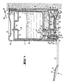
- Fig. 1 zeigt einen handelsüblichen Ausgabebehälter im Schnitt;
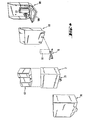
- Fig. 2 diesen Ausgabebehälter als Explosionsschaubild, wobei die Einzelteile perspektivisch dargestellt sind;
- Fig. 3 zeigt den erfindungsgemäßen Ausgabebehälter perspektivisch im Teilschnitt;
- Fig. 4 zeigt als Explosionsschaubild Einzelteile des Ausgabebehälters gemäß Fig. 3;
- Fig. 5 zeigt den Pumperibereich des Ausgabebehälters in perspektivischer Darstellung;
- Fig. 6. zeigt als Detail einen Schnitt des Ausgabebehälters gemäß der Linie VV in Fig. 5;
- Fig. 7 zeigt das Elektronikgehäuse in perspektivischer Darstellung von der Rückseite;
- Fig. 8 das gleiche Gehäuse von der Vorderseite;
- Fig. 9 zeigt den Einschub mit dem Batterieteil;
- Fig. lo zeigt die Innenansicht des Elektronikgehäuses mit Sensorplatte und Abschirmelektrode bei im Gehäuse angeordneten Elektromagneten;
- Fig. 11 den zugehörigen Einschub;
- Fig. 12 ein Elektronikgehäuse ohne Einbauten mit Rastenfenster;
- Fig. 13 den zugehörigen Einschub mit Rasten, eingebauten Elektromagnet und Platine;
- Fig. 14 zeigt das Schaltbild der Platine.
- Die Wandbefestigung 1 besteht aus einer ebenen Platte, die die Rückwand 7 bildet und Bohrungen 8 aufnimmt, die zum Verschrauben der Wandbefestigung 1 an eine Raumwand dienen. Die Bohrungen 8 sind ausgesenkt, so daß Senkschrauben eingesetzt werden können. Die Rückwand 7 wird rechts und links von Seitenwänden 59 begrenzt, die eine dreieckige Form aufweisen und im unteren Bereich abgewinkelt sind. Zwischen den abgewinkelten Enden der Seitenwände.59 erstreckt sich eine rinnenförmige Halterung 6, die direkt an der Rückwand 7 angebracht ist und ebenso wie die Führung 3,. die Feder 4 und der hakenförmige Ansatz 5 zur Aufnahme, bzw. Befestigung des Ausgabebehälters 2 dient.
- Die Führung 3 weist die Form einer Lasche auf, die um dieWandstärke derRückwand 7 versetzt nach innen an derRückwand 7 angeordnet ist. In ihrem oberen Bereich ist .sie durch rechts und links angeordnete Freiräume 60 von der Rückwand 7 getrennt, so daß die Brücke 11, in der die Führungsnut lo des Ausgabebehälters 2 entlang seiner Rückwand 9.endet, die Führung 3 umgreift. Die Feder 4 trägt an.ihrem oberen Ende einen hakenförmigen Ansatz 5 und ist integrales Teil der Führung 3. Sie greift beim Einsetzen des Ausgabebehälters 2 in den im Vorderteil der Brücke 11 befindlichen Halteschlitz 12 ein, wodurch der Ausgabebehälter.2 in der Wandbefestigung arretiert ist.
- Der Ausgebebehälter 2 weist an seinem Boden 13 ein U-förmiges Profil 14 auf. Der Steg 16 des U-förmigen Profils 14 erstreckt sich parallel zur Behälterrückwand 9 und wird durch die rinnenförmige Halterung 6 der Wandbefestigung 1 aufgenommen. Die rechts und links des.Steges 16 angeordneten Schenkel 15 des U-förmigen Profils 14 weisen ein dreieckiges Profil auf, d.h. sie verjüngen sich von der Behälterrückwand 9 zur Behältervorderwand 61 und weisen in der nach unten.zeigenden Spitze des Dreiecks je eine Lagerbohrung 17 auf, während sich parallel zum Boden 13 je ein Langloch 18 erstreckt.
- Unter dem Boden 13 des Ausgabebehälters 2 ist ein Modul 21 angeordnet, der den Behälterboden 13 teilweise durchdringt und in den Behälterinnenraum 25 hineinragt. Unterhalb des Einlaßventiles 22 ist der Modul 21 als Ringansatz ausgebildet und formt hier den Körper der Pumpe 29, d.h. einen rohrförmigen Stutzen, der von der Pumpenmembran 56 abgeschlossen wird. Die Pumpenmembran 56 weist Topfform auf. Ihr mittleres Bodenstück ist verstärkt ausgeführt, der den zylindrischen Teil der Pumpe 29 umgreifende Rand wird durch einen Haltefederring 55 mit dem Modul 21 verbunden.
- Von der Pumpe 29 erstreckt sich ein Pumpkanal 3o in Richtung des Auslaßventils 31. Mit diesem Pumpkanal 3o ist ein Entlastungskanal 23 verbunden, der in eine Öffnung 28 mündet, die.sich in einem Dorn 27 unterhalb des Messers 26 befindet. Im Betriebszustand des Seifenspenders ist die öffnung 28 durch den Halsansatz 50 des Vorratsbehälters 49 abgedeckt, so daß bei Betätigung der Pumpe 29 die flüssige Seife nicht in den Behälterinnenraum 25 zurückgedrückt wird, sondern über den Pumpkanal 3o das Auslaßventil 31 erreicht.
- Der beim Pumpvorgang auftretende Druck schließt das Einlaßventil 22 und hebt durch Druck auf den Druckflansch 36 des Ventilkörpers 32 diesen gegen die Wirkungsrichtung der Druckfeder 62 an, wordurch die Ventilkörperspitze 33 die Düsenbohrung 35 in der Ventil- kappe 34 freigibt, so daß die Seife aus der Düsenbohrung 35 austreten kann. Um zu vermeiden, daß z.B. durch Temperaturänderungen, der Druck im Pumpkanal 3o ansteigt und das Ventil leck wird, ist eine Ausgleichsbohrung 24 vorgesehen.
- Die Betätigung der Pumpenmembran 56 erfolgt über einen Betätigungshebel 19. Der Betätigungshebel 19 besteht aus einem Griff 37 und einer Abdeckplatte 38, die den gesamten Bodenbereich des Seifenspenders verschließt und so ein Verschmutzen der Pumpe 29 und des Auslaßventils 31 von außen verhindert. Auf der Abdeckplatte 38 ist ein Druckpolster 40 angeordnet, das aus einem zylindrischen Aufsatz mit abgeflachtem kugeligen Ansatz besteht. Dieses Druckpolster 4o greift bei der Bewegung des Griffes 37 an der Pumpenmembran 56.an und drückt diese in den Modul 21 ein, wodurch die dort befindliche Seife über das Auslaßventil 31 ausströmt.
- Eine im vorderen Bereich der Abdeckplatte 38 angeordnete Anschlagschraube 41 dient zur Begrenzung der Bewegung des Griffes 37 und damit zur Regulierung der Eindringtiefe des Druckpolsters 4o in die Pumpenmem- .bran 56. Durch diese Regulierung wird die auszugebende Seifenmenge eingestellt. Die Anschlagschraube 41 ist dabei normalerweise als Madenschraube ausgeführt, die selbsthemmend in der Abdeckplatte 38 angeordnet ist.
- Die Lagerung des Griffes 37 erfolgt über Gelenkhebel 39, die federnd mit dem Griff 37 verbunden sind. Sie tragen an ihren Enden nach außen gerichtete Achsstummel 54, die in die Lagerbohrungen 17 des U-förmigen Profils 14 eingreifen.
- Bei Einsatz des Seifenspenders in desinfizierten Räumen ist es erforderlich, daß der Bedienende, beispielsweise ein Chirurg, mit sterilen Händen arbeitet und nicht mit den Händen den Griff 37 des Seifenspenders berührt. Die Betätigung des Seifenspenders soll mit dem Arm erfolgen, wozu der Betätigungshebel 19 durch Distanzstücke 42 so verlängert wird, daß die Distanzstücke 42 den Griff 37 mit der Abdeckplatte 38 und dem Gelenkhebel 39 verbinden. Die Abdeckhaübe 2.o ist in ihrem unteren Bereich mit zwei Scharnierarmen 43 versehen, an denen sich Gelenkzapfen 58 befinden. Diese Gelenkzapfen 58 greifen in die Langlöcher 18 des U-förmigen Profils 14 ein, so daß die Abdeckhaube 2o in Richtung auf die Wandbefestigung 1 verschoben werden kann, so daß die Nase 46, die die Ausnehmung 45 in der Abdeckhaube 2o be-. grenzt, hinter die Raste 47 des Ausgabebehälters 2 einrastet.
- Die im Bodenbereich der. Abdeckhaube 2o.befindliche Aussparung 44 bildet eine Öffnung für das Auslaßventil 31, durch die die Seife austritt.
- Die Sichtfenster 48 befinden sich in den Haubenseitenwänden 63 der Abdeckhaube 2o und werden nur einseitig von der Haubenseitenwand 63 begrenzt. Die gegenüberliegende Begrenzung erfolgt durch die Wandbefestigung 1, d.h. deren Seitenwänden 59.
- Der Vorratsbehälter 49 weist quaderförmige Gestalt auf und besitzt an einer Längsseite einen nach außen ragenden Halsansatz 50, der mit einer Folienkappe 51 abgedeckt ist. Der Vorratsbehälterboden 64 weist zwei gegenüberliegende Vertiefungen 52 auf, die in der Mitte einen Steg 53 freilassen. Dieser Steg 53 dient zum Einsetzen des Vorratsbehälters 49 in den Ausgabebehälter 2, wobei die Vertiefungen 52 gestatten, daß der Steg 53 mit den Fingern ergriffen werden kann.
- Das öffnen des Seifenspenders erfolgt vermittels eines Hebels 57, der aus einem, an einem Ende sichelförmig gebogenem Flachmaterial besteht. Das sichelförmig gebogene Stück des Hebels 57 wird dazu in die Ausnehmung 45 eingelegt und der Hebel 57.dann nach oben bewegt. Der Hebel 57 stützt sich dabei an der Wand ab (bei Fig. 3 am Elektronikgehäuse lol) und hebt die Nase 46 der Abdeckhaube 2o aus der Raste 47 des Ausgabebehälters 2 hinaus, so daß die Abdeckhaube 2o in dem Langloch 18 durch die Gelenkzapfen 58 geführt, auf den Bedienenden zubewegt und zur Freigabe des Ausgabebehälters 2 abgeklappt werden kann. In den Ausführungsbeispielen nach Fig. 3-13 ist der Mechanismus der Abdeckhaube ähnlich, wurde aber in der Zeichnung nicht weiter dargestellt.
- Die Fig. 3 zeigt, wie der gleiche Spender durch austauschen des Betätigungshebels 19 in einen elektronisch betätigbaren Spender umrüstbar ist. Der Betätigungshebel 19 ist in diesem Falle als Doppelhebel ausgeführt, also mit zwei Armen ausgerüstet, von denen der eine Arm wie bisher das Druckpolster 4o trägt, das auf die Pumpenmembran 56 einwirkt, wohingegen der zweite Arm durch den Magnetanker 7o des Elektromagneten 65 beaufschlagt wird. Der Elektromagnet 65 ist bei dieser Ausführungsform im rückwärtigen Bereich des Elektronikgehäuses lol fest installiert, neben ihm ist die Platine lo4 angebracht, die die Elektronikaggregate zur Steuerung des Elektromagneten 65 aufnimmt.
- Die Hebelseite des Betätigungshebels 19, die das Druckpolster 4o trägt, weist eine Verlängerung lo5 auf, in deren vorderen Bereich die Rückholfeder 66 angeordnet ist. Diese Rückholfeder 66 hat im wesentlichen die Aufgabe, das Gewicht des Magnetankers 7o auszugleichen und dadurch die Pumpenmembran 56 weitgehend zu entlasten.
- Da alle elektrischen Komponenten nach Möglichkeit völlig vom Naßteil des Seifenspenders getrennt sein sollten, sind sie, wie die Figuren 7 und 8 zeigen, geka-pselt. In einfachster Form kann das dadurch geschehen, daß das Elektronikgehäuse löl zur Vorderseite hin geschlossen ist und nur einen Durchbruch lo6 aufweist, über.dem sich der Elektromagnet 65 befindet und in den der Betätigungshebel 19 eingreift. Bei dieser Ausführungsform ist, wie Fig. 7 zeigt, der Elektromagnet 65 von der Rückseite lo7 des Elektronikgehäuses lol zugänglich, ebenso wie die Platine lo4 und der Änschießkondensator 98.
- Die Sensorplatte 71 ist am Boden der Tasche lo8 des Elektronikgehäuses lol angeordnet Über ihr befindet sich die Abschirmelektrode 69, die die Sensorplatte 71 vor der Beeinflussung durch den Füllstand der Seife im Vorratsbehälter 49 abschirmt. Nicht dargestellte Schrauben werden.durch die Befestigungsbohrungen lo9 geführt und dienen zur Befestigung des Elektronikgehäuses lol an einer Hauswand o.ä.
- Die Tasche lo8 ist in ihrem unteren Bereich mit einer leitfähigen Schicht llo versehen, die eine Beeinträchtigung der Seifenausgabe aus der Ausgabevorrichtung durch Verschmutzen der Taschenunterseite verhindert.
- Der Einschub 68, der senkrecht von oben in das Elektronikgehäuse 101 eingeschoben wird, enthält die Stromquelle, also die elektrochemischen Elemente 72. In Fig. 9 sind diese elektrochemischen Elemente als Monozellen dargestellt, stattdessen können aber auch wiederaufladbare Akkumulatoren eingesetzt werden. Über die Kontaktfedern 111 wird der Einschub 68 elektrisch mit dem Elektronikgehäuse lol verbunden, das ebenso,wie Fig.lo zeigt, Kontaktfedern 111 aufweist. Zwischen den einzelnen Kontaktfedern 111 herrscht unterschiedliche Spannung, da der Elektromagnet 65 mit voller Spannung betrieben werden muß, um die erforderliche Leistung zu erbringen, der Näherungsschalter 67 als solcher aber mit einer geringeren Spannung betrieben werden kann, wodurch Strom eingespart wird. Der Näherungsschalter 67 setzt sich dabei aus der Platine lo4, dem Anschießkondensator 98, sowie der Sensorplatte.71 zusammen, die gemäß Fig. lo im Elektronikgehäuse lol untergebracht sind.
- Eine Einstellschraube 112 aus isolierendem Material ermöglicht durch Verstellen der Höhe der Abschirmelektrode 69 in der Tasche lo8 ein Einstellen der Ansprechentfernung, d.h. der Entfernung, bei der der Spender bei Annäherung der Hand unter den Spender, also in den Bereich der Sensorplatte 71, Seife ausgibt.
- Aufnahmebohrungen 113 dienen dem Verschrauben des Ausgabebehälters 2 mit dem Elektronikgehäuse lol. Sie sind in Ansätzen 114 angeordnet, die Teil der Rückseite lo7 des Elektronikgehäuses sind.
- In Fig. 7 und Fig. 8 waren, wie dargestellt die elektrischen Teile dadurch gekapselt, daß sie vom Elektronikgehäuse lol nach vorne, also zur Seifenspenderseite umschlossen waren, so daß sie nur von der Wandseite erreicht werden konnten. Die Fig. lo zeigt hier die alternative Lösung, d.h., alle elektrischen Teile sind auf der Rückseite lo7 des Elektronikgehäuses lol angeordnet und somit von vorne offen zugängig. Die Abdeckung gegenüber dem Seifenspender erfolgt durch den Einschub 68, wie er in der Fig. 11 dargestellt ist, und dessen Vorderseite 115 bis auf den Durchbruch lo6, durch den der Betätigungshebel 19 . am Elektromagneten 65 angreift und die Langlöcher 116 völlig geschlossen ist.
- Die Figuren 12 und 13 zeigen eine weitere Paarung. von Elektronikgehäuse lol und Einschub 68, wobei hier der Einschub 68 alle die elektrischen, bzw. elektronischen Teile aufnimmt, die einer Wartung bedürfen. Das sind zum einen die elektrochemischen Elemente 72, die nachgeladen oder ersetzt werden müssen, zum anderen die Platine lo4, die ggf. überprüft werden muß, des weiteren der.Elektromagnet 65 und der Anschießkondensator 98. Da der Elektromagnet 65 gegenüber.dem Betätigungshebel 19 stets eine feste, sich nicht verändernde Position einnehmen muß, wenn eine gleiche Ausgabemenge durch die Pumpbewegung bewerkstelligt werden soll, ist der Einschub 68 in seiner Lage arretiert. Die Arretierung erfolgt im rechten und linken flügel 117 des Elektronikgehäuses lol.durch das Einbringen von Rastenfenstern lo3 und durch an den Einschubseitenwänden 118 angeordnete federnde Lappen 119, die aus der Einschubseitenwand 118 nach außen heraus federn und so in die Rastenfenster lo3 des Elektronikgehäuses lol eingreifen. Beim Einsetzen des Einschubs 68 in das Elektronengehäuse lol werden diese federnde Lappen 119 nach innen gedrückt und treten erst am Rastenfenster 103 wieder nach außen, wo sie den Einschub 68 in der vorgesehenen Position arretieren. Bei dieser, in Fig. 12 dargestellten Ausführungsform weist das Elektronikgehäuse lol nur noch im Bereich der Tasche lo8 Teile auf, die mit dem Näherungsschalter 67 über den Abschirmkontakt 12o und den Sensorkontakt 121 verbunden sind.
- Fig. 14 zeigt den Schaltplan des Näherungsschalters 67, also im wesentlichen die Verdrahtung der Aggregate, die auf der Platine lo4 angeordnet sind. Die Sensorplatte 71 ist über einen Festkondensator 76, der zur Abtrennung der Gleichspannung dient, mit dem variablen Oszillator 79 verbunden. Dieser variable Oszillator 79 ist als rückgekoppelter NAND-Schmitt-Trigger ausgeführt. Der Widerstand 78 dient als Rückkopplungswiderstand und gleichzeitig zur Einstellung der Frequenz. Desweiteren wird die Frequenz über den Frequenzeinstellkondensator 73 eingestellt. Analog erfolgt die Frequenzeinstellung.des Festoszillators 80 durch den Festkondensator 75 zur Bereichsbegrenzung des Festöszillators 80 und den Trimmerkondensator 74. Ein Widerstand 77 dient zur Ableitung der statischen Aufladung der Sensorelektrode.
- Als elektrochemisches Element 72 sind fünf Monozellen zu jeweils 1,5 Volt Spannung eingesetzt, so daß das gesamte elektrochemische Element 72 eine Betriebsspannung von 7,5 Volt aufweist. Zur Speisung des IC wird hinter der dritten Zelle die Spannung abgezweigt und über die Speisediode 97 dem IC-Parallelkondensator 96 zugeführt, der mit dem positiven Speisepunkt 122 des IC verbunden ist. Die Ausgänge der beiden Oszillatoren 79, 80 sind mit den beiden Eingängen des dritten NAND-Schmitt-Triggers verbunden, der als Phasendiskriminator 81 geschaltet ist. Über den .Siebwiderstand 82 führt die entstandene Niederfrequenzspannung und den Siebkondensator 83,zur Abtrennung von Hochfrequenzresten wird der Trennkondensator 84 beaufschlagt, hinter dem die Kurzschlußdiode 86 für die negative Halbwelle und die Gleichrichterdiode 85 für den NAND-Schmitt-Trigger 88'angeordnet ist. Der NAND-Schmitt-Trigger 88 ist über den Arbeitswiderstand 89 mit Masse verbunden und weist ebenfalls einen Anschluß zu Meßpunkt M auf, der zum Einpegeln des Gerätes dient. Ein Ladekondensator 87 ist parallel zur Kurzschlußdiode 86 geschaltet und vor dem NAND-Schmitt-Trigger 88 angeordnet, dem der Ladewiderstand 9o und der Differenzierkondensator 91 nachgeschaltet. sind. Der Differenzierkondensator 91 ist mit dem Entladewiderstand 92 und dem Rückkopplungskondensator 93 verbunden, der über den Treibertransistor 99 und den Leistungstransistor loo den Elektromagneten 65 beaufschlagt. Parallel zu diesem ist die Diode 95 zum Kurzschließen von Spannungsspitzen beim Abschalten geschaltet. Der Anschießkondensator 98 ist parallel zum elektrochemischen Element 72 angeordnet, so daß der Elektromagnet 65 stets mit der Vollspannung versorgt wird, wenn der Leistungstransistor loo anspricht. Die Basis des Leistungstransistors loo und der Treibertransistor 99 sind dabei über einen Emitterwiderstand 94 mit Masse verbunden.
Claims (18)
Priority Applications (1)
| Application Number | Priority Date | Filing Date | Title |
|---|---|---|---|
| AT83108248T ATE23431T1 (de) | 1982-08-26 | 1983-08-22 | Elektrisch betaetigbare ausgabevorrichtung. |
Applications Claiming Priority (2)
| Application Number | Priority Date | Filing Date | Title |
|---|---|---|---|
| DE3231806A DE3231806C2 (de) | 1982-08-26 | 1982-08-26 | Elektrisch betätigbare Ausgabevorrichtung |
| DE3231806 | 1982-08-26 |
Publications (3)
| Publication Number | Publication Date |
|---|---|
| EP0104422A2 true EP0104422A2 (de) | 1984-04-04 |
| EP0104422A3 EP0104422A3 (en) | 1985-01-16 |
| EP0104422B1 EP0104422B1 (de) | 1986-11-12 |
Family
ID=6171783
Family Applications (1)
| Application Number | Title | Priority Date | Filing Date |
|---|---|---|---|
| EP83108248A Expired EP0104422B1 (de) | 1982-08-26 | 1983-08-22 | Elektrisch betätigbare Ausgabevorrichtung |
Country Status (3)
| Country | Link |
|---|---|
| EP (1) | EP0104422B1 (de) |
| AT (1) | ATE23431T1 (de) |
| DE (2) | DE3231806C2 (de) |
Families Citing this family (4)
| Publication number | Priority date | Publication date | Assignee | Title |
|---|---|---|---|---|
| US4722372A (en) * | 1985-08-02 | 1988-02-02 | Louis Hoffman Associates Inc. | Electrically operated dispensing apparatus and disposable container useable therewith |
| US4989755A (en) * | 1988-12-20 | 1991-02-05 | Shiau Guey Chuan | Automatic cleaning-liquid dispensing device |
| DE3902476A1 (de) * | 1989-01-27 | 1990-08-02 | Feldmuehle Ag | Ausgabevorrichtung fuer fluessige oder pastoese gueter |
| DE102007060130A1 (de) * | 2007-12-15 | 2009-06-18 | Venoplas Ag | Flüssigkeitsspender |
Family Cites Families (8)
| Publication number | Priority date | Publication date | Assignee | Title |
|---|---|---|---|---|
| US3327901A (en) * | 1963-12-13 | 1967-06-27 | Jet Dispenser Corp | Dispenser |
| US3273752A (en) * | 1965-02-11 | 1966-09-20 | Geza E Horeczky | Photo-electric controlled dispenser |
| US3434628A (en) * | 1967-01-23 | 1969-03-25 | Bernard A Ceraldi | Automatic soap dispenser |
| FR2263643A1 (en) * | 1974-03-05 | 1975-10-03 | Faeam | Capacitive proximity alarm - uses capacitor between ground and amplifier input point |
| IT1006432B (it) * | 1974-04-12 | 1976-09-30 | Bassani Spa | Mezzi di installazione e prote zione particolarmente per inter ruttori di prossimita o simili |
| GB2054151A (en) * | 1979-07-06 | 1981-02-11 | Watford Electric Co Ltd | Proximity Switch |
| US4316555A (en) * | 1980-03-03 | 1982-02-23 | Steiner Corporation | System for dispensing fluids |
| DE3036523C2 (de) * | 1980-09-27 | 1983-03-24 | Feldmühle AG, 4000 Düsseldorf | Ausgabevorrichtung für flüssige oder pastöse Güter |
-
1982
- 1982-08-26 DE DE3231806A patent/DE3231806C2/de not_active Expired
-
1983
- 1983-08-22 DE DE8383108248T patent/DE3367509D1/de not_active Expired
- 1983-08-22 EP EP83108248A patent/EP0104422B1/de not_active Expired
- 1983-08-22 AT AT83108248T patent/ATE23431T1/de not_active IP Right Cessation
Also Published As
| Publication number | Publication date |
|---|---|
| EP0104422B1 (de) | 1986-11-12 |
| DE3367509D1 (en) | 1987-01-02 |
| DE3231806A1 (de) | 1984-03-01 |
| EP0104422A3 (en) | 1985-01-16 |
| ATE23431T1 (de) | 1986-11-15 |
| DE3231806C2 (de) | 1984-06-14 |
Similar Documents
| Publication | Publication Date | Title |
|---|---|---|
| EP0455679B1 (de) | Ausgabevorrichtung für flüssige oder pastöse güter | |
| AT508223B1 (de) | Sanitärspender mit kapazitivem sensor | |
| DE60317072T2 (de) | Verdampfer | |
| EP0139964B1 (de) | Vorrichtung zur Dosierung von Kaffeepulver an einer Kaffeemaschine | |
| EP0777077A1 (de) | Schmierstoffspender mit elektromotorisch gesteuerter Abgabe eines Schmierstoffes an eine Maschine | |
| DE60213491T3 (de) | Spender mit Erdungsvorrichtung und Verfahren dafür | |
| EP0103765B1 (de) | Elektrisch betätigbare Ausgabevorrichtung | |
| EP0104422B1 (de) | Elektrisch betätigbare Ausgabevorrichtung | |
| EP0419613B1 (de) | Gerät zur pflege von kontaktlinsen | |
| DE3400575A1 (de) | Durch gleichspannung mittels eines kapazitiven naeherungsschalters betaetigbare ausgabevorrichtung | |
| DE102011051612B4 (de) | Waage | |
| DE3249421A1 (de) | Elektrisch betaetigbare ausgabevorrichtung | |
| DE8810834U1 (de) | Aufputz-Gehäuse für Spülarmaturen | |
| DE4211494A1 (de) | Dispenser, insbesondere für Flüssigseife | |
| DE3036523C2 (de) | Ausgabevorrichtung für flüssige oder pastöse Güter | |
| DE2539746C3 (de) | Regelgerät | |
| DE2401097A1 (de) | Steuerschaltung zur betaetigung durch eine mit ihr koppelbare betaetigungsschaltung | |
| DE8333614U1 (de) | Vorrichtung zur dosierten abgabe von fluessigkeit | |
| DE69209150T2 (de) | Flüssigseifenspender | |
| DE202009014107U1 (de) | Druckmechanismus eines Seifenspenders mit der Möglichkeit zur Einstellung der Dosiermenge der flüssigen Seife | |
| DE3745023C1 (de) | Abfalleimer | |
| DE2850862C2 (de) | Vorrichtung zum Duschen von Vögeln | |
| DE10313359A1 (de) | Schaltervorrichtung | |
| DE202025108007U1 (de) | Haustier-Trinkwasserspender mit Halterung | |
| DE9407242U1 (de) | Toilettenpapier-Befeuchter |
Legal Events
| Date | Code | Title | Description |
|---|---|---|---|
| PUAI | Public reference made under article 153(3) epc to a published international application that has entered the european phase |
Free format text: ORIGINAL CODE: 0009012 |
|
| 17P | Request for examination filed |
Effective date: 19830909 |
|
| AK | Designated contracting states |
Designated state(s): AT BE CH DE FR GB IT LI LU NL SE |
|
| PUAL | Search report despatched |
Free format text: ORIGINAL CODE: 0009013 |
|
| AK | Designated contracting states |
Designated state(s): AT BE CH DE FR GB IT LI LU NL SE |
|
| 17Q | First examination report despatched |
Effective date: 19860416 |
|
| GRAA | (expected) grant |
Free format text: ORIGINAL CODE: 0009210 |
|
| ITF | It: translation for a ep patent filed | ||
| AK | Designated contracting states |
Kind code of ref document: B1 Designated state(s): AT BE CH DE FR GB IT LI LU NL SE |
|
| REF | Corresponds to: |
Ref document number: 23431 Country of ref document: AT Date of ref document: 19861115 Kind code of ref document: T |
|
| REF | Corresponds to: |
Ref document number: 3367509 Country of ref document: DE Date of ref document: 19870102 |
|
| ET | Fr: translation filed | ||
| PLBE | No opposition filed within time limit |
Free format text: ORIGINAL CODE: 0009261 |
|
| STAA | Information on the status of an ep patent application or granted ep patent |
Free format text: STATUS: NO OPPOSITION FILED WITHIN TIME LIMIT |
|
| 26N | No opposition filed | ||
| ITPR | It: changes in ownership of a european patent |
Owner name: CESSIONE;SCOTT FELDMUEHLE GMBH |
|
| REG | Reference to a national code |
Ref country code: CH Ref legal event code: PUE Owner name: SCOTT-FELDMUEHLE GMBH |
|
| ITTA | It: last paid annual fee | ||
| NLS | Nl: assignments of ep-patents |
Owner name: SCOTT-FELDMUEHLE GMBH TE DUESSELDORF, BONDSREPUBLI |
|
| REG | Reference to a national code |
Ref country code: FR Ref legal event code: TP |
|
| REG | Reference to a national code |
Ref country code: GB Ref legal event code: 732 |
|
| PGFP | Annual fee paid to national office [announced via postgrant information from national office to epo] |
Ref country code: GB Payment date: 19930616 Year of fee payment: 11 Ref country code: FR Payment date: 19930616 Year of fee payment: 11 |
|
| PGFP | Annual fee paid to national office [announced via postgrant information from national office to epo] |
Ref country code: SE Payment date: 19930621 Year of fee payment: 11 Ref country code: LU Payment date: 19930621 Year of fee payment: 11 Ref country code: AT Payment date: 19930621 Year of fee payment: 11 |
|
| PGFP | Annual fee paid to national office [announced via postgrant information from national office to epo] |
Ref country code: BE Payment date: 19930705 Year of fee payment: 11 |
|
| PGFP | Annual fee paid to national office [announced via postgrant information from national office to epo] |
Ref country code: CH Payment date: 19930715 Year of fee payment: 11 |
|
| PGFP | Annual fee paid to national office [announced via postgrant information from national office to epo] |
Ref country code: DE Payment date: 19930825 Year of fee payment: 11 |
|
| PGFP | Annual fee paid to national office [announced via postgrant information from national office to epo] |
Ref country code: NL Payment date: 19930831 Year of fee payment: 11 |
|
| EPTA | Lu: last paid annual fee | ||
| PG25 | Lapsed in a contracting state [announced via postgrant information from national office to epo] |
Ref country code: LU Free format text: LAPSE BECAUSE OF NON-PAYMENT OF DUE FEES Effective date: 19940822 Ref country code: GB Effective date: 19940822 Ref country code: AT Effective date: 19940822 |
|
| PG25 | Lapsed in a contracting state [announced via postgrant information from national office to epo] |
Ref country code: SE Effective date: 19940823 |
|
| PG25 | Lapsed in a contracting state [announced via postgrant information from national office to epo] |
Ref country code: LI Effective date: 19940831 Ref country code: CH Effective date: 19940831 Ref country code: BE Effective date: 19940831 |
|
| EAL | Se: european patent in force in sweden |
Ref document number: 83108248.2 |
|
| BERE | Be: lapsed |
Owner name: SCOTT-FELDMUHLE G.M.B.H. Effective date: 19940831 |
|
| PG25 | Lapsed in a contracting state [announced via postgrant information from national office to epo] |
Ref country code: NL Effective date: 19950301 |
|
| NLV4 | Nl: lapsed or anulled due to non-payment of the annual fee | ||
| GBPC | Gb: european patent ceased through non-payment of renewal fee |
Effective date: 19940822 |
|
| PG25 | Lapsed in a contracting state [announced via postgrant information from national office to epo] |
Ref country code: FR Effective date: 19950428 |
|
| REG | Reference to a national code |
Ref country code: CH Ref legal event code: PL |
|
| PG25 | Lapsed in a contracting state [announced via postgrant information from national office to epo] |
Ref country code: DE Effective date: 19950503 |
|
| EUG | Se: european patent has lapsed |
Ref document number: 83108248.2 |
|
| REG | Reference to a national code |
Ref country code: FR Ref legal event code: ST |