EP0104458A2 - Tamis pour centrifuge et procédé de fabrication dudit tamis - Google Patents
Tamis pour centrifuge et procédé de fabrication dudit tamis Download PDFInfo
- Publication number
- EP0104458A2 EP0104458A2 EP83108449A EP83108449A EP0104458A2 EP 0104458 A2 EP0104458 A2 EP 0104458A2 EP 83108449 A EP83108449 A EP 83108449A EP 83108449 A EP83108449 A EP 83108449A EP 0104458 A2 EP0104458 A2 EP 0104458A2
- Authority
- EP
- European Patent Office
- Prior art keywords
- sieve
- support structure
- slots
- grooves
- bars
- Prior art date
- Legal status (The legal status is an assumption and is not a legal conclusion. Google has not performed a legal analysis and makes no representation as to the accuracy of the status listed.)
- Granted
Links
Images
Classifications
-
- B—PERFORMING OPERATIONS; TRANSPORTING
- B04—CENTRIFUGAL APPARATUS OR MACHINES FOR CARRYING-OUT PHYSICAL OR CHEMICAL PROCESSES
- B04B—CENTRIFUGES
- B04B7/00—Elements of centrifuges
- B04B7/08—Rotary bowls
- B04B7/12—Inserts, e.g. armouring plates
- B04B7/16—Sieves or filters
Definitions
- the invention relates to a centrifuge sieve with a supporting structure provided on the inside of a centrifugal drum, which carries sieve bars made of wear-resistant material running in the axial direction of the centrifugal drum, and a method for its production.
- the invention has for its object to avoid the above-mentioned disadvantages of the prior art, and in particular to create a centrifuge sieve in which the sieve rods permanently, temperature and corrosion resistant, movable in a defined manner against the supporting structure and connected to it and easy to assemble are, the sieve rods are easily exchangeable without the operation and shape of the centrifuge being restricted.
- a centrifuge sieve should also be easy and inexpensive to manufacture in mass production.
- this object is achieved in that either the sieve bars or the support structure have webs which engage in grooves or slots of the same shape in the other part, so that the sieve bars can only be moved in the axial direction with respect to the support structure.
- Such a support structure can be produced in a particularly advantageous manner by milling oblique slots with parallel side faces that run into the starting material for the support structure that is curved into a convex surface and that have parallel side faces, in that slots with opposite obliquity with respect to the axis more slots with parallel side surfaces are milled, and that the support structure is then bent into a concave surface corresponding to the inside of the centrifugal drum.
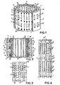
- the centrifuge sieve shown in FIGS. 1, 2 and 3 has a centrifugal drum T with a drum diameter from the decimeter to the meter range, on the inside of which a sieve-like support structure 1 rests, on the inside of which a plurality of, for example made of a hard material or a, is in turn used as wear protection other suitable material Sieve bars 2 with a thickness of a few millimeters and a length of up to approximately 30 cm in the axial direction of the centrifugal drum are fastened at a small lateral distance from one another.
- the support structure 1 is made of a suitable metal, e.g. Steel, and has sieve slots 3 or holes for the passage of the filtrate when centrifuging. Instead, however, the support structure can also consist of a framework of rings which are connected to one another by axially parallel rods, so that the required sieve slots are created between the rods.
- annular webs_4 are provided, on which the supporting structure 1, which may also have annular webs 7 on the outside, possibly rests on spacers 8, a path for the filtrate to pass through the spaces 5 between the sieve bars 2 and the ones below Slots 3 of the support structure 1, the space 9 between the support structure and the drum, and the slots 6 offset from the sieve bar spaces are formed in the drum T. If the slots are not or only slightly offset from one another, the spacers can also be dispensed with.
- the sieve bars 2 can be made of a wear-resistant hard material, for example melt basalt or sintered material, such as sintered ceramic or cemented carbide, for example aluminum oxide or tungsten carbide. If the requirements are somewhat lower, a suitable wear-resistant steel can serve as the material, or a particularly wear-resistant plastic, for example plastic reinforced with glass or carbon fibers, or another suitable material. Since temperature fluctuations of up to 100 ° C can occur during operation of the centrifuge, the materials of the sieve bar, for example tungsten carbide, and the Support structure, for example steel, when fastening the sieve bars 2 to the support structure 1, precautions are taken for a length compensation in order to avoid deformations and breakage of the sieve bars. For this purpose, 2 dovetail-shaped webs 10 are provided on the support surface of the sieve bars, which engage in corresponding, identical grooves or slots 11 in the support structure.
- a wear-resistant hard material for example melt basalt or sintered material, such as sintered ceramic or cemented carbide, for example aluminum oxide
- the described arrangement and guidance of the sieve bars causes the sieve bars 2 to be immovable in the radial direction, but a length compensation is possible in the longitudinal direction, that is to say in the axial direction of the centrifugal drum. Movement in the circumferential direction is made impossible by the axial alignment of the grooves 11.
- FIG. 4 shows another example in which a plurality of layers of sieve bars 2 1 , 2 2 are arranged one behind the other at a small distance in the axial direction, wherein the connection of sieve bars 2 1 , 2 2 and supporting structure 1 again takes place by means of webs and slots 11 1 and 11 2, for example in the form of a dovetail guide. Between the sieve bars 2 1 , 2 2 several rows of sieve slots 3 1 , 3 2 are provided in the support structure 1, through which the filtrate can flow off. In comparison to the first example, the use of several layers of sieve bars allows a longer length of the sieve drum, up to several meters. This is particularly advantageous for sintered materials that only allow a limited rod length.
- the support structure can also consist of several parts arranged one behind the other in the axial direction, each support structure part, for example, carrying only one sieve bar layer, but it is also readily possible to provide several, for example two, layers, the introduction of the sieve bars into the slots can be done from both sides.
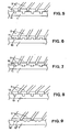
- FIGS. 5-9 show various expedient, geometric shapes of the webs 10 and slots 11.
- the sieve bars 2 have webs 10 with a rectangular cross-section on their support surface 12 on the supporting structure 1 which extend in the axial direction.
- Corresponding slots 11 are provided in the supporting structure 1, into which the webs 10 fit exactly and are possibly clamped.
- the webs 10 can also be provided on the supporting structure 1, while the sieve bars are provided with corresponding slots 11.
- the cross section of the webs 10 and slots 11 according to FIG. 7 is expediently chosen to be trapezoidal, i.e. in the form of a dovetail guide.
- Securing the rods against falling out is also possible with a different geometric shape of the webs, e.g. As shown in FIG. 8, with a rounded shape with a constriction 13 near the support surface 12 and a corresponding design of the slot with an inward expansion.
- a plurality of parallel webs 10 1 , 10 2 can also be provided on the same part, for example on the sieve bars 2 .
- the slots can be designed as deeply limited grooves, as shown in the examples described above, or as deep slots, e.g. the support structure consists of separate bars, which are connected at the ends at most.
- the sieve bars can expand and contract practically unhindered in the direction of the drum axis, but are immovable in the circumferential and radial directions.
- the assembly and replacement of the sieve bars is extremely easy.
- the screen slots 3 and the grooves 11 can indeed be produced in a conventional and known manner, for example using suitable milling tools.
- a milling tool is attached to the same point on the surface, but with an opposite slope to the axis, i.e. with an application direction running on the other side of the same, and an additional slot is milled obliquely to the existing slot, so that a dovetail groove is formed.
- the support structure is then bent in the opposite direction to a concave surface which corresponds to the shape of the inside of the centrifugal drum.
- the dovetail grooves come to rest on the inside of the support structure.
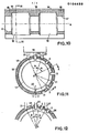
- a tube 14 is used as the starting material, the diameter of which corresponds approximately to the inner diameter of the centrifugal drum and the zones lying one behind the other in the direction of the axis A. has a smaller wall thickness 15 and a larger wall thickness 16, and the zones 16 of greater wall thickness form beads or webs 17 on the inside, while the outside 18 of the tube 14 is smooth and has a uniform diameter.
- the machining is carried out from the outside using a milling tool 19 with three parallel milling cutters 20, 21 and 22, for example with three circular saw blades, or a central circular saw blade 20 and two outer side milling cutters 21 and 22.
- the penetration depth of the central milling cutter 20 is selected or set in this way that this cuts through the entire wall when milling a slot along a surface line of the tube 14, that is to say in the axial direction, in the zones 15 of smaller wall thickness, so that here there is a continuous slot from the outside, a later sieve slot 3, while in the Zones 16 of greater wall thickness only a non-continuous groove is milled, and a continuous ring remains, the later annular web 17.
- the depth of the two outer milling cutters 21 and 22, on the other hand, is selected or set so that during milling the wall of the tube 14 is not completely penetrated in either of the two zones 15 and 16, so that only grooves are formed.
- the three cutters 20, 21 and 22 work simultaneously during the milling process. While the middle milling cutter produces the later screen slots 3, the outer milling cutter 21 mills a groove, the side surfaces of which run obliquely to the axis A. After this operation, the tube is rotated through an angle M 14, which is selected such that the other outer cutter 22 comes to the position where the cutter 21 is already an oblique N ut generated.
- this milling cutter 22 then mills a flank into the groove already pre-milled by the milling cutter 21, which flank also extends obliquely to the axis with opposite inclination, so that a dovetail groove 11 with a trapezoidal cross section is created, at the same time a new slot is milled by the central milling cutter 20, and a new groove is prepared by the milling cutter 21.
- the tube 14 is then rotated again by the angle o (.) And the operations are repeated until the entire surface of the tube 14 is provided with slots 3 and grooves 11.
- the tube 14 is slit open at a point 23 , bent into a concave surface with an opposite curvature, and inserted into the inside of the centrifugal drum, so that the dovetail grooves 11 now come to lie on the inside.
- the insertion of the sieve rods into the dovetail grooves can be done either immediately after the end of the Milling process, or after the support structure has been bent into its final shape, if necessary also only after insertion into the centrifugal drum.
- FIG. 12 demonstrates a method in which the tube 14 is rotated between the work steps by an angle ⁇ , which is selected such that a prepared groove 24 only becomes a finished dovetail groove 25 in the third subsequent work step.
- a centrifuge sieve can be produced in an extremely simple and efficient manner, even in mass production, using the starting material mentioned and the method described.
Landscapes
- Centrifugal Separators (AREA)
- Combined Means For Separation Of Solids (AREA)
Priority Applications (1)
| Application Number | Priority Date | Filing Date | Title |
|---|---|---|---|
| AT83108449T ATE27554T1 (de) | 1982-09-27 | 1983-08-27 | Zentrifugensieb und verfahren zu dessen herstellung. |
Applications Claiming Priority (2)
| Application Number | Priority Date | Filing Date | Title |
|---|---|---|---|
| CH5675/82 | 1982-09-27 | ||
| CH5675/82A CH657287A5 (de) | 1982-09-27 | 1982-09-27 | Zentrifugensieb. |
Publications (3)
| Publication Number | Publication Date |
|---|---|
| EP0104458A2 true EP0104458A2 (fr) | 1984-04-04 |
| EP0104458A3 EP0104458A3 (en) | 1985-05-29 |
| EP0104458B1 EP0104458B1 (fr) | 1987-06-03 |
Family
ID=4297516
Family Applications (1)
| Application Number | Title | Priority Date | Filing Date |
|---|---|---|---|
| EP83108449A Expired EP0104458B1 (fr) | 1982-09-27 | 1983-08-27 | Tamis pour centrifuge et procédé de fabrication dudit tamis |
Country Status (6)
| Country | Link |
|---|---|
| US (1) | US4569761A (fr) |
| EP (1) | EP0104458B1 (fr) |
| JP (1) | JPS59136153A (fr) |
| AT (1) | ATE27554T1 (fr) |
| CH (1) | CH657287A5 (fr) |
| DE (1) | DE3371872D1 (fr) |
Cited By (3)
| Publication number | Priority date | Publication date | Assignee | Title |
|---|---|---|---|---|
| AU666963B2 (en) * | 1992-08-19 | 1996-02-29 | Letella Pty. Ltd. | Screening apparatus |
| DE19502572A1 (de) * | 1995-01-27 | 1996-08-01 | Krauss Maffei Ag | Filterzentrifuge |
| EP1836004A4 (fr) * | 2004-12-23 | 2011-04-27 | Metso Minerals Wear Prot Ab | Barre de charge pour element de criblage ou revetement resistant a l'usure |
Families Citing this family (26)
| Publication number | Priority date | Publication date | Assignee | Title |
|---|---|---|---|---|
| US5165548A (en) * | 1990-04-23 | 1992-11-24 | Hemlock Semiconductor Corporation | Rotary silicon screen |
| US5378364A (en) * | 1992-09-14 | 1995-01-03 | Baker Hughes Incorporated | Conical screen basket centrifuge |
| USRE38494E1 (en) * | 1998-07-13 | 2004-04-13 | Phase Inc. | Method of construction for density screening outer transport walls |
| US6312610B1 (en) * | 1998-07-13 | 2001-11-06 | Phase Inc. | Density screening outer wall transport method for fluid separation devices |
| AU2485600A (en) * | 1999-12-22 | 2001-07-03 | Phase, Inc. | Method of construction for the outer walls of a centrifuge |
| US6915910B2 (en) * | 2001-04-16 | 2005-07-12 | J&L Fiber Services, Inc. | Screen cylinder and method |
| US6755969B2 (en) | 2001-04-25 | 2004-06-29 | Phase Inc. | Centrifuge |
| US6706180B2 (en) * | 2001-08-13 | 2004-03-16 | Phase Inc. | System for vibration in a centrifuge |
| US6805805B2 (en) * | 2001-08-13 | 2004-10-19 | Phase Inc. | System and method for receptacle wall vibration in a centrifuge |
| US20030150782A1 (en) * | 2002-02-14 | 2003-08-14 | Chao-Ho Chen | Screen for paper pulp |
| WO2004080601A2 (fr) * | 2003-03-11 | 2004-09-23 | Phase Inc. | Centrifugeuse a decharge modulable des materiaux denses |
| US6971525B2 (en) * | 2003-06-25 | 2005-12-06 | Phase Inc. | Centrifuge with combinations of multiple features |
| US7371322B2 (en) * | 2003-07-30 | 2008-05-13 | Phase Inc. | Filtration system and dynamic fluid separation method |
| WO2005011833A2 (fr) * | 2003-07-30 | 2005-02-10 | Phase Inc. | Systeme de filtration a nettoyage ameliore et separation de fluide dynamique |
| US7282147B2 (en) * | 2003-10-07 | 2007-10-16 | Phase Inc. | Cleaning hollow core membrane fibers using vibration |
| US10576502B2 (en) | 2012-05-25 | 2020-03-03 | Derrick Corporation | Injection molded screening apparatuses and methods |
| US9409209B2 (en) | 2012-05-25 | 2016-08-09 | Derrick Corporation | Injection molded screening apparatuses and methods |
| US11161150B2 (en) | 2012-05-25 | 2021-11-02 | Derrick Corporation | Injection molded screening apparatuses and methods |
| CA3110031C (fr) | 2012-05-25 | 2023-05-02 | Derrick Corporation | Dispositifs de tamisage moules par injection et procedes |
| EP3441145A4 (fr) * | 2016-04-06 | 2019-12-11 | Tokyo Roki Co., Ltd. | Séparateur d'huile |
| EP3507029A4 (fr) * | 2016-08-30 | 2020-01-15 | Schmacker Investments PTY Ltd | Élément de fil métallique et procédé de fabrication de fil métallique |
| AU2018260541A1 (en) | 2017-04-28 | 2019-11-07 | Derrick Corporation | Thermoplastic compositions, methods, apparatus, and uses |
| US11505638B2 (en) | 2017-04-28 | 2022-11-22 | Derrick Corporation | Thermoplastic compositions, methods, apparatus, and uses |
| CN107020046B (zh) * | 2017-05-15 | 2019-09-06 | 南京工程学院 | 一种适用于离心筛选的固体混料器 |
| AU2018281297B2 (en) | 2017-06-06 | 2021-10-28 | Derrick Corporation | Method and apparatuses for screening |
| US11213857B2 (en) | 2017-06-06 | 2022-01-04 | Derrick Corporation | Method and apparatus for screening |
Family Cites Families (7)
| Publication number | Priority date | Publication date | Assignee | Title |
|---|---|---|---|---|
| US3100746A (en) * | 1960-04-20 | 1963-08-13 | Inland Steel Co | Screening apparatus |
| ZA715725B (en) * | 1970-08-28 | 1972-05-31 | Dunlop Holdings Ltd | Improvements in sieve screens |
| CA979375A (en) * | 1972-06-26 | 1975-12-09 | Delta Precision Casting Co. | Pocket screen assemblies for centrifugal separators and replacements therefor |
| GB1495208A (en) * | 1975-06-20 | 1977-12-14 | Greening & Sons Ltd N | Screening apparatus |
| CH624315A5 (fr) * | 1977-07-22 | 1981-07-31 | Escher Wyss Ag | |
| GB2033242A (en) * | 1978-10-20 | 1980-05-21 | Greening N Ltd | Screening Apparatus |
| CH654759A5 (de) * | 1981-07-24 | 1986-03-14 | Escher Wyss Ag | Zentrifugensieb. |
-
1982
- 1982-09-27 CH CH5675/82A patent/CH657287A5/de not_active IP Right Cessation
-
1983
- 1983-08-27 DE DE8383108449T patent/DE3371872D1/de not_active Expired
- 1983-08-27 EP EP83108449A patent/EP0104458B1/fr not_active Expired
- 1983-08-27 AT AT83108449T patent/ATE27554T1/de not_active IP Right Cessation
- 1983-09-12 US US06/531,027 patent/US4569761A/en not_active Expired - Lifetime
- 1983-09-27 JP JP58177158A patent/JPS59136153A/ja active Granted
Cited By (5)
| Publication number | Priority date | Publication date | Assignee | Title |
|---|---|---|---|---|
| AU666963B2 (en) * | 1992-08-19 | 1996-02-29 | Letella Pty. Ltd. | Screening apparatus |
| DE19502572A1 (de) * | 1995-01-27 | 1996-08-01 | Krauss Maffei Ag | Filterzentrifuge |
| DE19502572C2 (de) * | 1995-01-27 | 1998-02-12 | Krauss Maffei Ag | Filterzentrifuge |
| EP1836004A4 (fr) * | 2004-12-23 | 2011-04-27 | Metso Minerals Wear Prot Ab | Barre de charge pour element de criblage ou revetement resistant a l'usure |
| US8281933B2 (en) | 2004-12-23 | 2012-10-09 | Metso Minerals (Wear Protection) Ab | Rider bar for screening element or wear-resistant lining |
Also Published As
| Publication number | Publication date |
|---|---|
| US4569761A (en) | 1986-02-11 |
| CH657287A5 (de) | 1986-08-29 |
| JPH0355183B2 (fr) | 1991-08-22 |
| DE3371872D1 (en) | 1987-07-09 |
| ATE27554T1 (de) | 1987-06-15 |
| EP0104458B1 (fr) | 1987-06-03 |
| JPS59136153A (ja) | 1984-08-04 |
| EP0104458A3 (en) | 1985-05-29 |
Similar Documents
| Publication | Publication Date | Title |
|---|---|---|
| EP0104458A2 (fr) | Tamis pour centrifuge et procédé de fabrication dudit tamis | |
| EP0316570A2 (fr) | Tambour de tamisage et son procédé de fabrication | |
| DE2345954C2 (de) | Kernreaktor-Brennelement | |
| EP0499154A1 (fr) | Epurateur | |
| EP0837178B1 (fr) | Procédé pour la fabrication de tamis et tamis ainsi obtenu | |
| EP0156762B1 (fr) | Foret à couronne | |
| WO2012117033A1 (fr) | Filière | |
| DE4402843C2 (de) | Innenräumwerkzeug | |
| EP1065548B1 (fr) | Assemblage d'un élément optique et d'une monture | |
| DE102018118959B3 (de) | Trennscheibe | |
| DE102020111782A1 (de) | Trägerbaugruppe, insbesondere Werkzeugträgerbaugruppe und Verfahren zu deren Herstellung | |
| DE10112165B4 (de) | Stabmesserkopf zum Verzahnen | |
| DE4214061A1 (de) | Siebvorrichtung | |
| DE102011116080B3 (de) | Werkzeugsystem zur spanabhebenden Bearbeitung eines Werkstücks | |
| DE19718938C1 (de) | Dentalwerkzeug | |
| DE3113062A1 (de) | "verfahren zum anbringen von bohrungen mit einem vorbestimmten durchmesser in einer anordnung von uebereinander angeordneten platten, umfassend wenigstens eine platte aus glas- oder kohlenstoffasernverstaerktem material und eine alumiumplatte" | |
| DE29723558U1 (de) | Fräswerkzeug | |
| DE9416221U1 (de) | Räumwerkzeug | |
| EP0531879A1 (fr) | Lame de scie à ruban et procédé pour sa fabrication | |
| DE102016114449A1 (de) | Auflösewalze für eine Offenendspinnvorrichtung | |
| DE3445835A1 (de) | Blechplatte | |
| EP3307467B1 (fr) | Perle de coupe pour un câble de sciage | |
| DE1940722A1 (de) | Rotor fuer Duennschichtbehandlungsapparat | |
| DE3738746A1 (de) | Siebkorb und verfahren zu dessen herstellung | |
| DE19531826C2 (de) | Verfahren zur Herstellung von Stahlfasern |
Legal Events
| Date | Code | Title | Description |
|---|---|---|---|
| PUAI | Public reference made under article 153(3) epc to a published international application that has entered the european phase |
Free format text: ORIGINAL CODE: 0009012 |
|
| 17P | Request for examination filed |
Effective date: 19830827 |
|
| AK | Designated contracting states |
Designated state(s): AT BE DE FR GB IT LU NL SE |
|
| PUAL | Search report despatched |
Free format text: ORIGINAL CODE: 0009013 |
|
| AK | Designated contracting states |
Designated state(s): AT BE DE FR GB IT LU NL SE |
|
| 17Q | First examination report despatched |
Effective date: 19860414 |
|
| GRAA | (expected) grant |
Free format text: ORIGINAL CODE: 0009210 |
|
| AK | Designated contracting states |
Kind code of ref document: B1 Designated state(s): AT BE DE FR GB IT LU NL SE |
|
| REF | Corresponds to: |
Ref document number: 27554 Country of ref document: AT Date of ref document: 19870615 Kind code of ref document: T |
|
| REF | Corresponds to: |
Ref document number: 3371872 Country of ref document: DE Date of ref document: 19870709 |
|
| ITF | It: translation for a ep patent filed | ||
| ET | Fr: translation filed | ||
| PLBE | No opposition filed within time limit |
Free format text: ORIGINAL CODE: 0009261 |
|
| STAA | Information on the status of an ep patent application or granted ep patent |
Free format text: STATUS: NO OPPOSITION FILED WITHIN TIME LIMIT |
|
| 26N | No opposition filed | ||
| ITTA | It: last paid annual fee | ||
| EPTA | Lu: last paid annual fee | ||
| EAL | Se: european patent in force in sweden |
Ref document number: 83108449.6 |
|
| PGFP | Annual fee paid to national office [announced via postgrant information from national office to epo] |
Ref country code: NL Payment date: 19970721 Year of fee payment: 15 Ref country code: AT Payment date: 19970721 Year of fee payment: 15 |
|
| PGFP | Annual fee paid to national office [announced via postgrant information from national office to epo] |
Ref country code: SE Payment date: 19970724 Year of fee payment: 15 |
|
| PGFP | Annual fee paid to national office [announced via postgrant information from national office to epo] |
Ref country code: LU Payment date: 19970805 Year of fee payment: 15 |
|
| PG25 | Lapsed in a contracting state [announced via postgrant information from national office to epo] |
Ref country code: LU Free format text: LAPSE BECAUSE OF NON-PAYMENT OF DUE FEES Effective date: 19980827 Ref country code: AT Free format text: LAPSE BECAUSE OF NON-PAYMENT OF DUE FEES Effective date: 19980827 |
|
| PG25 | Lapsed in a contracting state [announced via postgrant information from national office to epo] |
Ref country code: SE Free format text: LAPSE BECAUSE OF NON-PAYMENT OF DUE FEES Effective date: 19980828 |
|
| PG25 | Lapsed in a contracting state [announced via postgrant information from national office to epo] |
Ref country code: NL Free format text: LAPSE BECAUSE OF NON-PAYMENT OF DUE FEES Effective date: 19990301 |
|
| EUG | Se: european patent has lapsed |
Ref document number: 83108449.6 |
|
| NLV4 | Nl: lapsed or anulled due to non-payment of the annual fee |
Effective date: 19990301 |
|
| REG | Reference to a national code |
Ref country code: GB Ref legal event code: IF02 |
|
| PGFP | Annual fee paid to national office [announced via postgrant information from national office to epo] |
Ref country code: BE Payment date: 20020725 Year of fee payment: 20 |
|
| PGFP | Annual fee paid to national office [announced via postgrant information from national office to epo] |
Ref country code: GB Payment date: 20020730 Year of fee payment: 20 |
|
| PGFP | Annual fee paid to national office [announced via postgrant information from national office to epo] |
Ref country code: DE Payment date: 20020809 Year of fee payment: 20 |
|
| PGFP | Annual fee paid to national office [announced via postgrant information from national office to epo] |
Ref country code: FR Payment date: 20020812 Year of fee payment: 20 |
|
| PG25 | Lapsed in a contracting state [announced via postgrant information from national office to epo] |
Ref country code: GB Free format text: LAPSE BECAUSE OF EXPIRATION OF PROTECTION Effective date: 20030826 |
|
| REG | Reference to a national code |
Ref country code: GB Ref legal event code: PE20 |