EP0104504A1 - Dispositif d'étanchéité à double racleur - Google Patents
Dispositif d'étanchéité à double racleur Download PDFInfo
- Publication number
- EP0104504A1 EP0104504A1 EP83108681A EP83108681A EP0104504A1 EP 0104504 A1 EP0104504 A1 EP 0104504A1 EP 83108681 A EP83108681 A EP 83108681A EP 83108681 A EP83108681 A EP 83108681A EP 0104504 A1 EP0104504 A1 EP 0104504A1
- Authority
- EP
- European Patent Office
- Prior art keywords
- pressure
- housing
- chamber
- lip
- channel
- Prior art date
- Legal status (The legal status is an assumption and is not a legal conclusion. Google has not performed a legal analysis and makes no representation as to the accuracy of the status listed.)
- Granted
Links
- 238000007789 sealing Methods 0.000 title claims abstract description 49
- 239000000463 material Substances 0.000 claims description 7
- 230000035515 penetration Effects 0.000 claims description 7
- 230000000903 blocking effect Effects 0.000 claims description 4
- 238000005192 partition Methods 0.000 claims description 3
- 238000009434 installation Methods 0.000 description 6
- 230000002093 peripheral effect Effects 0.000 description 6
- 241000446313 Lamella Species 0.000 description 5
- 230000000694 effects Effects 0.000 description 4
- 239000012528 membrane Substances 0.000 description 3
- 208000027418 Wounds and injury Diseases 0.000 description 1
- 239000006096 absorbing agent Substances 0.000 description 1
- 238000010276 construction Methods 0.000 description 1
- 239000000356 contaminant Substances 0.000 description 1
- 230000036461 convulsion Effects 0.000 description 1
- 230000006378 damage Effects 0.000 description 1
- 239000013013 elastic material Substances 0.000 description 1
- 230000005484 gravity Effects 0.000 description 1
- 208000014674 injury Diseases 0.000 description 1
- 239000007788 liquid Substances 0.000 description 1
- 238000004519 manufacturing process Methods 0.000 description 1
- 230000013011 mating Effects 0.000 description 1
- 239000002184 metal Substances 0.000 description 1
- 230000000149 penetrating effect Effects 0.000 description 1
- 238000004080 punching Methods 0.000 description 1
- 238000007493 shaping process Methods 0.000 description 1
- 230000035939 shock Effects 0.000 description 1
Images
Classifications
-
- F—MECHANICAL ENGINEERING; LIGHTING; HEATING; WEAPONS; BLASTING
- F16—ENGINEERING ELEMENTS AND UNITS; GENERAL MEASURES FOR PRODUCING AND MAINTAINING EFFECTIVE FUNCTIONING OF MACHINES OR INSTALLATIONS; THERMAL INSULATION IN GENERAL
- F16J—PISTONS; CYLINDERS; SEALINGS
- F16J15/00—Sealings
- F16J15/16—Sealings between relatively-moving surfaces
- F16J15/32—Sealings between relatively-moving surfaces with elastic sealings, e.g. O-rings
- F16J15/3204—Sealings between relatively-moving surfaces with elastic sealings, e.g. O-rings with at least one lip
- F16J15/3232—Sealings between relatively-moving surfaces with elastic sealings, e.g. O-rings with at least one lip having two or more lips
-
- F—MECHANICAL ENGINEERING; LIGHTING; HEATING; WEAPONS; BLASTING
- F16—ENGINEERING ELEMENTS AND UNITS; GENERAL MEASURES FOR PRODUCING AND MAINTAINING EFFECTIVE FUNCTIONING OF MACHINES OR INSTALLATIONS; THERMAL INSULATION IN GENERAL
- F16J—PISTONS; CYLINDERS; SEALINGS
- F16J15/00—Sealings
- F16J15/16—Sealings between relatively-moving surfaces
- F16J15/164—Sealings between relatively-moving surfaces the sealing action depending on movements; pressure difference, temperature or presence of leaking fluid
-
- F—MECHANICAL ENGINEERING; LIGHTING; HEATING; WEAPONS; BLASTING
- F16—ENGINEERING ELEMENTS AND UNITS; GENERAL MEASURES FOR PRODUCING AND MAINTAINING EFFECTIVE FUNCTIONING OF MACHINES OR INSTALLATIONS; THERMAL INSULATION IN GENERAL
- F16J—PISTONS; CYLINDERS; SEALINGS
- F16J15/00—Sealings
- F16J15/56—Other sealings for reciprocating rods
Definitions
- the invention relates to a sealing arrangement with a housing separating a high-pressure area from a low-pressure area, with a rod crossing an opening of the housing and reciprocating in its longitudinal direction, with a seal on the high-pressure side sealing the housing opening with respect to the rod, and a low-pressure side thereof Sealing arranged in the housing opening double wiper ring, which, in addition to an outer wiping member directed against the low-pressure side and bearing against the high-pressure side, has an inner lip against the high-pressure side and abutting against the rod surface for wiping off the oil film adhering thereon, one of which between the gasket and the Wiping ring located chamber leading to the low-pressure area, is provided against the penetration of foreign bodies.
- the scraper ring has the task on the one hand of foreign bodies adhering to the rod surface wipe off the inward movement of the rod so that it cannot enter the seal assembly.
- the outer scraper is provided for this.
- the inner wiper lip serves to wipe off at least a part of the oil film adhering to the surface of the rod when it moves outward.
- Such an oil film is namely dragged through the rod surface through the high-pressure side seal even when it functions properly.
- the part of this oil film stripped from the inner lip of the scraper ring collects in the chamber located between the seal and the scraper ring and is generally dragged back again by the high-pressure seal when the rod is pushed inwards.
- the channel formed in the wiper ring comprises an elastic locking member smoothly match at D is present between the chamber and the low pressure region close to an opposite surface and is deformable by pressure prevailing in the chamber pressure to the outside under withdrawal of the mating surface.
- the elastic locking member expediently bears against the counter surface under pressure when the pressure matches.
- the achieved by the invention effect is the one hand, that the structure is considerably simplified, because the D jerk relief duct is formed in the wiper as such, and therefore a special shaping of the housing and special additional parts omitted for protecting a channel formed in the housing.
- the invention achieves that the channel is completely closed when the pressure between the chamber and the low-pressure region is equalized, because the elastic locking member lies tightly against the counter surface. Foreign bodies cannot enter the channel in this state. If an overpressure forms in the chamber, which pushes the elastic blocking member outward to such an extent that it lifts off the counter surface, foreign bodies are prevented from penetrating by the outward discharge current. In a simple way, pressure relief of the chamber is created on the one hand, and excellent protection against the penetration of foreign bodies on the other hand.
- a check valve is achieved in that the passage crossing the sealing ring is provided at its outer mouth with a valve flap, which, however, does not lie tightly or even with pre-tension in the relaxed state, while its other mouth lies in that surface of the sealing ring that is supported in a sealing function on a side surface of the groove receiving the sealing ring, the channel opening being closed off by this side surface. Because of the fundamentally different prerequisites and the different construction, the known piston seal was therefore unable to provide any suggestions for solving the problem on which the invention is based.
- a combined sealing and scraper ring (FR-PS 2 238 389) which, in a shock absorber arrangement, closes an essentially pressure-free compensation chamber between a rod and a first cylinder and a pressure chamber and between the first cylinder and a second cylinder surrounding it. It contains a sealing ring on the inside to close off the pressure chamber; on the outside an outward wiping lip.
- Zri .en the compensation space and the chamber formed between the seal and the wiper lip is a channel which, in a vertical arrangement with an overhead seal arrangement, should make it possible for the sealing ring to move outwards into the chamber between the sealing ring and the exhaust
- the lip of the squeezed medium can flow back under the effect of gravity into the compensation chamber.
- the double wiper in the sealing arrangement according to the invention is generally formed in one piece. However, it can also be composed of several parts, for example an inner and an outer wiper ring part.
- the resilient locking member is formed by the lip designed as a prestressed wiper member of the wiper ring and flows emanating from the chamber, constantly open channel in the space formed between the outer and inner wiper lip L type in clearance. If there is no or only slight overpressure in the chamber compared to the low-pressure area during normal operation, the outer wiper lip rests on the rod. Only if there is an overpressure within the chamber and thus via the connecting channel in the space between the lips, does the outer wiper lip lift off the surface of the rod in order to let out part of the medium for pressure equalization.
- An elastic sealing lip is provided on the surface part of the scraper ring and an open channel leads from the chamber side of the scraper ring: to the inside of this sealing lip.
- the sealing lip normally rests on the installation housing under elastic pretension. If an overpressure occurs on the chamber side, it lifts off the surface of the installation housing for a short time to relieve pressure in order to allow the medium flow required for the relief to pass through.
- the elastic sealing lip is expediently arranged on the low-pressure end of the surface part of the scraper ring which is intended to cooperate with the housing. However, an arrangement in the middle area of the contact surface between the scraper ring and the installation housing should not be excluded.
- a channel is provided in the scraper ring, which leads from the chamber side to the outside of the scraper ring and has a constriction that can be opened elastically by excess pressure on the chamber side. If this is provided on the outside mouth of the channel, there is a simple production possibility in that the channel is shaped or drilled down to a thin end wall and this end wall is then perforated. The perforation can be made by punching in such a way that a very small opening size remains, which is negligible for the penetration of foreign bodies and which can expand elastically with this relaxation current.
- the principle of the elastically opening constriction in the flow path can also be realized according to the invention in that the channel is recessed in the surface part of the scraper ring which is to be cooperated with the housing and contains an elastic lamella which projects towards the housing surface and which, when the pressure is equalized by your contact with the housing surface essentially closes the flow path, but can escape at internal excess pressure in order to let out pressure medium.
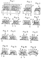
- the rod 1 which reciprocates in the direction of the arrow in FIG. 1 is sealed within the housing 2 by means of a sealing ring 3 against the pressure acting on the pressure side 4 within the housing. Outside the housing, that is to say in region 5, a lower pressure acts, generally atmospheric pressure.
- the scraper ring 6 is arranged, which consists of a relatively hard, sufficiently elastic material which is customary for such purposes. It is located in a housing recess 7 and lies with its outer peripheral surface 9 'on the surface 9 of the housing recess, which for the sake of simplicity is referred to below as the housing surface.
- the housing surface is mostly cylindrical.
- the outer circumferential surface of the scraper ring 6 is also approximately cylindrical, whereby radial projections or lips can be provided for the purpose of better sealing against the housing surface.
- Such an outwardly projecting lip 10 is shown in FIG. 3 on the example of a relaxed scraper ring in comparison to Fig. 2, which shows the same ring in the installed state, recognizable.
- the scraper ring 6 is held within the housing recess 7 by a radially inwardly projecting projection 38.
- this collar can have different radial dimensions in comparison with the radial extension of the scraper ring, as is evident, for example, from ISO 6195.
- the collar can be dispensed with if the wiper ring provided with a metal insert or made of very hard material is pressed into the housing surface 9 with an oversize.
- the wiper ring On the side facing the rod 1, the wiper ring is equipped with an inner wiper lip 11 and an outer wiper lip 12.
- the inner wiper lip 11 serves to retain the liquid film adhering to the rod during the outward stroke.
- the wiper lip 12 serves to wipe off the foreign bodies adhering to the rod during the inward stroke.
- the use of the term "lip" in this context does not mean that the lip shape in the cross-sectional design must be pronounced in all cases. Rather, it depends solely on the described function of the corresponding cross-sectional parts of the wiper ring.
- a constantly open channel 14 leads from the rear surface of the scraper ring, which is connected to the chamber 13, to the lip space 15 thereof.
- the pressure in the chamber 13 therefore also prevails in the lip space 15.
- This pressure increases to a certain extent on, the outer wiper lip 12 is lifted off the counter-sealing surface so that the excess pressure can escape.
- the lip acts in the manner of a check valve, so that no medium and no foreign objects can penetrate into the space between the lips.
- the rear end of the channel 14 lies radially inside a rear support projection 16 of the wiper ring, the channel 14 'in the embodiment according to FIG. 4 opens radially outside the corresponding projection 16'.
- the function of the embodiment according to FIG. 4 is the same as that of the embodiment according to FIG. 2. The function is also not disturbed by the fact that under certain circumstances the projection 16 ′ can rest against the rear surface of the housing recess, because this is only possible then .is when there is no substantial pressure in the chamber 13.
- the embodiment according to FIG. 6 also makes use of the check valve function of an elastic lip.
- the scraper ring which corresponds in its basic form to that shown in FIG. 1, lies with an elastically prestressed lip 17 on the inner surface of the housing projection 8.
- a groove 18 is cut into the circumferential surface of the scraper ring lying against the housing surface in such a way that the pressure prevailing in the chamber 13 can spread right up to the elastic lip 17.
- the lip 17 lifts off from its counter surface and thus allows the chamber 13 to relax.
- the lip is only lifted when there is a flow from the inside to the outside, so that penetration of foreign bodies from the outside in is reliable is excluded.
- a groove 20 is cut, which leads from the rear surface of the scraper ring adjoining the chamber 13 to the front end of the housing recess. There, a lip 21 engages radially outwards over the face 22 of the housing and bears against this under pretension.
- a part 23 of the metallic insert ring 19 projecting beyond the rear surface of the scraper ring serves to position the scraper ring as a stop which interacts with the rear surface of the housing recess and is perforated in places to allow the passage of the medium to the channel 20.
- the lip 21 is functionally similar to the lip 17 of the previously described embodiment.
- FIGS. 8 and 9 act according to another principle.
- An axially parallel bore can be seen therein, which leads from the rear surface of the scraper ring in connection with the chamber 13 to close to its end surface and is separated from it by a thin material wall.
- This material wall 25 is approximately planar in FIG. 8. It can be punched with a stamp of small diameter to form an opening, the diameter of which is so small that no harmful contaminants can penetrate, and which can be elastically expanded due to the elasticity of the material if the strength of the equalizing current should require it. Instead, the membrane can also be pierced without removing material, so that the surfaces delimiting the opening then join again and form a seal against external foreign bodies, while they can yield to internal overpressure.
- the scraper ring according to FIG. 10 has a basic shape which is the same as that of the scraper ring according to FIG. At least one starting point is a groove made up of sections 27 and 28, which runs through from the rear surface of the scraper ring to its end face and is only interrupted at 29 by a small wall which projects up to the housing surface and therefore in the relaxed state Flow path blocks. However, it is so thin that an internal overpressure can bend it and lift it off the housing surface in such a way that pressure equalization can take place. Then, under the inherent elastic force, it returns to the starting position in which the passage is blocked.
- FIGS. 11 and 12 The design according to FIGS. 11 and 12 is based on the same principle, but in this ring the outer sealing lip is drawn right up to the rear flank in the installation space for better axial fixation in the installation space.
- An axial groove 27 is provided on the circumferential surface of the scraper ring and radial grooves 43 are provided in the rear end face, which connect the space between the housing collar 8 and the end face 30 opposite this to the chamber 13.
- a ring projection 31 projects axially from the end face 30, the radial extent of which is so large that it can adequately support the scraper ring on the housing collar.
- the annular projection 31 can also be replaced by knobs 42, between which the slats 32 are then arranged.
- the annular projection 31 is designed as a relatively thin lamella 32, which likewise protrudes up to the housing collar 8 and bears sealingly against it when the pressure is equalized. It is also assumed that there is a passage cross-section between the housing collar 8 and the lip 12. If the pressure is equal, the lamella 32 prevents foreign bodies from entering the chamber 13 from the outside. However, if the pressure is internal, it yields elastically in order to allow the pressure to be equalized.
- the exemplary embodiment shown in FIG. 13 has a plurality of ribs 33 which extend up to the housing surface and extend in the circumferential direction. It is possible for the entire circumferential surface to be formed by the closed circumferential ribs 33 and the recesses lying between them. However, it is also possible that the peripheral surface generally forms a continuous cylindrical surface, as in the other exemplary embodiments, while the ribs 33 are only provided at individual peripheral locations. At a circumferential point at which there are also ribs 33 or the depressions 34 formed between them, a passage 35 extends on the circumference of the wiper ring through the area of the housing collar 8. The wall 36 of the wiper ring radially inside the ribs 33 is comparatively thin .
- the pretension with which the ribs bear against the housing surface is selected so that an overpressure in the chamber 13, if it exceeds a certain threshold, can penetrate through it, so that an overpressure can build up outside the thin wall region 36, which increases leads to a radial deformation of the wall 36, through which the ribs 33 are lifted off the housing wall. This creates a flow path to relax the chamber 13. 14 illustrates the state deformed in this way.
- FIG. 15 has the same basic shape as that of FIG. 1, ie that the circumferential surface of the ring lies essentially over the entire surface of the housing surface.
- an approximately axial groove 37 is formed in the peripheral surface, which extends to the rear surface 38 of the housing collar 8 leads. Where it reaches the rear surface 38, it has a smaller radial extent than this surface 38, so that the end face of the scraper ring opposite this rear surface 38 even covers the rear surface 38 at 39 a little and seals against it in the region of the groove 37.
- a flow possibility 40 is created radially inside the housing collar 8 in the surface of the scraper ring. Radially within the area 39, the wall 41 of the scraper ring is made relatively thin.
- the wall 41 is deformed radially inward, the dimensions being such that at one certain pressure threshold, the area 39 of the end face of the scraper ring facing the rear face 38 loses the sealing contact with the collar 8 and a passage cross section for a relaxation flow to the outside can thus form.
- the wall 41 and thus the region 39 of the wiper ring return to a sealing position, so that foreign bodies are prevented from entering from the outside.
Landscapes
- Engineering & Computer Science (AREA)
- General Engineering & Computer Science (AREA)
- Mechanical Engineering (AREA)
- Sealing Devices (AREA)
- Sealing With Elastic Sealing Lips (AREA)
- Cleaning Implements For Floors, Carpets, Furniture, Walls, And The Like (AREA)
Priority Applications (1)
| Application Number | Priority Date | Filing Date | Title |
|---|---|---|---|
| AT83108681T ATE25756T1 (de) | 1982-09-10 | 1983-09-02 | Dichtungsanordnung mit doppelabstreifring. |
Applications Claiming Priority (2)
| Application Number | Priority Date | Filing Date | Title |
|---|---|---|---|
| DE8225484U | 1982-09-10 | ||
| DE8225484U DE8225484U1 (de) | 1982-09-10 | 1982-09-10 | Abstreifring |
Publications (2)
| Publication Number | Publication Date |
|---|---|
| EP0104504A1 true EP0104504A1 (fr) | 1984-04-04 |
| EP0104504B1 EP0104504B1 (fr) | 1987-03-04 |
Family
ID=6743539
Family Applications (1)
| Application Number | Title | Priority Date | Filing Date |
|---|---|---|---|
| EP83108681A Expired EP0104504B1 (fr) | 1982-09-10 | 1983-09-02 | Dispositif d'étanchéité à double racleur |
Country Status (3)
| Country | Link |
|---|---|
| EP (1) | EP0104504B1 (fr) |
| AT (1) | ATE25756T1 (fr) |
| DE (2) | DE8225484U1 (fr) |
Cited By (30)
| Publication number | Priority date | Publication date | Assignee | Title |
|---|---|---|---|---|
| EP0112959A3 (en) * | 1982-12-08 | 1987-09-30 | Firma Carl Freudenberg | Seal |
| EP0256221A1 (fr) * | 1986-06-19 | 1988-02-24 | Busak + Luyken GmbH & Co. | Dispositif d'étanchéité pour tige |
| GB2231104A (en) * | 1989-03-11 | 1990-11-07 | Dowty Seals Ltd | Seal for hydraulic ram |
| EP0344584A3 (en) * | 1988-06-03 | 1990-12-05 | Avt Anlagen- Und Verfahrenstechnik Gmbh | Sealing arrangement |
| EP0427554A1 (fr) * | 1989-11-09 | 1991-05-15 | Hallite Seals International Limited | Joint et dispositif d'étanchéité |
| FR2660725A1 (fr) * | 1990-04-05 | 1991-10-11 | Festo Kg | Joint racleur d'etancheite. |
| US5137285A (en) * | 1986-03-24 | 1992-08-11 | Zahnradfabrik Friedrichshafen Ag | Sealing system for mutually rotating machine parts |
| US5169160A (en) * | 1991-11-27 | 1992-12-08 | Parker Hannifin Corporation | Lubricating seal for pneumatic cylinder |
| DE4204184A1 (de) * | 1992-02-13 | 1993-08-19 | Teves Gmbh Alfred | Gleitlagerdichtung fuer hohen temperaturbereich |
| EP0724097A1 (fr) * | 1995-01-27 | 1996-07-31 | Firma Carl Freudenberg | Dispositif d'étanchéité |
| DE19505115A1 (de) * | 1995-02-13 | 1996-08-14 | Teves Gmbh Alfred | Dichtpaket für einen Geberzylinder |
| EP0732529A1 (fr) * | 1995-03-17 | 1996-09-18 | Firma Carl Freudenberg | Anneau d'étanchéité |
| US5628516A (en) * | 1994-08-29 | 1997-05-13 | Grenke; Edward | Sealing assembly for rotary oil pumps having means for leaks detection and method of using same |
| WO1998017937A1 (fr) * | 1996-10-24 | 1998-04-30 | Kongsberg Offshore A.S. | Connecteur hydraulique sous-marin avec canal d'egalisation de pression |
| DE19748794A1 (de) * | 1997-11-05 | 1999-05-27 | Shamban W S Europ | Dichtring |
| DE19754700A1 (de) * | 1997-12-10 | 1999-06-17 | Schaeffler Waelzlager Ohg | Dichtung für einen Geberzylinder |
| DE10010524A1 (de) * | 2000-03-07 | 2001-09-27 | Freudenberg Carl Fa | Abstreifer mit integrierter Dichtung |
| EP1267107A1 (fr) * | 2001-04-09 | 2002-12-18 | Carl Freudenberg KG | Etanchéité primarie D'une piston et tige de piston |
| EP1739331A1 (fr) * | 2005-06-29 | 2007-01-03 | Carl Freudenberg KG | Dégazolineur |
| EP2280198A1 (fr) * | 2009-07-28 | 2011-02-02 | ZF Friedrichshafen AG | Unité de fermeture pour un ensemble cylindre piston |
| US20110023742A1 (en) * | 2009-07-31 | 2011-02-03 | Schaefer Alan R | Pressure seal |
| KR101248915B1 (ko) * | 2009-12-11 | 2013-04-01 | 쟈판 스파 쿼츠 가부시키가이샤 | 실리카 유리 도가니 |
| WO2013171037A1 (fr) * | 2012-05-14 | 2013-11-21 | Trelleborg Sealing Solutions Germany Gmbh | Système de raclage et unité hydraulique |
| EP3081836A1 (fr) * | 2015-04-15 | 2016-10-19 | Carl Freudenberg KG | Demouleur |
| EP3121490A1 (fr) * | 2015-07-20 | 2017-01-25 | Trelleborg Sealing Solutions Helsingør A/S | Disposiitf de scellement |
| US20170370473A1 (en) * | 2015-01-08 | 2017-12-28 | Krones Ag | Sealing ring |
| DE102017102802A1 (de) | 2017-02-13 | 2018-08-16 | Schaeffler Technologies AG & Co. KG | Geberzylinder mit dichtelement |
| WO2020120874A1 (fr) * | 2018-12-14 | 2020-06-18 | Montabert | Appareil hydraulique à percussions équipé d'un dispositif d'étanchéité |
| DE102021101196A1 (de) | 2021-01-21 | 2022-07-21 | Otto Bihler Handels-Beteiligungs-Gmbh | Dichtungsanordnung für eine linearvorschubeinrichtung |
| DE102022000813A1 (de) | 2021-04-14 | 2022-10-20 | Borgwarner Inc. | Kupplungsvorrichtung mit einer Fluidrückhalteeinrichtung |
Families Citing this family (7)
| Publication number | Priority date | Publication date | Assignee | Title |
|---|---|---|---|---|
| DE4121950A1 (de) * | 1991-07-03 | 1993-01-14 | Busak & Luyken Gmbh & Co | Dichtring |
| DE19825428A1 (de) * | 1998-06-06 | 1999-12-09 | Luk Lamellen & Kupplungsbau | Nutringdichtung |
| DE29810274U1 (de) | 1998-06-09 | 1998-09-17 | Festo AG & Co, 73734 Esslingen | Abstreifvorrichtung |
| DE20202179U1 (de) | 2002-02-14 | 2002-04-18 | Burgmann Dichtungswerke GmbH & Co. KG, 82515 Wolfratshausen | Sekundärdichtungselement für eine Gleitringdichtungsanordnung, insbesondere für steriltechnische Anwendungen |
| DE10230561A1 (de) * | 2002-07-05 | 2004-01-29 | Carl Freudenberg Kg | Auf einer ortsfesten Welle oder Wellenstumpf drehbeweglich angeordnetes Drehelement |
| DE102013205075A1 (de) * | 2012-06-21 | 2013-12-24 | Continental Teves Ag & Co. Ohg | Kolbenpumpe |
| DE102013020621B3 (de) | 2013-12-04 | 2015-03-19 | Carl Freudenberg Kg | Abstreifring und Abstreiferanordnung |
Citations (2)
| Publication number | Priority date | Publication date | Assignee | Title |
|---|---|---|---|---|
| FR1135032A (fr) * | 1954-11-01 | 1957-04-23 | British Messier Ltd | Perfectionnements relatifs aux joints pour pistons, presse-étoupe et organes similaires |
| FR2238389A5 (en) * | 1973-07-19 | 1975-02-14 | Chromex Sa | Plastic end piece for hydraulic shock absorber - has sealing rings and scraper lip running against central shaft |
Family Cites Families (2)
| Publication number | Priority date | Publication date | Assignee | Title |
|---|---|---|---|---|
| US2565923A (en) * | 1945-12-12 | 1951-08-28 | Hydraulic Equipment Company | Wiper ring assembly |
| US2907596A (en) * | 1954-06-22 | 1959-10-06 | Parker Hannifin Corp | Sealing apparatus |
-
1982
- 1982-09-10 DE DE8225484U patent/DE8225484U1/de not_active Expired
-
1983
- 1983-09-02 DE DE8383108681T patent/DE3370067D1/de not_active Expired
- 1983-09-02 AT AT83108681T patent/ATE25756T1/de not_active IP Right Cessation
- 1983-09-02 EP EP83108681A patent/EP0104504B1/fr not_active Expired
Patent Citations (2)
| Publication number | Priority date | Publication date | Assignee | Title |
|---|---|---|---|---|
| FR1135032A (fr) * | 1954-11-01 | 1957-04-23 | British Messier Ltd | Perfectionnements relatifs aux joints pour pistons, presse-étoupe et organes similaires |
| FR2238389A5 (en) * | 1973-07-19 | 1975-02-14 | Chromex Sa | Plastic end piece for hydraulic shock absorber - has sealing rings and scraper lip running against central shaft |
Cited By (40)
| Publication number | Priority date | Publication date | Assignee | Title |
|---|---|---|---|---|
| EP0112959A3 (en) * | 1982-12-08 | 1987-09-30 | Firma Carl Freudenberg | Seal |
| US5137285A (en) * | 1986-03-24 | 1992-08-11 | Zahnradfabrik Friedrichshafen Ag | Sealing system for mutually rotating machine parts |
| EP0256221A1 (fr) * | 1986-06-19 | 1988-02-24 | Busak + Luyken GmbH & Co. | Dispositif d'étanchéité pour tige |
| EP0344584A3 (en) * | 1988-06-03 | 1990-12-05 | Avt Anlagen- Und Verfahrenstechnik Gmbh | Sealing arrangement |
| GB2231104B (en) * | 1989-03-11 | 1993-08-25 | Dowty Seals Ltd | Seal for a hydraulic ram |
| GB2231104A (en) * | 1989-03-11 | 1990-11-07 | Dowty Seals Ltd | Seal for hydraulic ram |
| US5139274A (en) * | 1989-03-11 | 1992-08-18 | Oseman Gavin S | Seal for a hydraulic ram |
| EP0427554A1 (fr) * | 1989-11-09 | 1991-05-15 | Hallite Seals International Limited | Joint et dispositif d'étanchéité |
| FR2660725A1 (fr) * | 1990-04-05 | 1991-10-11 | Festo Kg | Joint racleur d'etancheite. |
| US5169160A (en) * | 1991-11-27 | 1992-12-08 | Parker Hannifin Corporation | Lubricating seal for pneumatic cylinder |
| DE4204184A1 (de) * | 1992-02-13 | 1993-08-19 | Teves Gmbh Alfred | Gleitlagerdichtung fuer hohen temperaturbereich |
| US5628516A (en) * | 1994-08-29 | 1997-05-13 | Grenke; Edward | Sealing assembly for rotary oil pumps having means for leaks detection and method of using same |
| EP0724097A1 (fr) * | 1995-01-27 | 1996-07-31 | Firma Carl Freudenberg | Dispositif d'étanchéité |
| DE19505115A1 (de) * | 1995-02-13 | 1996-08-14 | Teves Gmbh Alfred | Dichtpaket für einen Geberzylinder |
| EP0732529A1 (fr) * | 1995-03-17 | 1996-09-18 | Firma Carl Freudenberg | Anneau d'étanchéité |
| WO1998017937A1 (fr) * | 1996-10-24 | 1998-04-30 | Kongsberg Offshore A.S. | Connecteur hydraulique sous-marin avec canal d'egalisation de pression |
| DE19748794A1 (de) * | 1997-11-05 | 1999-05-27 | Shamban W S Europ | Dichtring |
| DE19748794B4 (de) * | 1997-11-05 | 2011-10-20 | W.S. Shamban Europa A/S | Dichtring |
| DE19754700A1 (de) * | 1997-12-10 | 1999-06-17 | Schaeffler Waelzlager Ohg | Dichtung für einen Geberzylinder |
| DE10010524A1 (de) * | 2000-03-07 | 2001-09-27 | Freudenberg Carl Fa | Abstreifer mit integrierter Dichtung |
| DE10010524C2 (de) * | 2000-03-07 | 2002-08-29 | Freudenberg Carl Kg | Abstreifer mit integrierter Dichtung |
| EP1267107A1 (fr) * | 2001-04-09 | 2002-12-18 | Carl Freudenberg KG | Etanchéité primarie D'une piston et tige de piston |
| EP1739331A1 (fr) * | 2005-06-29 | 2007-01-03 | Carl Freudenberg KG | Dégazolineur |
| EP2280198A1 (fr) * | 2009-07-28 | 2011-02-02 | ZF Friedrichshafen AG | Unité de fermeture pour un ensemble cylindre piston |
| US20110023742A1 (en) * | 2009-07-31 | 2011-02-03 | Schaefer Alan R | Pressure seal |
| US20110024995A1 (en) * | 2009-07-31 | 2011-02-03 | Schaefer Alan R | Pressure seal |
| US8297626B2 (en) * | 2009-07-31 | 2012-10-30 | The United States Of America As Represented By The Secretary Of The Navy | Pressure seal |
| US8297191B2 (en) * | 2009-07-31 | 2012-10-30 | The United States Of America As Represented By The Secretary Of The Navy | Pressure seal |
| KR101248915B1 (ko) * | 2009-12-11 | 2013-04-01 | 쟈판 스파 쿼츠 가부시키가이샤 | 실리카 유리 도가니 |
| WO2013171037A1 (fr) * | 2012-05-14 | 2013-11-21 | Trelleborg Sealing Solutions Germany Gmbh | Système de raclage et unité hydraulique |
| US20170370473A1 (en) * | 2015-01-08 | 2017-12-28 | Krones Ag | Sealing ring |
| US10557553B2 (en) * | 2015-01-08 | 2020-02-11 | Krones Ag | Sealing ring |
| EP3081836A1 (fr) * | 2015-04-15 | 2016-10-19 | Carl Freudenberg KG | Demouleur |
| US9951870B2 (en) | 2015-04-15 | 2018-04-24 | Carl Freudenberg Kg | Wiper |
| WO2017012726A1 (fr) * | 2015-07-20 | 2017-01-26 | Trelleborg Sealing Solutions Helsingor A/S | Agencement d'étanchéité |
| EP3121490A1 (fr) * | 2015-07-20 | 2017-01-25 | Trelleborg Sealing Solutions Helsingør A/S | Disposiitf de scellement |
| DE102017102802A1 (de) | 2017-02-13 | 2018-08-16 | Schaeffler Technologies AG & Co. KG | Geberzylinder mit dichtelement |
| WO2020120874A1 (fr) * | 2018-12-14 | 2020-06-18 | Montabert | Appareil hydraulique à percussions équipé d'un dispositif d'étanchéité |
| DE102021101196A1 (de) | 2021-01-21 | 2022-07-21 | Otto Bihler Handels-Beteiligungs-Gmbh | Dichtungsanordnung für eine linearvorschubeinrichtung |
| DE102022000813A1 (de) | 2021-04-14 | 2022-10-20 | Borgwarner Inc. | Kupplungsvorrichtung mit einer Fluidrückhalteeinrichtung |
Also Published As
| Publication number | Publication date |
|---|---|
| EP0104504B1 (fr) | 1987-03-04 |
| DE3370067D1 (en) | 1987-04-09 |
| DE8225484U1 (de) | 1984-01-05 |
| ATE25756T1 (de) | 1987-03-15 |
Similar Documents
| Publication | Publication Date | Title |
|---|---|---|
| EP0104504B1 (fr) | Dispositif d'étanchéité à double racleur | |
| DE69219507T2 (de) | Druck entlastende Abstreifdichtungsanordnung | |
| DE10117662C1 (de) | Stangen- oder Kolbenprimärdichtung | |
| DE2759943C2 (de) | Dichtungsanordnung für die Kolbenstange eines Stoßdämpfers | |
| WO2004038231A1 (fr) | Accumulateur hydraulique | |
| DE1946220U (de) | Dichtungsring. | |
| DE1226966B (de) | Schiebemuffenventil zur Bohrlochkomplettierung | |
| DE69025344T2 (de) | Zylinder-Kolben-Vorrichtung | |
| DE3701027A1 (de) | Verfahren und vorrichtung zur steuerung eines leckageraumes eines ventils | |
| EP0299431A1 (fr) | Ressort pneumatique équipé d'un joint d'étanchéité flottant faisant fonction de soupape | |
| EP0321770B1 (fr) | Dispositif d'étanchéité | |
| DE2024840A1 (de) | Abdichtungskonstruktion für Rohrverbindungen | |
| DE3236636C2 (de) | Dichtung, insbesondere für Wälzlager | |
| DE2404174C3 (fr) | ||
| DE2753336C3 (de) | Dichtungsanordnung zur gegenseitigen Abdichtung von konzentrisch zueinander angeordneten und in axialer Richtung relativ zueinander bewegbaren Teilen | |
| DE2257665A1 (de) | In gerader linie arbeitender betaetiger | |
| DE2440037A1 (de) | Dichtanordnung zur abdichtung konzentrisch zueinander angeordneter und in axialer richtung relativ zueinander bewegbarer teile | |
| DE4332109A1 (de) | Verfahren zur Anwendung von und Dichtungsanordnung mit radialen Dichtungsmitteln in einem schieberartig ausgebildeten Schließglied eines Doppelsitzventils | |
| EP0857901B1 (fr) | Soupape | |
| EP0152938A2 (fr) | Joint d'étanchéité pour piston ou tige de piston | |
| DE4028234C2 (de) | Pneumatisches Ventil | |
| DE3545393A1 (de) | Vorrichtung aus funktionellen verbindungsgliedern fuer einen pneumatikzylinder zur kombinierten montage, um mindestens zwei funktionen zu gewaehrleisten | |
| DE2403852B2 (de) | Hydraulischer Teleskopstempel für den Grubenausbau | |
| DE202005016282U1 (de) | Ventilglied und damit ausgestattetes Ventil | |
| EP0711940B1 (fr) | Méthode pour manoeuvrer sans fuites une vanne à double siège; dispositif d'étanchéité utilisable à cet effet |
Legal Events
| Date | Code | Title | Description |
|---|---|---|---|
| PUAI | Public reference made under article 153(3) epc to a published international application that has entered the european phase |
Free format text: ORIGINAL CODE: 0009012 |
|
| AK | Designated contracting states |
Designated state(s): AT CH DE FR GB IT LI NL SE |
|
| 17P | Request for examination filed |
Effective date: 19840229 |
|
| GRAA | (expected) grant |
Free format text: ORIGINAL CODE: 0009210 |
|
| AK | Designated contracting states |
Kind code of ref document: B1 Designated state(s): AT CH DE FR GB IT LI NL SE |
|
| REF | Corresponds to: |
Ref document number: 25756 Country of ref document: AT Date of ref document: 19870315 Kind code of ref document: T |
|
| REF | Corresponds to: |
Ref document number: 3370067 Country of ref document: DE Date of ref document: 19870409 |
|
| ITF | It: translation for a ep patent filed | ||
| ET | Fr: translation filed | ||
| PG25 | Lapsed in a contracting state [announced via postgrant information from national office to epo] |
Ref country code: AT Effective date: 19870902 |
|
| PG25 | Lapsed in a contracting state [announced via postgrant information from national office to epo] |
Ref country code: SE Effective date: 19870903 |
|
| PG25 | Lapsed in a contracting state [announced via postgrant information from national office to epo] |
Ref country code: LI Effective date: 19870930 Ref country code: CH Effective date: 19870930 |
|
| PLBE | No opposition filed within time limit |
Free format text: ORIGINAL CODE: 0009261 |
|
| STAA | Information on the status of an ep patent application or granted ep patent |
Free format text: STATUS: NO OPPOSITION FILED WITHIN TIME LIMIT |
|
| 26N | No opposition filed | ||
| PG25 | Lapsed in a contracting state [announced via postgrant information from national office to epo] |
Ref country code: NL Effective date: 19880401 |
|
| GBPC | Gb: european patent ceased through non-payment of renewal fee | ||
| NLV4 | Nl: lapsed or anulled due to non-payment of the annual fee | ||
| PG25 | Lapsed in a contracting state [announced via postgrant information from national office to epo] |
Ref country code: FR Free format text: LAPSE BECAUSE OF NON-PAYMENT OF DUE FEES Effective date: 19880531 |
|
| REG | Reference to a national code |
Ref country code: CH Ref legal event code: PL |
|
| REG | Reference to a national code |
Ref country code: FR Ref legal event code: ST |
|
| PG25 | Lapsed in a contracting state [announced via postgrant information from national office to epo] |
Ref country code: GB Free format text: LAPSE BECAUSE OF NON-PAYMENT OF DUE FEES Effective date: 19881122 |
|
| PG25 | Lapsed in a contracting state [announced via postgrant information from national office to epo] |
Ref country code: DE Effective date: 19900601 |
|
| EUG | Se: european patent has lapsed |
Ref document number: 83108681.4 Effective date: 19880907 |