EP0104517A2 - Fraise et plaquette de coupe amovible pour celle-ci - Google Patents
Fraise et plaquette de coupe amovible pour celle-ci Download PDFInfo
- Publication number
- EP0104517A2 EP0104517A2 EP83108863A EP83108863A EP0104517A2 EP 0104517 A2 EP0104517 A2 EP 0104517A2 EP 83108863 A EP83108863 A EP 83108863A EP 83108863 A EP83108863 A EP 83108863A EP 0104517 A2 EP0104517 A2 EP 0104517A2
- Authority
- EP
- European Patent Office
- Prior art keywords
- insert
- cutting edge
- clearance face
- bottom surfaces
- milling cutter
- Prior art date
- Legal status (The legal status is an assumption and is not a legal conclusion. Google has not performed a legal analysis and makes no representation as to the accuracy of the status listed.)
- Withdrawn
Links
Images


Classifications
-
- B—PERFORMING OPERATIONS; TRANSPORTING
- B23—MACHINE TOOLS; METAL-WORKING NOT OTHERWISE PROVIDED FOR
- B23C—MILLING
- B23C5/00—Milling-cutters
- B23C5/16—Milling-cutters characterised by physical features other than shape
- B23C5/20—Milling-cutters characterised by physical features other than shape with removable cutter bits or teeth or cutting inserts
- B23C5/22—Securing arrangements for bits or teeth or cutting inserts
- B23C5/2204—Securing arrangements for bits or teeth or cutting inserts with cutting inserts clamped against the walls of the recess in the cutter body by a clamping member acting upon the wall of a hole in the insert
- B23C5/2226—Securing arrangements for bits or teeth or cutting inserts with cutting inserts clamped against the walls of the recess in the cutter body by a clamping member acting upon the wall of a hole in the insert for plate-like cutting inserts fitted on an intermediate carrier, e.g. shank fixed in the cutter body
-
- B—PERFORMING OPERATIONS; TRANSPORTING
- B23—MACHINE TOOLS; METAL-WORKING NOT OTHERWISE PROVIDED FOR
- B23C—MILLING
- B23C5/00—Milling-cutters
- B23C5/16—Milling-cutters characterised by physical features other than shape
- B23C5/20—Milling-cutters characterised by physical features other than shape with removable cutter bits or teeth or cutting inserts
- B23C5/202—Plate-like cutting inserts with special form
-
- B—PERFORMING OPERATIONS; TRANSPORTING
- B23—MACHINE TOOLS; METAL-WORKING NOT OTHERWISE PROVIDED FOR
- B23C—MILLING
- B23C2200/00—Details of milling cutting inserts
- B23C2200/08—Rake or top surfaces
- B23C2200/085—Rake or top surfaces discontinuous
-
- B—PERFORMING OPERATIONS; TRANSPORTING
- B23—MACHINE TOOLS; METAL-WORKING NOT OTHERWISE PROVIDED FOR
- B23C—MILLING
- B23C2200/00—Details of milling cutting inserts
- B23C2200/20—Top or side views of the cutting edge
- B23C2200/201—Details of the nose radius and immediately surrounding areas
-
- B—PERFORMING OPERATIONS; TRANSPORTING
- B23—MACHINE TOOLS; METAL-WORKING NOT OTHERWISE PROVIDED FOR
- B23C—MILLING
- B23C2200/00—Details of milling cutting inserts
- B23C2200/36—Other features of the milling insert not covered by B23C2200/04 - B23C2200/32
- B23C2200/367—Mounted tangentially, i.e. where the rake face is not the face with largest area
Definitions
- This invention relates to the field of metalcutting tools and, more specifically, to milling cutters and indexable inserts therefor.
- a pair of clearance faces are arrayed on each end of a rectangularly shaped insert body.
- the inserts are then suitably held in a cutter body having positive axial rake geometry.
- a problem with the prior art milling cutters is that the range of positive axial rake that can be accommodated is limited due to the crowding of the clearance faces on the end of the insert.
- Positive axial rake is advantageous in reducing horsepower requirements with the degree of positive axial rake being dictated by the material being cut.
- the milling cutter comprises a cutter body having a plurality of insert pockets, each of the pockets having a back wall.
- There is an indexable insert having opposed top and bottom surfaces joined by a peripheral wall to form a polygonal body when viewed in plan.
- the peripheral wall on each side of the insert forms a cutting edge at the juncture of one of the top and bottom faces.
- a clearance face on each side of the insert joins the peripheral wall and the other of the top and bottom faces.
- the milling cutter further comprises means for holding the insert in the insert pocket so that one of the top or bottom surfaces abuts the top wall.
- one side When two adjacent sides of the insert are viewed from the top or bottom surface, one side will have a cutting edge and the other side will have a clearance face complementing the cutter edge.
- the insert is in the shape of a diamond when viewed in plan.
- the adjacent sides intersect at the corners of the diamond having the smaller included angles.
- the insert has four cutting positions.
- a second clearance face joins the peripheral wall and the one of the top and bottom surfaces and extends from an end of the cutting edge. Also, on each side of the insert, a second cutting edge is formed at the juncture of the other of the top and bottom surfaces and extends from an end of the clearance face.
- a clearance face and a cutting edge will extend from each corner of the insert.
- a clearance face When traversing the periphery of the top or bottom surface, a clearance face will always alternate with a cutting edge so that each time the insert is indexed a cutting edge and a clearance face will always be in proper cutting relation.
- this embodiment is in the shape of a triangle and, most preferably, it has six cutting positions.
- the insert is oriented with negative radial rake and positive axial rake angles.
- the means for holding the insert comprises a pin member and a central perforation through the top and bottom surface of the insert.
- the pin member engages the wall of the perforation and threadedly engages the back wall of the insert pocket so as to cause the insert to firmly abut the insert pocket.
- the milling cutter may also comprise a nest interposed between the insert and the insert pocket.
- an indexable milling insert comprising opposed top and bottom surfaces joined by a peripheral wall to form a polygonal body when viewed in plan.
- the peripheral wall on each side of the insert forms a cutting edge at the juncture of one of the top and bottom faces.
- a clearance face on each side of the insert joins the peripheral wall and the other of the top and bottom surfaces.
- one side When two adjacent sides of the insert are viewed from the top or bottom surfaces, one side will have a cutting edge and the other will have the clearance face complementing the cutting edge.
- the insert is in the shape of a diamond when viewed in plan and the adjacent sides intersect at the corners of the diamond having the smaller included angles.
- the insert has four cutting , positions.
- a second clearance face joins the peripheral wall and the one of the top and bottom surfaces and extends from an end of said cutting edge. Also, on each side of the insert, a second cutting edge is formed at the juncture of the other of the top and bottom surfaces and extends from an end of the clearance face.
- a clearance face and a cutting edge will extend from each corner of the insert.
- a clearance face When traversing the periphery of the top or bottom surface, a clearance face will always alternate with a cutting edge so that each time the insert is indexed a cutting edge and a clearance face will always be in proper cutting relation.
- the insert is in the shape of a triangle and, most preferably, the insert has six cutting positions.
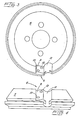
- the milling cutter 2 comprises a cutter body 4 having a plurality of insert pockets 6, each of the pockets having a back wall 8. There is also a bottom wall 10 and chip gash portion 12. The milling cutter would typically rotate in direction of rotation 5.
- the milling cutter further comprises an indexable insert 14 having opposed top 16 and bottom 18 surfaces joined by a peripheral wall 20 to form a polygonal body when viewed in plan.
- the peripheral wall on each side of the insert forms a cutting edge 22 at the juncture of one of the top and bottom surfaces.
- a clearance face 24 on each side of the insert joins the peripheral wall and the other of the top and bottom faces.
- the milling cutter further comprises means for holding the insert in the insert pocket so that one of said top or bottom surfaces abuts the back wall.
- a milling cutter station typically comprises a cutter body and associated hardware such as an insert and a nest. There would normally be several such stations. However, for purposes of illustration, only one such station is shown in the figures.
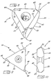
- the insert is in the shape of a diamond when viewed in plan and the adjacent sides intersect at the corners 36 and 38 of the diamond having the smaller included angles.
- the insert has four cutting positions. When placed so that the top faces u p, the cutting positions will be at the corners 36 and 38 . When the insert is flipped over so that the bottom face is up, the cutting positions again will be at the corners 36 and 38.
- a second clearance face 25 joins the peripheral wall 20 and the one of the top and bottom surfaces and extends from an end 40 of the cutting edge 22.
- a second cutting edge 23 is formed at the juncture of the peripheral wall and the other of the top and bottom surfaces and extends from an end 42 of the clearance face 24.
- a clearance face 24 or 25 and a cutting edge 22 or 23 will extend from each corner 44 of the insert.
- a clearance face 24 or 25 When traversing the periphery of the top or bottom surface, a clearance face 24 or 25 will always alternate with a cutting edge 22 or 23 so that each time the insert is indexed, a cutting edge and a clearance face will always be in proper cutting relation. That is, for each cutting position, each cutting edge will always have a complimentary clearance face.
- each insert is in the shape of a triangle and, most preferably, the insert has six cutting positions.
- Each corner 44 of the triangle will have a cutting position when viewed from the top surface.
- the insert is flipped over so as to be viewed from the bottom surface, there will be an additional three cutting positions at each corner 44.
- either embodiment of the inserts will be oriented with negative radial rake and positive axial rake angles.
- the means 26 for holding the insert comprises a pin member 46 and a central perforation 48 through the top and bottom surface of the insert.
- the pin member 46 engages the wall 50 of the perforation and threadedly engages at 52 the back wall 8 of the insert to firmly abut the insert pocket.
- the pin member is of the type shown in European Patent Application No. 81108772.5.
- the milling cutter may also comprise a nest 54 interposed between the insert and the insert pocket.
- an-indexable milling insert 14 comprises opposed top 16 and bottom 18 surfaces joined by a peripheral wall 20 to form a polygonal body when viewed in plan.
- the peripheral wall on each side of the insert forms a cutting edge 22 at the juncture of one of the top and bottom faces.
- Clearance face 24 on each side of the insert joins the peripheral wall and the other of the top and bottom surfaces.
- the insert is in the shape of a diamond when viewed in plan and adjacent sides intersect at the corners 36 and 38 of the diamond having the smaller included angles. It is most preferred that the insert has four cutting positions. When viewed from the top surface, there will be a cutting position at each of the corners 36 and 38, and when the insert is flipped over and viewed from the bottom, there will be two additional cutting positions, again at the corners 36 and 38.
- a second clearance face 25 joins the peripheral wall 20 and the one of the top and bottom surfaces and extends from an end 40 of the cutting edge 22.
- a second cutting edge 23 is formed at the juncture of the peripheral wall and the other of the top and bottom surfaces and extends from an end 42 of the clearance face 24.
- a clearance face 24 or 25 and a cutting edge 22 or 23 will extend from each corner of the insert.
- a clearance face 24 or 25 When traversing the periphery of the top or bottom surface, a clearance face 24 or 25 will always alternate with a cutting edge 22 or 23 so that each time the insert is indexed, a cutting edge and a clearance face will always be in proper cutting relation. That is, for each cutting position, a clearance face will always complement a cutting edge.
- the in is in the shape of a triangle, and most preferably, the insert has six cutting positions. There will be two cutting positions at each corner 44 of the triangle so that when viewed from the top, there will be three cutting positions, and when the insert is viewed from the bottom, there will be an additional three cutting positions.
Landscapes
- Engineering & Computer Science (AREA)
- Mechanical Engineering (AREA)
- Milling Processes (AREA)
Applications Claiming Priority (2)
| Application Number | Priority Date | Filing Date | Title |
|---|---|---|---|
| US42665082A | 1982-09-29 | 1982-09-29 | |
| US426650 | 1982-09-29 |
Publications (2)
| Publication Number | Publication Date |
|---|---|
| EP0104517A2 true EP0104517A2 (fr) | 1984-04-04 |
| EP0104517A3 EP0104517A3 (fr) | 1985-10-09 |
Family
ID=23691650
Family Applications (1)
| Application Number | Title | Priority Date | Filing Date |
|---|---|---|---|
| EP83108863A Withdrawn EP0104517A3 (fr) | 1982-09-29 | 1983-09-08 | Fraise et plaquette de coupe amovible pour celle-ci |
Country Status (8)
| Country | Link |
|---|---|
| EP (1) | EP0104517A3 (fr) |
| JP (1) | JPS59146710A (fr) |
| AU (1) | AU1875583A (fr) |
| DE (1) | DE104517T1 (fr) |
| DK (1) | DK445783A (fr) |
| ES (2) | ES287787Y (fr) |
| FI (1) | FI833474L (fr) |
| ZA (1) | ZA837100B (fr) |
Cited By (17)
| Publication number | Priority date | Publication date | Assignee | Title |
|---|---|---|---|---|
| US4597695A (en) * | 1985-03-11 | 1986-07-01 | Ingersoll Cutting Tool Company | Face milling apparatus with eight-edged insert |
| US5028175A (en) * | 1988-03-21 | 1991-07-02 | Gte Valenite Corporation | Indexable insert for roughing and finishing |
| US5114282A (en) * | 1988-03-21 | 1992-05-19 | Gte Valenite Corporation | Indexable insert for roughing and finishing |
| EP0488185A1 (fr) * | 1990-11-26 | 1992-06-03 | Mitsubishi Materials Corporation | Plaquette de coupe à jeter |
| EP0506098A1 (fr) * | 1991-03-28 | 1992-09-30 | Mitsubishi Materials Corporation | Outil rotatif |
| US5314269A (en) * | 1991-09-05 | 1994-05-24 | Mitsubishi Materials Corporation | Cutting insert and cutter |
| WO1995022425A1 (fr) * | 1994-02-19 | 1995-08-24 | Kennametal Hertel Ag Werkzeuge + Hartstoffe | Fraise |
| EP0760725A4 (fr) * | 1995-03-24 | 1997-07-09 | Iscar Ltd | Plaquette coupante |
| US5820308A (en) * | 1994-11-08 | 1998-10-13 | Ingersoll Cutting Tool Company | Plunge milling cutter |
| RU2124970C1 (ru) * | 1995-01-30 | 1999-01-20 | Кеннаметал Инк. | Врезная и торцевая фреза с универсальными гнездами для режущих пластин |
| US6722823B1 (en) | 2002-12-24 | 2004-04-20 | Kennametal Inc. | Milling cutter |
| US6851897B2 (en) * | 2001-07-09 | 2005-02-08 | Big Daishowa Seiki Co., Ltd. | Cutting tool insert and cutting tool |
| US7357603B2 (en) | 2002-12-24 | 2008-04-15 | Kennametal Inc. | Toolholder and cutting insert used therein |
| EP1782902A3 (fr) * | 2005-11-07 | 2010-12-08 | Sumitomo Electric Hardmetal Corp. | Plaquette de coupe remplaçable et fraise pour coins avec plaquettes de coupe remplaçables |
| US20140205388A1 (en) * | 2011-08-16 | 2014-07-24 | Seco Tools Ab | Indexable, double-sided cutting insert and cutting tool including such an insert |
| US9475136B2 (en) | 2013-07-30 | 2016-10-25 | Kennametal Inc. | High-speed milling cutter and cutting insert therefor |
| WO2018197141A1 (fr) * | 2017-04-27 | 2018-11-01 | Hartmetall-Werkzeugfabrik Paul Horn Gmbh | Plaquette de coupe et outil pour l'usinage d'une pièce par enlèvement de copeaux |
Families Citing this family (6)
| Publication number | Priority date | Publication date | Assignee | Title |
|---|---|---|---|---|
| JPS61151820U (fr) * | 1985-03-11 | 1986-09-19 | ||
| JP3120437B2 (ja) * | 1990-07-04 | 2000-12-25 | 三菱マテリアル株式会社 | スローアウエイチツプ |
| WO1992006811A1 (fr) * | 1990-10-15 | 1992-04-30 | Mitsubishi Materials Corporation | Outil de coupe et tete de coupe jetables |
| JP2530762Y2 (ja) * | 1991-03-15 | 1997-03-26 | 三菱マテリアル株式会社 | スローアウェイチップ |
| JP2560679Y2 (ja) * | 1991-12-26 | 1998-01-26 | 京セラ株式会社 | スローアウェイチップ |
| JP5309820B2 (ja) * | 2008-09-12 | 2013-10-09 | 三菱マテリアル株式会社 | 切削インサートおよびインサート着脱式転削工具 |
Family Cites Families (4)
| Publication number | Priority date | Publication date | Assignee | Title |
|---|---|---|---|---|
| FR2042765A5 (fr) * | 1969-04-10 | 1971-02-12 | Usap Utensileria Special | |
| US3818562A (en) * | 1972-07-19 | 1974-06-25 | Kysor Industrial Corp | Cutter body and blade therefor |
| SE419834B (sv) * | 1977-02-11 | 1981-08-31 | Seco Tools Ab | Vendsker och verktyg for hornfresning |
| US4470731A (en) * | 1981-07-08 | 1984-09-11 | General Electric Company | Milling cutter with adjustable finishing insert |
-
1983
- 1983-09-06 AU AU18755/83A patent/AU1875583A/en not_active Abandoned
- 1983-09-08 DE DE198383108863T patent/DE104517T1/de active Pending
- 1983-09-08 EP EP83108863A patent/EP0104517A3/fr not_active Withdrawn
- 1983-09-23 ZA ZA837100A patent/ZA837100B/xx unknown
- 1983-09-27 FI FI833474A patent/FI833474L/fi not_active Application Discontinuation
- 1983-09-28 DK DK445783A patent/DK445783A/da not_active Application Discontinuation
- 1983-09-28 JP JP58178400A patent/JPS59146710A/ja active Pending
- 1983-09-29 ES ES1983287787U patent/ES287787Y/es not_active Expired
-
1984
- 1984-09-17 ES ES535995A patent/ES535995A0/es active Granted
Cited By (23)
| Publication number | Priority date | Publication date | Assignee | Title |
|---|---|---|---|---|
| US4597695A (en) * | 1985-03-11 | 1986-07-01 | Ingersoll Cutting Tool Company | Face milling apparatus with eight-edged insert |
| US5028175A (en) * | 1988-03-21 | 1991-07-02 | Gte Valenite Corporation | Indexable insert for roughing and finishing |
| US5114282A (en) * | 1988-03-21 | 1992-05-19 | Gte Valenite Corporation | Indexable insert for roughing and finishing |
| EP0488185A1 (fr) * | 1990-11-26 | 1992-06-03 | Mitsubishi Materials Corporation | Plaquette de coupe à jeter |
| US5190417A (en) * | 1990-11-26 | 1993-03-02 | Mitsubishi Materials Corporation | Throwaway insert |
| EP0506098A1 (fr) * | 1991-03-28 | 1992-09-30 | Mitsubishi Materials Corporation | Outil rotatif |
| US5190418A (en) * | 1991-03-28 | 1993-03-02 | Mitsubishi Materials Corporation | Rotary cutter |
| US5314269A (en) * | 1991-09-05 | 1994-05-24 | Mitsubishi Materials Corporation | Cutting insert and cutter |
| WO1995022425A1 (fr) * | 1994-02-19 | 1995-08-24 | Kennametal Hertel Ag Werkzeuge + Hartstoffe | Fraise |
| US5820308A (en) * | 1994-11-08 | 1998-10-13 | Ingersoll Cutting Tool Company | Plunge milling cutter |
| RU2124970C1 (ru) * | 1995-01-30 | 1999-01-20 | Кеннаметал Инк. | Врезная и торцевая фреза с универсальными гнездами для режущих пластин |
| EP0760725A4 (fr) * | 1995-03-24 | 1997-07-09 | Iscar Ltd | Plaquette coupante |
| US6851897B2 (en) * | 2001-07-09 | 2005-02-08 | Big Daishowa Seiki Co., Ltd. | Cutting tool insert and cutting tool |
| US6722823B1 (en) | 2002-12-24 | 2004-04-20 | Kennametal Inc. | Milling cutter |
| US7357603B2 (en) | 2002-12-24 | 2008-04-15 | Kennametal Inc. | Toolholder and cutting insert used therein |
| EP1782902B1 (fr) | 2005-11-07 | 2018-01-03 | Sumitomo Electric Hardmetal Corp. | Plaquette de coupe remplaçable et fraise pour coins avec plaquettes de coupe remplaçables |
| EP1782902A3 (fr) * | 2005-11-07 | 2010-12-08 | Sumitomo Electric Hardmetal Corp. | Plaquette de coupe remplaçable et fraise pour coins avec plaquettes de coupe remplaçables |
| US20140205388A1 (en) * | 2011-08-16 | 2014-07-24 | Seco Tools Ab | Indexable, double-sided cutting insert and cutting tool including such an insert |
| US9039335B2 (en) * | 2011-08-16 | 2015-05-26 | Seco Tools Ab | Indexable, double-sided cutting insert and cutting tool including such an insert |
| US9475136B2 (en) | 2013-07-30 | 2016-10-25 | Kennametal Inc. | High-speed milling cutter and cutting insert therefor |
| WO2018197141A1 (fr) * | 2017-04-27 | 2018-11-01 | Hartmetall-Werkzeugfabrik Paul Horn Gmbh | Plaquette de coupe et outil pour l'usinage d'une pièce par enlèvement de copeaux |
| CN110352108A (zh) * | 2017-04-27 | 2019-10-18 | 硬质金属工具厂保罗霍恩有限公司 | 用于机加工工件的切削刀片和刀具 |
| US11278972B2 (en) | 2017-04-27 | 2022-03-22 | Hartmetall-Werkzeugfabrik Paul Hom GmbH | Cutting insert and tool for machining a workpiece |
Also Published As
| Publication number | Publication date |
|---|---|
| DK445783A (da) | 1984-03-30 |
| DK445783D0 (da) | 1983-09-28 |
| ZA837100B (en) | 1984-11-28 |
| FI833474A7 (fi) | 1984-03-30 |
| ES287787U (es) | 1986-05-01 |
| EP0104517A3 (fr) | 1985-10-09 |
| DE104517T1 (de) | 1984-07-19 |
| FI833474A0 (fi) | 1983-09-27 |
| ES8506486A1 (es) | 1985-08-01 |
| FI833474L (fi) | 1984-03-30 |
| AU1875583A (en) | 1984-04-05 |
| JPS59146710A (ja) | 1984-08-22 |
| ES535995A0 (es) | 1985-08-01 |
| ES287787Y (es) | 1987-01-16 |
Similar Documents
| Publication | Publication Date | Title |
|---|---|---|
| EP0104517A2 (fr) | Fraise et plaquette de coupe amovible pour celle-ci | |
| US4189264A (en) | Cutting insert and chip control assembly | |
| US4632607A (en) | Indexable cutting insert | |
| EP0579963B1 (fr) | Insert pour le coupage avec faible avance et faible pénétration | |
| US5333972A (en) | Special boring insert | |
| EP0464825B1 (fr) | Plaquette de coupe et outil de coupe | |
| US4597695A (en) | Face milling apparatus with eight-edged insert | |
| EP0571932B1 (fr) | Plaquettes de coupe à fraise interchangeables | |
| US5382118A (en) | Milling cutter insert | |
| EP0585871B1 (fr) | Plaquette de coupe pour une fraise | |
| US4248553A (en) | Cutting insert configuration | |
| EP0530831B1 (fr) | Plaquette de coupe et outil à plaquette | |
| EP0790094B1 (fr) | Plaquette de coupe et outil de coupe | |
| EP0873808A1 (fr) | Plaquettes de coupe pour une fraise disque | |
| EP0358623A1 (fr) | Plaquette de braquage pour machine-outil d'usinage | |
| EP0489702A2 (fr) | Plaquette et outil de coupe pour l'usinage à enlèvement de copeaux | |
| EP0037691A2 (fr) | Ensemble porte-outil avec plaquette de coupe interchangeable pour un outil de coupe | |
| EP0313044B1 (fr) | Plaquette de coupe | |
| US6764254B2 (en) | Throwaway insert and pin mirror cutter using the same | |
| JP3269245B2 (ja) | スローアウェイチップ及び切削工具 | |
| JP3185519B2 (ja) | スローアウェイチップ及び切削工具 | |
| EP0566085B1 (fr) | Plaquette de coupe à fraiser | |
| JP3003230B2 (ja) | スローアウェイチップ及びスローアウェイ式カッタ | |
| EP0112136A3 (fr) | Elément tranchant pour outils coupants | |
| US5556239A (en) | Positive cutting insert with compound clearance faces |
Legal Events
| Date | Code | Title | Description |
|---|---|---|---|
| PUAI | Public reference made under article 153(3) epc to a published international application that has entered the european phase |
Free format text: ORIGINAL CODE: 0009012 |
|
| AK | Designated contracting states |
Designated state(s): BE CH DE FR GB IT LI NL SE |
|
| EL | Fr: translation of claims filed | ||
| ITCL | It: translation for ep claims filed |
Representative=s name: DR. ING. A. RACHELI & C. |
|
| TCNL | Nl: translation of patent claims filed | ||
| DET | De: translation of patent claims | ||
| PUAL | Search report despatched |
Free format text: ORIGINAL CODE: 0009013 |
|
| AK | Designated contracting states |
Designated state(s): BE CH DE FR GB IT LI NL SE |
|
| 17P | Request for examination filed |
Effective date: 19860407 |
|
| 17Q | First examination report despatched |
Effective date: 19880429 |
|
| STAA | Information on the status of an ep patent application or granted ep patent |
Free format text: STATUS: THE APPLICATION IS DEEMED TO BE WITHDRAWN |
|
| 18D | Application deemed to be withdrawn |
Effective date: 19880331 |
|
| RIN1 | Information on inventor provided before grant (corrected) |
Inventor name: ERICKSON, ROBERT A. |