EP0104520A2 - Méthode et dispositif pour nettoyer et contrôler la surface interne d'une conduite - Google Patents
Méthode et dispositif pour nettoyer et contrôler la surface interne d'une conduite Download PDFInfo
- Publication number
- EP0104520A2 EP0104520A2 EP83108923A EP83108923A EP0104520A2 EP 0104520 A2 EP0104520 A2 EP 0104520A2 EP 83108923 A EP83108923 A EP 83108923A EP 83108923 A EP83108923 A EP 83108923A EP 0104520 A2 EP0104520 A2 EP 0104520A2
- Authority
- EP
- European Patent Office
- Prior art keywords
- pipe
- plugs
- compression chamber
- tube
- compression
- Prior art date
- Legal status (The legal status is an assumption and is not a legal conclusion. Google has not performed a legal analysis and makes no representation as to the accuracy of the status listed.)
- Withdrawn
Links
Images

Classifications
-
- B—PERFORMING OPERATIONS; TRANSPORTING
- B08—CLEANING
- B08B—CLEANING IN GENERAL; PREVENTION OF FOULING IN GENERAL
- B08B9/00—Cleaning hollow articles by methods or apparatus specially adapted thereto
- B08B9/02—Cleaning pipes or tubes or systems of pipes or tubes
- B08B9/027—Cleaning the internal surfaces; Removal of blockages
- B08B9/04—Cleaning the internal surfaces; Removal of blockages using cleaning devices introduced into and moved along the pipes
- B08B9/053—Cleaning the internal surfaces; Removal of blockages using cleaning devices introduced into and moved along the pipes moved along the pipes by a fluid, e.g. by fluid pressure or by suction
- B08B9/055—Cleaning the internal surfaces; Removal of blockages using cleaning devices introduced into and moved along the pipes moved along the pipes by a fluid, e.g. by fluid pressure or by suction the cleaning devices conforming to, or being conformable to, substantially the same cross-section of the pipes, e.g. pigs or moles
- B08B9/0553—Cylindrically shaped pigs
Definitions
- the invention relates to a method for automatically cleaning and checking pipes with the aid of plugs made of compressible material, in particular made of felt or foam, and a device for carrying out the method.
- the degree of contamination of the plugs allows conclusions to be drawn about the cleanliness of the inner tube surfaces.
- the difficulty of this method is that rags or plugs have to be laboriously inserted manually into the pipe to be treated. Since this procedure partly depends on the degree of soiling. Repeated several times on a pipe, this process is very cumbersome and time consuming.
- the treatment of an inner pipe surface of a 30 m long pipe can take up to an hour.
- Another disadvantage is the exposure of the operating personnel to solvent vapors and the constant contact with detergents.
- the inside of the pipe is treated by blasting with abrasive agents. This method is also complex, associated with health risks and, in many cases, moreover cannot be used or can only be used to a limited extent.
- the present invention was therefore based on the specification to provide a method for automatically cleaning and checking the inner surface of pipes with the aid of plugs made of compressible material, in particular made of felt or foam, and an associated device for carrying out the method, with which an automatic , quick and safe treatment of the inner tube wall is possible for the operating personnel.
- the object was achieved in that the plugs are first soaked with a cleaning, rinsing or lubricant, the plugs then in a compression chamber by pressing with one or more Press punches are compressed to such an extent that the diameter of the plugs has an undersize of a few tenths of a millimeter compared to the inside diameter of the pipe to be treated, the pipe is positioned in front of an opening in the compression chamber, and then the compressed plugs, which have a common longitudinal axis with the positioned pipe, are inserted into the pipe from the compression chamber, which is still in the compression position of the press ram, with the plugs intensively treating the inner wall of the pipe as it passes through the expansion of the compressible plug material and inspected after leaving the pipe and, depending on the inspection findings, about a signal if necessary further plugs are inserted into the pipe.
- the method according to the invention is based on the knowledge that compressible stopper material, brought to an undersize in relation to the inside diameter of the tube by pressing, can be conveniently and quickly inserted into a tube, which relaxes in the tube, that is, according to the material properties, such as those used for felt or certain types of foam is typical, expands in the tube.
- the resulting intimate contact of the now widened plug soaked with cleaning agent ensures intensive and gentle treatment of the inner pipe surface. In this way, forceful insertion of the stopper, e.g. avoided with mechanical aids, thus preventing pipe damage, and inserting the stopper into the pipe in a surprisingly quick manner, in fractions of a second.
- plugs are compressed one after the other by horizontal pre-compression and vertical final compression.
- a largely arbitrary plug start geometry can be adapted to the inner pipe geometry.
- the plugs are introduced into a cleaning, rinsing or lubricant circuit which is passed through the compression chamber and the pipe. Furthermore, it has proven to be particularly advantageous if, depending on the inspection findings given, the stopper is automatically inserted into the tube via a triggered signal or the inspected tube is automatically removed and a tube to be cleaned or checked is fed to the mouth of the compression chamber .
- the method according to the invention is advantageously carried out in a device in which a feed for plugs, which is provided with a shower for cleaning, rinsing or lubricating agents, is connected to a compression chamber, and the compression chamber comprises a press die, press ram, a transport means feed and a Contains mouth for receiving the tube.
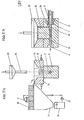
- Plugs roll out of a plug magazine (1) (see Fig. I) in which there is a supply of cylindrical plugs (11), for example made of felt, whose diameter is larger than the inside diameter of the pipe (9) to be treated ( 11) over an inclined plane (30) onto a sieve bar (26) and are pushed on it by means of a cyclically operating slide (29) under a shower (2) in the direction of a compression chamber (3).
- the shower (2) sprinkles the plugs (11) with washing, rinsing or solvent, which is fed from a storage container (24) via a pump (25). Excess detergent drips through the sieve bar (26) into a trough (31), from where it is returned to the storage container (24).
- the moistened stoppers (11) are pushed further and fall or roll into a press die (5) of the compression chamber (3).
- the plug (11) is correspondingly. formed channel (32) pressed and compressed into a cylinder (34) with an undersize of a few tenths of a millimeter relative to the pipe (9) to be treated.
- the stamp collar (33) simultaneously seals the compression chamber (3) from the outside. Excess detergent released during compaction can drain through the pipe (9) to be treated.
- This tube (9) is inserted into a mouth (8) provided with sealing elements (7), which has a correspondingly shaped tube inlet geometry and is located on the compression chamber (3).
- the compressed plug (34) and the tube (9) have a common axis (22).
- a transport medium for example compressed air
- the compressed plug (34) along the channel (32) is properly inserted into the pipe (9) to be treated and driven through.
- the compressed plug (34) expands according to the inside diameter of the pipe (9) and treats the inside wall of the pipe intensely when it is passed through by intimate contact.
- the compressed air plug is triggered manually, advantageously via a signal transmitter (16) or automatically. After passing through the pipe (9), the plug is inspected for contamination and examined. Visual and other control methods known per se can be used. Depending on the inspection findings, further plugs (11) can be driven through the pipe (9) via the signal transmitter (16). The operation is therefore unproblematic and harmless.
- the tube (9) is inserted into the mouth (8) by means of a controllable supply and discharge device (12) which is provided with a magazine (13) for untreated tubes and with a magazine (10) for treated tubes ) introduced.
- cube-shaped or columnar material As a starting material for the plugs, cube-shaped or columnar material (see Fig. II), e.g. Cubes (18) made of polypropylene can be used. It is particularly favorable if the compression chamber (3) contains horizontally working rams (14) and a vertically working ram (15). It is also advantageous if the press die (5), the press ram (4, 14, 15) and the mouth (8) are interchangeably arranged, since the changeover times are sometimes reduced when changing over to other pipe dimensions. _
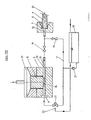
- the compressed stopper (34) is introduced into a detergent circuit (17).
- the detergent flow is passed alternately through the compression chamber (3) or behind it into the channel (32) between a correspondingly dimensioned through valve (19) and the mouth (8) through the pipe (9).
- the detergent is sucked from a detergent storage tank (28) by a pump (27) and passed through the pipe (9) to be cleaned via a two-way valve (20).
- the seal (7) prevents detergent from escaping.
- the compression chamber (3) is loaded with a stopper (11). Then the previously closed valve (19) and a further previously also closed three-way valve (21) are opened and after a short delay the valve (20) is closed.
- curved pipes can also be cleaned and checked in many cases.
- suitable cleaning agents also allows the treatment of calcified pipes, since the plug insertion method according to the invention, in conjunction with the plug expansion in the pipe to be treated, leads to particularly intensive lime removal.
- Pipes with an angular cross-sectional profile can also be cleaned and inspected in the manner according to the invention.
- plugs made of foam have proven themselves well, while felt plugs are outstandingly suitable for the treatment according to the invention of already relatively clean pipes because of their special contact pressure when "rising” from the compressed, ie compressed, state.
- the compression chamber (3) and its components can be made of metal or plastic, e.g. Teflon.
- Treatment agent alcohol
Landscapes
- Physics & Mathematics (AREA)
- Fluid Mechanics (AREA)
- Engineering & Computer Science (AREA)
- Mechanical Engineering (AREA)
- Cleaning In General (AREA)
Applications Claiming Priority (2)
| Application Number | Priority Date | Filing Date | Title |
|---|---|---|---|
| DE3235785 | 1982-09-28 | ||
| DE3235785 | 1982-09-28 |
Publications (2)
| Publication Number | Publication Date |
|---|---|
| EP0104520A2 true EP0104520A2 (fr) | 1984-04-04 |
| EP0104520A3 EP0104520A3 (fr) | 1988-01-13 |
Family
ID=6174305
Family Applications (1)
| Application Number | Title | Priority Date | Filing Date |
|---|---|---|---|
| EP83108923A Withdrawn EP0104520A3 (fr) | 1982-09-28 | 1983-09-09 | Méthode et dispositif pour nettoyer et contrôler la surface interne d'une conduite |
Country Status (3)
| Country | Link |
|---|---|
| EP (1) | EP0104520A3 (fr) |
| JP (1) | JPS59136182A (fr) |
| ZA (1) | ZA837035B (fr) |
Cited By (2)
| Publication number | Priority date | Publication date | Assignee | Title |
|---|---|---|---|---|
| EP0580314A1 (fr) * | 1992-07-24 | 1994-01-26 | Matsui Manufacturing Co., Ltd. | Procédé et dispositif de nettoyage de l'intérieur d'un tube |
| EP0581616A1 (fr) * | 1992-07-31 | 1994-02-02 | Petroleo Brasileiro S.A. - Petrobras | Méthode d'enlèvement de liquide dans des systèmes de tubes, utilisant un tampon cylindrique mouvant |
Family Cites Families (3)
| Publication number | Priority date | Publication date | Assignee | Title |
|---|---|---|---|---|
| US3531813A (en) * | 1968-09-17 | 1970-10-06 | Combustion Eng | Tube cleaning pellet gun |
| US3631555A (en) * | 1970-03-09 | 1972-01-04 | Combustion Eng | Tube-cleaning pellet gun |
| JPS5714193A (en) * | 1980-06-30 | 1982-01-25 | Hitachi Ltd | Distributing and controlling method of cleaning balls |
-
1983
- 1983-09-09 EP EP83108923A patent/EP0104520A3/fr not_active Withdrawn
- 1983-09-21 ZA ZA837035A patent/ZA837035B/xx unknown
- 1983-09-28 JP JP58178390A patent/JPS59136182A/ja active Pending
Cited By (2)
| Publication number | Priority date | Publication date | Assignee | Title |
|---|---|---|---|---|
| EP0580314A1 (fr) * | 1992-07-24 | 1994-01-26 | Matsui Manufacturing Co., Ltd. | Procédé et dispositif de nettoyage de l'intérieur d'un tube |
| EP0581616A1 (fr) * | 1992-07-31 | 1994-02-02 | Petroleo Brasileiro S.A. - Petrobras | Méthode d'enlèvement de liquide dans des systèmes de tubes, utilisant un tampon cylindrique mouvant |
Also Published As
| Publication number | Publication date |
|---|---|
| ZA837035B (en) | 1984-05-30 |
| JPS59136182A (ja) | 1984-08-04 |
| EP0104520A3 (fr) | 1988-01-13 |
Similar Documents
| Publication | Publication Date | Title |
|---|---|---|
| DE68913473T2 (de) | Vorrichtung und Verfahren zur Reinigung vor Ort und Inbetriebnahme einer Anordnung von Düsen. | |
| EP2609310B1 (fr) | Procede et dispositif pour le decalaminage de corps creux, en particulier de conduits d'admission et de soupapes de moteur a combustion interne | |
| DE69307253T2 (de) | Verfahren zum Auskleiden der Innenwand eines Rohres | |
| DE2401120C3 (de) | Verfahren und Anlage zum Befüllen von Flüssigkeitskreisläufen | |
| DE69410018T2 (de) | Vorrichtung zur Reinigung von Rohren mit verformbaren Schwammkugeln | |
| EP0104520A2 (fr) | Méthode et dispositif pour nettoyer et contrôler la surface interne d'une conduite | |
| DE2927324C2 (en) | Cleaning device for concrete pump - has chamber containing cleaning ball, moved from external disengaged position into injection position | |
| DE102012014551A1 (de) | Reinigungsanlage und Reinigungsverfahren | |
| DE8227161U1 (de) | Vorrichtung zum reinigen und kontrollieren der innenoberflaeche von rohren | |
| DE4432503C2 (de) | Verfahren zum Reinigen der Hohlkörper eines Wärmetauschers und Vorrichtung zur Durchführung des Verfahrens | |
| DE2112881A1 (de) | Verfahren und Vorrichtung zum Abstreifen von Behaeltern von einem Stempelteil in einer Ziehpresse | |
| DE2252360A1 (de) | Verfahren und vorrichtung zum reinigen einer fluessigkeitsrohrleitung | |
| DE2645938A1 (de) | Verfahren und vorrichtung fuer die reinigung und die beseitigung von verbrennungsrueckstaenden insbesondere bei heizkesselrohren | |
| DE4320095A1 (de) | Verfahren und Vorrichtung zur dosierten Einbringung von Pflege-, Reinigungs- und/oder Desinfektionsflüssigkeiten in zahnärztliche Absauganlagen | |
| DE10055127A1 (de) | Verfahren und Vorrichtung zur Reinigung von Gegenständen mittels eines komprimierten Reinigungsfluides | |
| DE19701010A1 (de) | Verfahren zur Sanierung der Innenwände festverlegter Rohrleitungen | |
| EP0361129A2 (fr) | Méthode et dispositif pour le nettoyage des bouteilles | |
| DE4209439C2 (de) | Verfahren und Vorrichtung zur Entleerung und Entsorgung von flüssigen und gasförmigen Medien aus einem Behälter und damit verbundenen Rohrleitungen | |
| DE2047542A1 (fr) | ||
| DE102010005760A1 (de) | Wellrohr-Innenreinigung und Vorrichtung dazu | |
| DE10343243B4 (de) | Verfahren und Vorrichtung zum Spülen und Entleeren eines mit feststoffartigen Rückständen gefüllten Rückstandtanks einer biologischen Kläranlage | |
| DE102004047935B3 (de) | Vorrichtung zur Reinigung von Walzenoberflächen in Druckmaschinen | |
| DE9203905U1 (de) | Vorrichtung zur Entleerung und Entsorgung von flüssigen und gasförmigen Medien aus einem Behälter und damit verbundenen Rohrleitungen | |
| DE4431424A1 (de) | Verfahren zum Entfernen von Quecksilber aus Rohren | |
| DE102015100157A1 (de) | Klebeanlage für einen Zweikomponentenklebstoff sowie Verfahren zum Betrieb einer solchen Klebeanlage |
Legal Events
| Date | Code | Title | Description |
|---|---|---|---|
| PUAI | Public reference made under article 153(3) epc to a published international application that has entered the european phase |
Free format text: ORIGINAL CODE: 0009012 |
|
| 17P | Request for examination filed |
Effective date: 19830909 |
|
| AK | Designated contracting states |
Designated state(s): AT DE FR GB |
|
| PUAL | Search report despatched |
Free format text: ORIGINAL CODE: 0009013 |
|
| AK | Designated contracting states |
Kind code of ref document: A3 Designated state(s): AT DE FR GB |
|
| STAA | Information on the status of an ep patent application or granted ep patent |
Free format text: STATUS: THE APPLICATION HAS BEEN WITHDRAWN |
|
| 17Q | First examination report despatched |
Effective date: 19880629 |
|
| 18W | Application withdrawn |
Withdrawal date: 19880802 |
|
| RIN1 | Information on inventor provided before grant (corrected) |
Inventor name: WOLFF, WILLI Inventor name: KNICHELMANN, WINFRIED Inventor name: BADER, EBERHARDT |