EP0104557A2 - Balance - Google Patents
Balance Download PDFInfo
- Publication number
- EP0104557A2 EP0104557A2 EP83109177A EP83109177A EP0104557A2 EP 0104557 A2 EP0104557 A2 EP 0104557A2 EP 83109177 A EP83109177 A EP 83109177A EP 83109177 A EP83109177 A EP 83109177A EP 0104557 A2 EP0104557 A2 EP 0104557A2
- Authority
- EP
- European Patent Office
- Prior art keywords
- transducer
- slots
- elongate
- platform
- elements
- Prior art date
- Legal status (The legal status is an assumption and is not a legal conclusion. Google has not performed a legal analysis and makes no representation as to the accuracy of the status listed.)
- Withdrawn
Links
Images


Classifications
-
- G—PHYSICS
- G01—MEASURING; TESTING
- G01G—WEIGHING
- G01G3/00—Weighing apparatus characterised by the use of elastically-deformable members, e.g. spring balances
- G01G3/12—Weighing apparatus characterised by the use of elastically-deformable members, e.g. spring balances wherein the weighing element is in the form of a solid body stressed by pressure or tension during weighing
- G01G3/14—Weighing apparatus characterised by the use of elastically-deformable members, e.g. spring balances wherein the weighing element is in the form of a solid body stressed by pressure or tension during weighing measuring variations of electrical resistance
- G01G3/1402—Special supports with preselected places to mount the resistance strain gauges; Mounting of supports
-
- G—PHYSICS
- G01—MEASURING; TESTING
- G01G—WEIGHING
- G01G3/00—Weighing apparatus characterised by the use of elastically-deformable members, e.g. spring balances
- G01G3/12—Weighing apparatus characterised by the use of elastically-deformable members, e.g. spring balances wherein the weighing element is in the form of a solid body stressed by pressure or tension during weighing
Definitions
- the invention relates to a scale with strain gauges and with upper and lower horizontal components, which are arranged in parallel planes to each other.
- a platform for a scale in which transducer beams with strain gauges or strips are formed as integral components of the platform is disclosed in U.S. Patent 4,261,429. Thereafter, each transducer beam with strain gauges is formed in the platform with a free, flexible end and with a fixed or foot end integrated into the plate as part of the platform. Strain gauges or strips are attached to this flexible transducer beam.
- a platform, in which the transducer bars with strain gauges are designed as integral parts of the platform is referred to below as a "standardized transducer plate” or simply as a "standardized plate".
- U.S. U.S. Patent 4,261,429 discloses groups of four holes are drilled through the plates. A plurality of cuts are then milled or otherwise formed into the platform from the side so that the cuts run inward from the platform edge. Two cuts run parallel to each other so that each cut connects two holes to form a beam structure. Of the four holes in a group, one is drilled at the fixed end of each cut, while the other hole is drilled between the fixed end and the free end of each transducer beam with strain gauges.
- All strain gauges connected to the beam structures are electronically connected to each other to form bridge circuits in order to obtain a weight display for the scale.
- Such standardized transducer plate devices or platforms are built into the scales according to European patent application No. 0065 176.
- This patent application describes scales with means to minimize weighing errors that result from exposure to a short-term horizontal load.
- the scales include coupling means to introduce vertical load components into the transducer beams with strain gauges while substantially reducing or preventing the introduction of shear load components or lateral load components into the transducer beams with strain gauges that are integral with the platform.
- a load to be measured is effective on the upper of two horizontal platforms parallel to each other.
- the transducer bars with strain gauges are formed integrally with the lower horizontal platform.
- Force-transmitting rods or arms are attached to the transducer beams with strain gauges in the lower platform in order to transmit a vertical load from the upper platform to the respective flexible transducer beams with strain gauges using a ball and ball socket coupling, in which a hardened ball against there is a concave or curved surface that has a radius of curvature that is greater than the radius of the sphere.
- Such coupling with first and second curved surfaces transfers vertical force components from the upper horizontal platform to the transducer bar with strain gauges, while such a coupling evades horizontal force components and substantially prevents the transmission of horizontal force components between the upper and lower horizontal platforms.
- the coupling with two curved contact surfaces with different rounding radius is enclosed by a flexible sleeve made of rubber or similar material.
- the sleeve is preferably attached at its ends, so that there is a damping of lateral vibrations.
- the sleeve also protects the coupling against contamination.
- vertical force components are applied from the upper horizontal plate to the transducer beams with strain gauges by means of a laterally flexible suspension, e.g. a cable suspension.
- a laterally flexible suspension e.g. a cable suspension.
- Such cable suspensions also substantially prevent the transfer of horizontal force components between the upper and lower horizontal platforms.
- Scales with standardized plates have many advantages, particularly in their low profile, ease of manufacture and accuracy.
- a massive platform is relatively heavy and requires corresponding material costs.
- the weight and cost factor increases with the load limit of the scale, e.g. a single platform with an aluminum plate with the dimensions 762 x 762 x 12.7 mm weighs approximately 2 0 , 45 kg and for a scale with a load limit of approx. 45 0 kg costs about DM 27 0 .
- such scales if they are not manufactured very carefully, can be sensitive to torsional force components, which can result in falsifying influences on the weight display.
- FIG. 1 shows a conventional platform 1 with standardized transducer plates, as is disclosed in US Pat. No. 4,261,429.
- the platform 1 is made of metal, for example from an aluminum alloy, which can be used for this purpose.
- a suitable wall thickness for this platform 1 is, for example, 4.6 mm to 12.7 mm for a load range of approximately 13.6 to 9 09 kg. Alloy or stainless steel plates can be used for scales with higher load ranges.
- Four groups 2 of boreholes 6 are arranged completely drilled through the platform 1. The position of the hole groups can be different relative to the platform.
- the groups of holes are usually arranged in the vicinity of the corners of the platform, as shown in FIG.
- a pair of slots 7 are cut in the platform 1 in each group of holes 6, e.g. these cuts are sawn, machined, or otherwise milled so that each cut extends inwardly from an edge of the platform to connect two holes to the edge to provide a transducer beam 11 with strain gauges as an integral unit with the platform structure form.
- Strain sensors 15 and 16, e.g. Strain gauges are usually attached to the beam 11, e.g. with adhesive.
- the strain gauges are preferably each arranged between the holes 6.
- the diameter of the holes, distances and the wall thickness of the platform will depend on the required load ranges or load limits of the scale. These dimensions are also determined with regard to the sensitivity of the balance.
- FIG. 2 shows, for example, a solution for the manufacture of a platform according to the present invention.
- the platform is designed as a frame structure in order to reduce material costs and weight.
- the "platform" 20 contains a frame structure which is made of elongated elements 22 and 24 which are arranged in a common plane parallel to one another and at a distance from one another. These elongated elements 22 and 24 can be produced from the same metals and with the same wall thickness and length as described with reference to the platform 1 in FIG. 1. Normal profile material can also be used to make this produce elongated frame members 22 and 24.
- the frame members 22 and 24 are connected to third and fourth elongate connecting members 25 and 26 to form a solid frame structure. The connection can usually be carried out by riveting, welding, with nuts and screws or the like.
- transducer bars with strain gauges or strips are formed at each end of the elements 22 and 24 as an integral unit.
- the transducer bars with strain gauges 3 0, 31, 32 and 33, 22 and 24 are prepared in-the respective ends of the elements the same way as described in FIG. 1
- the frame can have a shape for lower load limits, as shown in FIG. 3.
- the parallel elongated frame members 22 and 24 are spaced apart by a single connecting cross piece 28 and connected to form a solid structure to form an H shape.
- the platform 35 in FIG. 3 corresponds to the platform 20 in FIG. 2; therefore the same reference numerals have been used for the same parts.
- FIG. 4 Yet another embodiment of a platform 4o with an X or cross shape is illustrated in FIG. 4.
- the elongated frame members 42 and 44 are joined at the crossing point to form a solid structure.
- FIG. 4a shows how the elongated elements 42 and 44 are provided with cutouts in the intersection area in order to be able to interlock, so that the lower surfaces of the elements 42 and 44 lie in a common plane.
- a platform scale with a maximum load of about 454 kg, for example, by using a platform with a normalized Meßwandlerplatte, according to figure 2 are manufactured, thus the weight of the platform about 6 0% to 7o% reduced compared to the weight of an embodiment according to Figure 1 , whereby a considerable reduction in material costs is achieved.
- Experiments with a platform scale with a load limit of 454 kg and with a platform according to 2o in Figure 2 have shown that the frame has a completely equivalent operating behavior as a standardized one-piece plate according to Figure 1.
- a platform scale with a load limit of 68 kg and with The platform frame construction according to ⁇ 35 in FIG. 3 was built and tested and it was found that this balance had an equivalent operating behavior as a balance with a one-piece standardized battery with the same load limit according to FIG. 1.
- support feet are arranged within the flexible or free end of the transducer beams on the platform. This is fine for scales with larger dimensions. If, however, the feet are arranged within the transducer bars in scales with smaller dimensions, the scales may tip over when the load is placed close to the side edges.
- the invention avoids tilting by preferably placing the feet as close as possible to the edge of the frame, as shown in Figure 5.
- the transducer beams 5o form integral parts in the end of the elongated frame elements 55, so that the free, flexible ends 52 of the transducer beams 5o are arranged at a distance from the respective end 54 of the elongated frame elements 55. This distance defines a flex-resistant "dead" area 56 between the transducer beam 50 and the end 54 of the elongated frame element 55.
- the foot 58 is in each case at the free end 54 of the frame / element 55 with an adjustable screw 52 'in a threaded bushing 58 'fixed in the bending-resistant area 56.
- the screw 52 ' serves as an adjustment device for the foot 58 in order to level the balance.
- a group of six boreholes 6o are drilled in two rows entirely through the elongated element 55.
- Two elongated slots 62 are milled, cut, or otherwise formed through the elongated member to connect the holes 6o.
- a transverse gap 64 is cut at one end. This transverse gap can be arranged at one or the other of the two ends.
- the integral transducer beam 5o is oriented in the direction of the central longitudinal axis 55 'of the element 55 with the free flexible end 52 in the direction of the next end 54.
- the foot end that enters element 55 is oriented in the direction of the geometric center of element 55.
- Strain gauges 65 are fixed between the pairs of boreholes 6o on the beam, as shown in FIGS. 5 and 6.
- the adjustable screw 52 ' extends through the threaded bushing 58'.
- the load on an upper platform 59 is transmitted through a loading arm 61 which is attached to the free end of the beam 5 0 with a screw and a spacer on the beam 5o.
- a ball with ball socket bearing 62 is effectively inserted between the loading arm 61 and the upper platform 59.
- transducer beam and the support feet is shown in figures, for example 6, 6a and 6b, in which the transducer beams 7o with strain gauges are formed in the manner already described in the end of the elongated frame elements 72.
- the slots 73 extend to the edge 7 0 '.
- the support feet 74 are each mounted on a bridge 75, which bridges the transducer beam 7o in the elongated element 72 from one connecting means 76 to the other. By means of this bridge 75, the feet 74 are placed exactly centrally and symmetrically below the loading point.
- This device has the important advantage that undesirable loads or moments are not introduced into the balance because the torsional forces in both directions along and across the elongate element 72 are eliminated. This is particularly the case when the frame structure uses a ball-and-socket joint bearing, as is described in more detail in European patent application 00 65 176.
- the platform 59 is not shown in FIGS. 5 and 6 due to the fact that it is overnight.
- the load on the transducer beam 7o in FIGS. 6, 6a and 6b is the same as in FIGS. 5 and 5a.
- the loading arm 61 is attached to the free end of the beam 7o with a spacer 81. If necessary, an overload stop 82 can be used at the free end of the beam 7o as shown. Spacers 75 'are also inserted between the bridge 75 and the parts of the elements 72 outside the beam 7o so that the beam 7o can bend.
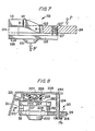
- FIG. 7 shows a corner of a frame structure according to the invention, which is built into a balance according to US Pat. No. 4,261,429.
- the effect of the burden, which acts, for example, on the converter bar 32 in FIG. 7 is shown in an exaggerated manner. This is also the case in FIG. 5a.
- the frame structure 35 according to FIG. 3 is shown in section at the end of the elongated frame element 34.
- the transducer bar with strain gauges 32 is shown in a bent position because a load P acts on the frame structure.
- the strain gauges 121 are under tension, the strain gauges 122 are under pressure.
- the bend of the transducer beam 32 is limited by an overload stop 127, as shown. Further overload stops, not visible in FIG. 7, are provided in front of and behind the spacer 124, relative to the image plane.
- each loading arm 125 is attached to the spacer 124 by a connecting means 126, e.g. B. a screw or the like attached.
- the inner end of each loading arm 125 extends far enough inward relative to elongated member 24 to cooperate with an overload stop 127, which may be an adjustable screw in a threaded hole 127 '.
- FIG. 8 shows a section of the end of an elongated frame element in a different type of suspension system for weighing platforms.
- a frame structure 2o or 3o or 4o according to the examples 2, 3 or 4 forms the lower horizontal link with a foot 2 00 , which is mounted on a frame structure element 24, as shown, for example, in FIG. 6a.
- the second platform 229 forms the second horizontal link or top platform on which the load is applied.
- a load placed on the upper platform 229 is transmitted to the lower frame platform 20 with a coupling means 221, in particular to the transducer beam 32 at the ends of the platform frame elements 24.
- This coupling means 221 contains a force transmission arm 280, which at the free end of the Transducer bar 32 z. B.
- An adjustable stop for example a stop screw 212 in a threaded hole at the free end of the power transmission arm 28o, serves as a stop at maximum load against the upward surface of the frame / element 24 of the platform 2 0 in order to limit the bending of the transducer beam 32.
- Another overload stop (at 32) is not shown, but is located either behind or in front of the image plane.
- the coupling means 22 to apply vertical loads to the platform 2o, includes a hardened steel pan 222 that is attached to the force transmission arm 28o above and approximately midway between the strain gauges 206 and 2o7.
- the pan has 222 a spherical cap 223, which represents a first curved surface with a given rounded radius, which is greater than the rounded radius of a hardened steel ball 224, which represents a second curved surface.
- a holding means for the ball 224 consists of a flexible length of a rubber tube or a rubber hose 225, which holds the steel ball 224 in its position in the spherical cap 223.
- the flexible rubber hose 225 is fastened at its upper end in a holding member 226 which is directed downwards from the upper platform 229.
- the flexible hose 225 can be secured in the holding member 226 with adhesive or the like.
- Retainer 226 may be welded to the underside of upper platform 229, as shown at 231.
- a further shim not shown, can also be provided.
- the hardened steel plate 227 and the shim, if one is used, can be glued on.
- the ball-and-socket coupling essentially prevents the transmission of horizontal forces or lateral force components to the lower platform 2o.
- some limitation on the relative horizontal movements is desirable.
- One such limitation is the flexible hose 225, which limits or dampens small loads in the horizontal direction.
- a collar bolt 214 limits greater horizontal loads when the bolt 214 bears against the surface of the respective borehole 216 in the elongated frame platform element 24.
- the structure of the coupling is the same at each end of the elongated frame platform elements that form the corners of the platform 2o.
- the collar bolt 214 can also be arranged to protrude through a suitable hole or bore 216 in the cross member of the frame structure.
- a flexible cable suspension can be used in combination with the present invention.
- Such a suspension is described in European patent application 0065 176 with reference to FIG. 7.
- the present invention can be used not only in single platform scales but also in double platform scales.
- Various types of couplings can be used in combination with the present invention to transmit the loading forces to the transducer beams.
- the two elongate frame members 42 'and 44 4 in Figure 4b can be attached to one another in any common manner in the intersection area without both links having to be in the same horizontal plane. Spacers, not shown, would then be used at the ends of one of the elements 42 'or 44' to compensate for the height difference.
- each of the load application examples can be used at every corner of the scale, or rather at each end of the elongated elements that form the frame structure.
- the flexible hose 225 in FIG. 8 could be omitted if this is desired.
- the use of a flexible hose 225 has the advantage that the correct damping of any movements of the balance parts relative to one another is achieved with this hose.
Landscapes
- Physics & Mathematics (AREA)
- General Physics & Mathematics (AREA)
- Measurement Of Force In General (AREA)
- Investigating Strength Of Materials By Application Of Mechanical Stress (AREA)
- Measurement Of Length, Angles, Or The Like Using Electric Or Magnetic Means (AREA)
- Testing Of Balance (AREA)
- Vehicle Cleaning, Maintenance, Repair, Refitting, And Outriggers (AREA)
Applications Claiming Priority (2)
| Application Number | Priority Date | Filing Date | Title |
|---|---|---|---|
| US06/424,485 US4506746A (en) | 1982-09-27 | 1982-09-27 | Gaged plate transducer weighing apparatus |
| US424485 | 1982-09-27 |
Publications (2)
| Publication Number | Publication Date |
|---|---|
| EP0104557A2 true EP0104557A2 (fr) | 1984-04-04 |
| EP0104557A3 EP0104557A3 (fr) | 1985-12-11 |
Family
ID=23682790
Family Applications (1)
| Application Number | Title | Priority Date | Filing Date |
|---|---|---|---|
| EP83109177A Withdrawn EP0104557A3 (fr) | 1982-09-27 | 1983-09-16 | Balance |
Country Status (4)
| Country | Link |
|---|---|
| US (1) | US4506746A (fr) |
| EP (1) | EP0104557A3 (fr) |
| JP (1) | JPS5979813A (fr) |
| AU (1) | AU1956183A (fr) |
Cited By (4)
| Publication number | Priority date | Publication date | Assignee | Title |
|---|---|---|---|---|
| WO1991018268A1 (fr) * | 1990-05-16 | 1991-11-28 | Edward Victor Byers | Balance a bascule |
| WO1993023723A1 (fr) * | 1992-05-11 | 1993-11-25 | Simons Gerald S | Detecteur de charge et appareil de support de charge |
| FR2980571A1 (fr) * | 2011-09-27 | 2013-03-29 | Seb Sa | Capteur de forces a butee integree et balance integrant un tel capteur |
| CN101738244B (zh) * | 2008-11-25 | 2013-04-10 | 国际道路动力有限公司 | 公路车辆的车轮和/或车轴载荷的测量 |
Families Citing this family (17)
| Publication number | Priority date | Publication date | Assignee | Title |
|---|---|---|---|---|
| US4600066A (en) * | 1983-05-19 | 1986-07-15 | Reliance Electric Company | Load cell apparatus |
| EP0166168B1 (fr) * | 1984-05-18 | 1988-04-06 | Pietzsch Aktiengesellschaft | Balance pour mesurer la charge d'une roue |
| US4949799A (en) * | 1986-02-03 | 1990-08-21 | Wernimont T August | Electronic weighing structure |
| JPH01502953A (ja) * | 1986-04-30 | 1989-10-05 | スタンダード・テレフオンズ・アンド・ケーブルズ・ピー・テイ・ワイ・リミテッド | 電話保護回路 |
| JPS63105037U (fr) * | 1986-12-24 | 1988-07-07 | ||
| US4714121A (en) * | 1987-02-03 | 1987-12-22 | Kroll William P | Wheel scale assembly |
| EP0305452A1 (fr) * | 1987-03-11 | 1989-03-08 | KELLENBACH, Arthur | Element de transmission de forces |
| US4785896A (en) * | 1987-10-13 | 1988-11-22 | Revere Corporation Of America | Load sensing structure for weighing apparatus |
| US4979581A (en) * | 1988-05-27 | 1990-12-25 | Kroll William P | Low profile wheel scale assembly |
| EP0533777A1 (fr) * | 1990-06-14 | 1993-03-31 | KELLENBACH, Arthur | Balance |
| US6555767B1 (en) | 2000-08-22 | 2003-04-29 | Flintec, Inc. | Composite load cell |
| US6755087B2 (en) * | 2001-11-26 | 2004-06-29 | Interface, Inc. | Load cell having overload protection |
| WO2004055624A2 (fr) * | 2002-12-02 | 2004-07-01 | Conair Corporation | Systeme de controle de bascule et eponge |
| US7048096B2 (en) * | 2003-12-08 | 2006-05-23 | Russell Ozechowski | Incremental braking apparatus and method of braking |
| CN202661155U (zh) * | 2009-06-30 | 2013-01-09 | 新光电子株式会社 | 分力缓冲装置和使用它的台秤 |
| EP3370043A1 (fr) | 2017-03-02 | 2018-09-05 | Mettler-Toledo (Albstadt) GmbH | Balance dotée d'un écran tactile incorporé dans la surface de plateforme réceptrice de charge |
| US12379241B2 (en) | 2021-05-17 | 2025-08-05 | Pelstar, Llc | Tray mounting assembly for a scale |
Family Cites Families (8)
| Publication number | Priority date | Publication date | Assignee | Title |
|---|---|---|---|---|
| US2899191A (en) * | 1959-08-11 | Electrically actuated weighing device | ||
| US4223752A (en) * | 1979-02-01 | 1980-09-23 | Belcher Claude A | Scale employing wheatstone-type bridges and strain gages |
| US4261429A (en) * | 1979-12-19 | 1981-04-14 | Hottinger Baldwin Measurements, Inc. | Unitized weighing apparatus and method for making such an apparatus |
| JPS5746129A (en) * | 1980-09-05 | 1982-03-16 | Tokyo Electric Co Ltd | Electronic balance |
| JPS5782720A (en) * | 1980-11-12 | 1982-05-24 | Kubota Ltd | Weighing machine |
| US4411327A (en) * | 1981-05-14 | 1983-10-25 | Hottinger Baldwin Measurements, Inc. | Apparatus for applying a load to a strain gage transducer beam |
| US4396079A (en) * | 1981-07-29 | 1983-08-02 | Sensor Developments, Inc. | Weighing system |
| EP0116170A3 (fr) * | 1983-01-17 | 1985-01-09 | Hottinger Baldwin Messtechnik Gmbh | Balance avec fléaux capteurs en forme de barre |
-
1982
- 1982-09-27 US US06/424,485 patent/US4506746A/en not_active Expired - Lifetime
-
1983
- 1983-09-16 EP EP83109177A patent/EP0104557A3/fr not_active Withdrawn
- 1983-09-21 JP JP58176155A patent/JPS5979813A/ja active Pending
- 1983-09-26 AU AU19561/83A patent/AU1956183A/en not_active Abandoned
Cited By (7)
| Publication number | Priority date | Publication date | Assignee | Title |
|---|---|---|---|---|
| WO1991018268A1 (fr) * | 1990-05-16 | 1991-11-28 | Edward Victor Byers | Balance a bascule |
| GB2260619A (en) * | 1990-05-16 | 1993-04-21 | Edward Victor Byers | Weighing machine |
| GB2260619B (en) * | 1990-05-16 | 1994-05-11 | Edward Victor Byers | Weighing machine |
| WO1993023723A1 (fr) * | 1992-05-11 | 1993-11-25 | Simons Gerald S | Detecteur de charge et appareil de support de charge |
| CN101738244B (zh) * | 2008-11-25 | 2013-04-10 | 国际道路动力有限公司 | 公路车辆的车轮和/或车轴载荷的测量 |
| FR2980571A1 (fr) * | 2011-09-27 | 2013-03-29 | Seb Sa | Capteur de forces a butee integree et balance integrant un tel capteur |
| WO2013045797A1 (fr) * | 2011-09-27 | 2013-04-04 | Seb S.A. | Capteur de forces a butee integree et balance integrant un tel capteur |
Also Published As
| Publication number | Publication date |
|---|---|
| US4506746A (en) | 1985-03-26 |
| EP0104557A3 (fr) | 1985-12-11 |
| JPS5979813A (ja) | 1984-05-09 |
| AU1956183A (en) | 1984-04-05 |
Similar Documents
| Publication | Publication Date | Title |
|---|---|---|
| EP0104557A2 (fr) | Balance | |
| DE2556428C3 (de) | Wägevorrichtung | |
| EP0065176A2 (fr) | Dispositif pour appliquer une charge à un support sous forme d'une poutre | |
| DE3331708C3 (de) | Vorrichtung zur Kontrolle und/oder Eichung einer Drehmomentmeßvorrichtung | |
| DE2710893A1 (de) | Brueckenwaage | |
| DE69000454T2 (de) | Wiegevorrichtung mit dehnungmessstreifen. | |
| DE2121357B2 (de) | Lastmessvorrichtung | |
| EP0310758B1 (fr) | Balance électromécanique | |
| WO1989001611A1 (fr) | Dynamometre a parallelogramme | |
| EP0332213B1 (fr) | Balance du type plate-forme | |
| DE3340438C2 (de) | Meßanordnung für Kraftmessungen an einem Auflager eines Wägeobjektes | |
| CH664219A5 (de) | Plattformwaage. | |
| DE2504992B2 (de) | Waegevorrichtung | |
| DE2946175C2 (fr) | ||
| DE2917966A1 (de) | Einrichtung zur messung von kraftkomponenten in gelenken | |
| DD253669A1 (de) | Dehnungstransformator zur messung von formaenderungen und/oder kraeften an bauteilen | |
| DE2938507A1 (de) | Waage zum wiegen von personen oder lasten | |
| DE3626126C2 (de) | Anordnung für die Befestigungg von Verlagerungsfühlern an einer Säule | |
| DE2531673A1 (de) | Massen- und kraftmessgeraet | |
| DE102005033527B4 (de) | Vorrichtung zur Erfassung von Kräften und/oder Momenten | |
| DE102024105799B3 (de) | Wägesystem mit Wägezelle | |
| EP0015323B1 (fr) | Balance à plateforme | |
| EP0116170A2 (fr) | Balance avec fléaux capteurs en forme de barre | |
| DE2223159B2 (de) | Vorrichtung zum Messen der Unwucht von Kraftfahrzeugrä'dern an Kraftfahrzeugen | |
| DE68923537T2 (de) | Wägegerät mit biegebalken. |
Legal Events
| Date | Code | Title | Description |
|---|---|---|---|
| PUAI | Public reference made under article 153(3) epc to a published international application that has entered the european phase |
Free format text: ORIGINAL CODE: 0009012 |
|
| AK | Designated contracting states |
Designated state(s): AT BE CH DE FR GB IT LI NL SE |
|
| PUAL | Search report despatched |
Free format text: ORIGINAL CODE: 0009013 |
|
| AK | Designated contracting states |
Designated state(s): AT BE CH DE FR GB IT LI NL SE |
|
| STAA | Information on the status of an ep patent application or granted ep patent |
Free format text: STATUS: THE APPLICATION IS DEEMED TO BE WITHDRAWN |
|
| 18D | Application deemed to be withdrawn |
Effective date: 19860402 |
|
| RIN1 | Information on inventor provided before grant (corrected) |
Inventor name: LOCKERY, HARRY E. |