EP0104569A2 - Dispositif destiné à déposer des pièces à travailler après le dernier degré d'usinage dans une presse - Google Patents
Dispositif destiné à déposer des pièces à travailler après le dernier degré d'usinage dans une presse Download PDFInfo
- Publication number
- EP0104569A2 EP0104569A2 EP83109242A EP83109242A EP0104569A2 EP 0104569 A2 EP0104569 A2 EP 0104569A2 EP 83109242 A EP83109242 A EP 83109242A EP 83109242 A EP83109242 A EP 83109242A EP 0104569 A2 EP0104569 A2 EP 0104569A2
- Authority
- EP
- European Patent Office
- Prior art keywords
- workpieces
- area
- transport
- cross slide
- depositing
- Prior art date
- Legal status (The legal status is an assumption and is not a legal conclusion. Google has not performed a legal analysis and makes no representation as to the accuracy of the status listed.)
- Granted
Links
- 238000000151 deposition Methods 0.000 title claims abstract description 11
- 238000003860 storage Methods 0.000 claims abstract description 17
- 238000004519 manufacturing process Methods 0.000 claims description 3
- 238000000034 method Methods 0.000 claims description 3
- 239000000725 suspension Substances 0.000 claims description 2
- 238000003780 insertion Methods 0.000 claims 1
- 230000037431 insertion Effects 0.000 claims 1
- 238000004381 surface treatment Methods 0.000 abstract description 5
- 238000011282 treatment Methods 0.000 description 2
- 238000004140 cleaning Methods 0.000 description 1
- 230000007797 corrosion Effects 0.000 description 1
- 238000005260 corrosion Methods 0.000 description 1
- 230000008021 deposition Effects 0.000 description 1
- 238000001035 drying Methods 0.000 description 1
- 230000005484 gravity Effects 0.000 description 1
- 238000009434 installation Methods 0.000 description 1
- 238000010422 painting Methods 0.000 description 1
- 238000004321 preservation Methods 0.000 description 1
- 238000003825 pressing Methods 0.000 description 1
Images


Classifications
-
- B—PERFORMING OPERATIONS; TRANSPORTING
- B21—MECHANICAL METAL-WORKING WITHOUT ESSENTIALLY REMOVING MATERIAL; PUNCHING METAL
- B21D—WORKING OR PROCESSING OF SHEET METAL OR METAL TUBES, RODS OR PROFILES WITHOUT ESSENTIALLY REMOVING MATERIAL; PUNCHING METAL
- B21D43/00—Feeding, positioning or storing devices combined with, or arranged in, or specially adapted for use in connection with, apparatus for working or processing sheet metal, metal tubes or metal profiles; Associations therewith of cutting devices
- B21D43/20—Storage arrangements; Piling or unpiling
- B21D43/22—Devices for piling sheets
Definitions
- the invention relates to a device for storing of workpieces after the last in a pressing M ool performed processing step for their further transport, in particular for non-contact deposition of curved workpieces, such as body components in receiving devices, with a device for withdrawing the work pieces from the press.
- the workpieces can thus be fed to further processing and / or treatment stages, for example surface treatment for the purpose of corrosion protection, surface beautification and the like. serve.
- the size of the parts has so far been used e.g. 4 people employed. This enabled uninterrupted stacking and the parts were placed undamaged on their surface; however, the labor costs incurred were high.
- the workpiece sequence takes place at the end of processing in the press or after an intermediate stage using slides and conveyor belts.
- the workpieces can be derived in open-plan platforms or placed manually in stacking racks. Two stacking racks are provided for each discharge point, and there is no interruption during the stacking process, since the second stacking rack can be filled while changing a full stacking rack for an empty one. Surface damage to the body elements, and in particular such, cannot be avoided Damage that - when viewed against the light - can be seen as a shadow on the surface of the finished part after the application has been painted.
- coated sheets are passed through a drying oven by means of a chain conveyor having a holding finger to avoid surface damage and are deposited from the vertical position into the horizontal position on a conveyor belt and from there by deflecting an intermediate deflecting conveyor belt optionally into one of two containers placed on movable pedestals.
- the last phase of the deposit takes place under the force of gravity and is only controlled by wall parts of the container after the board to be put down has been placed with an edge on the last set board.
- the US-PS 2 685 359 shows a turning device for flat workpieces within a conveyor line with turning spokes, which are arranged parallel to a part of the conveyor line forming conveyor belts and are guided through gaps between them when the turner rotates.
- These parts such as doors, hoods and the like car body parts, should be available for further processing steps in a press after the last processing operation or directly for surface treatments.
- the object is achieved by means of a device which pivots the workpieces from the production position into a vertical (transport) position, which, if appropriate with the interposition of a finished part conveyor for bridging the distance, is guided into the effective range of the workpiece removal device, by a cross slide part for taking over workpieces from the pivoting device, which grips the workpieces by means of gripping elements and leads essentially perpendicular to the conveying direction of the finished part conveyor out of the swiveling area into storage areas, and by means of transport frames arranged interchangeably in the storage areas, with the use of rescue conveyors, corresponding suspensions for vertical storage of the workpieces.
- the workpieces are advantageously brought into a transport position directly after the last processing stage, which e.g. the treatment layer serves for surface preservation and beautification.
- the workpieces can be fed directly to the cleaning, preserving and painting baths without having to turn them over again.
- a cross-slide part is provided which is controllable to deposit the workpieces in time with the press, with the advantages of a continuous automatic depositing.
- the surface treatment is not carried out in the press area.
- transport frames are provided for hanging transport, which, according to claim 3, are advantageously displaceable step by step parallel to the workpiece dispensing from the press.
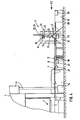
- the output area of the work pieces 17, which are led out of the work area 2 of the press 1, is formed by a drive 5 for a transfer device 6.
- the workpieces removed from the press arrive at a feed conveyor 8, which is formed from a roller conveyor with rollers driven by motor 22 or corresponding conveyor belts, via a finished part conveyor 7, which is driven by means of a motor-gear unit 21 or by ram drive of the press and the workpieces transported into the swivel range of the swivel device 10.
- the swiveling device essentially consists of a frame, in the upper area of which swivel arms 11 are pivotably or rotatably mounted about a pivot point for erecting the incoming workpieces.
- the swivel arms are driven clockwise in the observer's view via the drive motor 23, which is controlled by a signal.
- the drive motor 23 which is controlled by a signal.
- passages are left free for the movement of the swivel arms.
- the workpieces pivoted into the vertical are removed from the swivel arms by gripping elements 12, for example by suction elements working with controlled negative pressure.
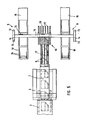
- the gripping elements are located on a carriage which can be moved perpendicularly to the previous conveying direction by a motor-gear unit 24 and which is essentially formed from a cross slide 16 and, if necessary, components to be described later and can be designed differently according to its different tasks.
- the cross slide is slidably mounted on a cross member 15, which is part of a portal 9, which consists of uprights 13 and upper chords 14.
- the cross slide carries suction elements at its two end areas, so that when the cross slide stops moving, one end area with a workpiece is located in a storage area, while the other end area is in the area of the pivoting device for gripping a subsequent workpiece. After it has been grasped and the workpiece conveyed into the storage area has been deposited, this is guided as a result of the opposite movement of the cross slide into a second storage area and is deposited here, while another workpiece is gripped by the gripping elements of the end region of the cross slide mentioned above.
- the storage areas are located on both sides and in parallel alignment to the first workpiece conveying direction and are each formed from a chain conveyor 31, which has not shown but known chain links with chain hangers 32 and conveys the detected workpieces via conveyor and deflection rollers 33, e.g. to the first surface treatment station or by containers 19 placed on a ramp 19 and above them running container conveyors 20 in the manner of transport frames with pick-up strips 26 for spaced storage of the workpieces.
- the chain conveyor is driven step by step via the motor 34, and the container conveyor is driven step by step via the drive unit 25.
- the containers 18 are already at the level of the workpiece 17 pivoted into the vertical by the swivel device 10. This is gripped by the gripping elements 12 of the cross slide 16 for movement in the direction perpendicular to the plane of the drawing. 1 shows the curvature of the vertically arranged workpieces on the cross slide and in the container which is kept open on the side.
- F ig. 2 shows, inter alia, the storage devices extending parallel on both sides to the conveyors 7 and 8, such as containers 18 and chain conveyors 31 for storing, receiving, hanging and the like.
- the workpieces are oriented in such a way as to come from the press tool that they are transported with the door uprights upwards, i.e. in the position of use, after being erected.
- Position 3 refers to gripper rails for transporting the workpieces between the press stages and, if necessary, for dispensing the workpieces.
- Fig. 3 shows the vertical arrangement of two workpieces 17, one of which is for storage in the container 18, another is still in the pivoting device 10.
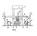
- Fig. 4 refers to a further embodiment shown in this and in Figs. 5 and 6 with floor-level containers Conveyors 20 and for inserting the workpieces from above into the container cross slide 16.
- the workpieces 17 are pivoted into a position above the container 18 and quenched.
- the workpieces 17 are conveyed in the direction of travel, this expression relating to the installation position on the vehicle.
- the workpieces are inserted into the container 18 from above.
- the workpieces stored in these indicate the curvature and thus their storage position.
- the cross slide 16 is motor-driven in the longitudinal extent of the cross member 15.
- a left and a right lowering spar 29, 30 are assigned to the end regions of the cross slide, and their height can be adjusted in height via the drive unit shown in FIG. 4 for inserting the workpieces into the containers from above.
- the gripping elements 12 on the cross slide 16 or on the lowering bars 29, 30 grip the workpieces 17 on the swiveling device 10 from the side, so that there is no obstruction by the gripping and moving elements when being put down.
- FIG. 7 shows a turner 35 that can be rotated by the motor 36 in order to swap the workpieces 17 lying on the side before being accessed by the pivoting arms 11.
Landscapes
- Engineering & Computer Science (AREA)
- Mechanical Engineering (AREA)
- Specific Conveyance Elements (AREA)
Applications Claiming Priority (2)
| Application Number | Priority Date | Filing Date | Title |
|---|---|---|---|
| DE3236145 | 1982-09-29 | ||
| DE19823236145 DE3236145A1 (de) | 1982-09-29 | 1982-09-29 | Einrichtung zum ablegen von werkstuecken nach der letzten in einem pressenwerkzeug erfolgten bearbeitungstufe |
Publications (3)
| Publication Number | Publication Date |
|---|---|
| EP0104569A2 true EP0104569A2 (fr) | 1984-04-04 |
| EP0104569A3 EP0104569A3 (en) | 1984-07-04 |
| EP0104569B1 EP0104569B1 (fr) | 1987-07-01 |
Family
ID=6174516
Family Applications (1)
| Application Number | Title | Priority Date | Filing Date |
|---|---|---|---|
| EP83109242A Expired EP0104569B1 (fr) | 1982-09-29 | 1983-09-19 | Dispositif destiné à déposer des pièces à travailler après le dernier degré d'usinage dans une presse |
Country Status (2)
| Country | Link |
|---|---|
| EP (1) | EP0104569B1 (fr) |
| DE (2) | DE3236145A1 (fr) |
Cited By (5)
| Publication number | Priority date | Publication date | Assignee | Title |
|---|---|---|---|---|
| FR2615167A1 (fr) * | 1987-05-11 | 1988-11-18 | Peugeot | Installation pour le rangement dans des conteneurs de pieces de vehicules automobiles |
| FR2783730A1 (fr) * | 1998-09-28 | 2000-03-31 | Mueller Weingarten Maschf | Dispositif pour le transport de pieces |
| DE19850964C2 (de) * | 1998-09-28 | 2003-03-27 | Mueller Weingarten Maschf | Einrichtung zum Transport von Werkstücken |
| CN104889283A (zh) * | 2015-05-17 | 2015-09-09 | 合肥长城制冷科技有限公司 | 一种中速冲床有序接翅片装置 |
| CN110355288A (zh) * | 2019-07-22 | 2019-10-22 | 无锡蓝力智能装备有限公司 | 板式换热器片数控精密成形成套装备 |
Families Citing this family (3)
| Publication number | Priority date | Publication date | Assignee | Title |
|---|---|---|---|---|
| JPS59147728A (ja) * | 1983-02-15 | 1984-08-24 | Komatsu Ltd | オ−トパレタイジング装置 |
| DE3416277A1 (de) * | 1984-05-03 | 1985-11-07 | Karl 6096 Raunheim Gerlach | Vorrichtung zum stapeln duennwandiger formteile |
| ES2038475T3 (es) * | 1989-10-18 | 1993-07-16 | Maschinenfabrik Muller-Weingarten Ag | Bandeja para partes de piezas en prensas escalonadas. |
Family Cites Families (7)
| Publication number | Priority date | Publication date | Assignee | Title |
|---|---|---|---|---|
| US2392032A (en) * | 1944-02-10 | 1946-01-01 | Caspers Tin Plate Company | Stripping and stacking apparatus and method |
| US2685359A (en) * | 1947-12-03 | 1954-08-03 | United States Steel Corp | Method of handling and assorting sheets |
| US3178041A (en) * | 1961-10-23 | 1965-04-13 | Libbey Owens Ford Glass Co | Sheet handling apparatus |
| DE1756061B1 (de) * | 1968-03-28 | 1970-08-20 | Ziegelei Appbau Gmbh | Anlage zum Stapeln von in einer Buendelvorrichtung zu Paketen gebuendelten Dachziegeln |
| DE1943125C3 (de) * | 1969-08-25 | 1975-10-16 | Braas & Co Gmbh, 6000 Frankfurt | Vorrichtung zum Stapeln von flachen Formkörpern in Hochkantstellung, insbesondere von Betondachsteinen |
| US4178122A (en) * | 1978-03-29 | 1979-12-11 | Abrahamson Daniel P | Method and apparatus for cubing brick |
| DE2825512B1 (de) * | 1978-06-10 | 1979-10-31 | Lingl Anlagenbau | Vorrichtung zum paarweisen Aufstellen von Strangdachziegeln zum Bilden von Setzreihen |
-
1982
- 1982-09-29 DE DE19823236145 patent/DE3236145A1/de not_active Withdrawn
-
1983
- 1983-09-19 EP EP83109242A patent/EP0104569B1/fr not_active Expired
- 1983-09-19 DE DE8383109242T patent/DE3372258D1/de not_active Expired
Cited By (5)
| Publication number | Priority date | Publication date | Assignee | Title |
|---|---|---|---|---|
| FR2615167A1 (fr) * | 1987-05-11 | 1988-11-18 | Peugeot | Installation pour le rangement dans des conteneurs de pieces de vehicules automobiles |
| FR2783730A1 (fr) * | 1998-09-28 | 2000-03-31 | Mueller Weingarten Maschf | Dispositif pour le transport de pieces |
| DE19850964C2 (de) * | 1998-09-28 | 2003-03-27 | Mueller Weingarten Maschf | Einrichtung zum Transport von Werkstücken |
| CN104889283A (zh) * | 2015-05-17 | 2015-09-09 | 合肥长城制冷科技有限公司 | 一种中速冲床有序接翅片装置 |
| CN110355288A (zh) * | 2019-07-22 | 2019-10-22 | 无锡蓝力智能装备有限公司 | 板式换热器片数控精密成形成套装备 |
Also Published As
| Publication number | Publication date |
|---|---|
| DE3372258D1 (en) | 1987-08-06 |
| EP0104569A3 (en) | 1984-07-04 |
| EP0104569B1 (fr) | 1987-07-01 |
| DE3236145A1 (de) | 1984-03-29 |
Similar Documents
| Publication | Publication Date | Title |
|---|---|---|
| DE69304356T2 (de) | Postvorrichtung | |
| DE2631942A1 (de) | Depalettierungsvorrichtung | |
| DE4203118A1 (de) | Vorrichtung zum ergreifen und transportieren von stapeln flacher gegenstaende | |
| EP0312498B1 (fr) | Méthode de transport de plaques | |
| DE2118523C3 (de) | Vorrichtung zum Bündeln von langgestrecktem Gut | |
| DE19636470A1 (de) | Vorrichtung zum Handhaben von Glasscheiben | |
| DE2852954C2 (de) | Verfahren zum Palettieren von offenen Behältern und Vorrichtung zu dessen Durchführung | |
| DE4205923C2 (de) | Vorrichtung zum Abstapeln von Schalen oder schalenähnlichen Gegenständen, insbesondere Geschirrschalen | |
| EP0104569B1 (fr) | Dispositif destiné à déposer des pièces à travailler après le dernier degré d'usinage dans une presse | |
| DE4213301C2 (de) | Vorrichtung und Verfahren zur Entnahme von oben offenen gestapelten Kästen | |
| EP0132635A2 (fr) | Dispositif de chargement pour objets élongés | |
| DE3502359C2 (de) | Einrichtung zum Transport stapelbarer flacher Teile, insbesondere Kraftfahrzeug-Karosserieteile | |
| DE2106091C3 (de) | Vorrichtung zum verschachtelten, lageweisen Stapeln von profiliertem Walzgut | |
| EP0256403B1 (fr) | Procédé de transfert automatique de muselets en fil métallique pour bouteilles à champagne d'une station d'usinage à un empilage ou d'un empilage à une station d'usinage ultérieure et dispositif pour la mise en oeuvre de ce procédé | |
| EP0426694B1 (fr) | Dispositif pour empiler des pieces preformees | |
| DE3527746C2 (fr) | ||
| EP0210172B1 (fr) | Dispositif pour empiler des pieces a paroi mince | |
| DE3119418C2 (de) | Übergabevorrichtung beim Transport von Gegenständen zum Aufbringen von Überzügen | |
| DE2435671C3 (de) | Verfahren und Vorrichtung zum Handhaben und Lagern von länglichen Gegenständen | |
| DE3712838C2 (fr) | ||
| DE2727938A1 (de) | Foerdersystem mit rollgang und querfoerdereinrichtung | |
| DE3844564C2 (fr) | ||
| DE3932391C1 (en) | Endless chain conveyor system - has frames connected to chain to hold workpieces standing on edge | |
| DE3151208C2 (de) | Vorrichtung zum Entnehmen ferromagnetischer Blechplatinen aus Blechbearbeitungsmaschinen | |
| DE8501637U1 (de) | Gerät zum Stapeln von einzeln ankommenden Gegenständen, z. B. Werkstücke, in aufeinanderliegenden, jeweils mehrere Gegenstände enthaltenden Gegenstandslagen |
Legal Events
| Date | Code | Title | Description |
|---|---|---|---|
| PUAI | Public reference made under article 153(3) epc to a published international application that has entered the european phase |
Free format text: ORIGINAL CODE: 0009012 |
|
| AK | Designated contracting states |
Designated state(s): DE FR GB IT SE |
|
| PUAL | Search report despatched |
Free format text: ORIGINAL CODE: 0009013 |
|
| AK | Designated contracting states |
Designated state(s): DE FR GB IT SE |
|
| 17P | Request for examination filed |
Effective date: 19841206 |
|
| 17Q | First examination report despatched |
Effective date: 19860219 |
|
| GRAA | (expected) grant |
Free format text: ORIGINAL CODE: 0009210 |
|
| AK | Designated contracting states |
Kind code of ref document: B1 Designated state(s): DE FR GB IT SE |
|
| ET | Fr: translation filed | ||
| REF | Corresponds to: |
Ref document number: 3372258 Country of ref document: DE Date of ref document: 19870806 |
|
| ITF | It: translation for a ep patent filed | ||
| PLBE | No opposition filed within time limit |
Free format text: ORIGINAL CODE: 0009261 |
|
| STAA | Information on the status of an ep patent application or granted ep patent |
Free format text: STATUS: NO OPPOSITION FILED WITHIN TIME LIMIT |
|
| 26N | No opposition filed | ||
| PG25 | Lapsed in a contracting state [announced via postgrant information from national office to epo] |
Ref country code: GB Effective date: 19880919 |
|
| PG25 | Lapsed in a contracting state [announced via postgrant information from national office to epo] |
Ref country code: SE Effective date: 19880920 |
|
| PG25 | Lapsed in a contracting state [announced via postgrant information from national office to epo] |
Ref country code: FR Free format text: LAPSE BECAUSE OF NON-PAYMENT OF DUE FEES Effective date: 19890531 |
|
| GBPC | Gb: european patent ceased through non-payment of renewal fee | ||
| PG25 | Lapsed in a contracting state [announced via postgrant information from national office to epo] |
Ref country code: DE Effective date: 19890601 |
|
| REG | Reference to a national code |
Ref country code: FR Ref legal event code: ST |
|
| EUG | Se: european patent has lapsed |
Ref document number: 83109242.4 Effective date: 19890712 |