EP0104642A1 - Belastung anzeigender Flansch - Google Patents
Belastung anzeigender Flansch Download PDFInfo
- Publication number
- EP0104642A1 EP0104642A1 EP83109591A EP83109591A EP0104642A1 EP 0104642 A1 EP0104642 A1 EP 0104642A1 EP 83109591 A EP83109591 A EP 83109591A EP 83109591 A EP83109591 A EP 83109591A EP 0104642 A1 EP0104642 A1 EP 0104642A1
- Authority
- EP
- European Patent Office
- Prior art keywords
- flange
- gauge
- workpiece
- load indicating
- face
- Prior art date
- Legal status (The legal status is an assumption and is not a legal conclusion. Google has not performed a legal analysis and makes no representation as to the accuracy of the status listed.)
- Withdrawn
Links
- 230000002093 peripheral effect Effects 0.000 claims abstract description 31
- 230000036316 preload Effects 0.000 description 3
- 230000037390 scarring Effects 0.000 description 3
- 230000000295 complement effect Effects 0.000 description 2
- 238000010276 construction Methods 0.000 description 2
- 239000002184 metal Substances 0.000 description 2
- 125000004122 cyclic group Chemical group 0.000 description 1
- 238000010438 heat treatment Methods 0.000 description 1
- 238000009434 installation Methods 0.000 description 1
- 238000000034 method Methods 0.000 description 1
- 230000007704 transition Effects 0.000 description 1
Images

Classifications
-
- F—MECHANICAL ENGINEERING; LIGHTING; HEATING; WEAPONS; BLASTING
- F16—ENGINEERING ELEMENTS AND UNITS; GENERAL MEASURES FOR PRODUCING AND MAINTAINING EFFECTIVE FUNCTIONING OF MACHINES OR INSTALLATIONS; THERMAL INSULATION IN GENERAL
- F16B—DEVICES FOR FASTENING OR SECURING CONSTRUCTIONAL ELEMENTS OR MACHINE PARTS TOGETHER, e.g. NAILS, BOLTS, CIRCLIPS, CLAMPS, CLIPS OR WEDGES; JOINTS OR JOINTING
- F16B31/00—Screwed connections specially modified in view of tensile load; Break-bolts
- F16B31/02—Screwed connections specially modified in view of tensile load; Break-bolts for indicating the attainment of a particular tensile load or limiting tensile load
- F16B31/024—Screwed connections specially modified in view of tensile load; Break-bolts for indicating the attainment of a particular tensile load or limiting tensile load with the bottom of the nut or of the head of the bolt having gaps which close as the bolt tension increases, e.g. with lips or with a load-indicating flange
Definitions
- Bolts or nuts have previously been provided with an extending flange which has a wavy bearing surface, including crests and troughs, the crests engaging a workpiece upon initial installation, and then upon tightening of the threaded fastener the troughs of the wavy surface are pulled into engagement with the working surface of the workpiece. When this occurs, it indicates that the threaded fastener has been stressed to a predetermined proper amount.
- a load indicating fastener is shown in U.S. patent 4,293,256. This may be utilized to establish a predetermined preload on the fastener, the fastener being subject to cyclic or vibrational forces which might otherwise tend to loosen the threaded fastener unless it was properly stressed.
- the subjecting of the threaded fastener to a varying load can cause fatigue failure; hence, the endurance, strength and fatigue life of the fastener are considerably improved by applying a precise preload to the fastener.
- Torque wrenches or other torque measuring devices have been previously used to attempt to determine the preload on the fastener. Such methods are inaccurate because many factors affect the resistance encountered by a torque wrench, including type and degree of heat treatment, the type and surface finish of the threads on both threaded fasteners, and the coefficient of friction between the two threaded fasteners as ' -well as between the fastener and the working surface of the workpiece.
- a known load indicating washer was one which had on a first face thereof a series of dimples pressed-therein so that on the opposite face a series of complementary projections were provided. These projections were about midway of the radial extent of the washer and when the washer and threaded fastener combination was properly tightened against the working surface, the projections in the washer flattened out completely so that even a thin gauge could not be inserted at any place around the periphery of the washer between the washer and the working surface, thus determining the tightness of the threaded fastener.
- U.S. patent 4,281,699 illustrated another form of a load indicating flange on a threaded fastener wherein the flange was initially planar except for biting teeth and, when tightened, was.then deflected into a wavy surface by buttresses which strengthened the flange intermediate the locking teeth.
- the problem to be solved is how to provide a load indicating flange for a threaded fastener wherein the amount of stress or load on.the threaded fastener may readily be determined.
- a load indicating annular flange for cooperation with a first threaded fastener interengageable with a second threaded fastener, said flange having a first axially directed face relative to the axis of the' first threaded fastener, said first face having crest means adapted to engage and transmit an axial load force to a cooperable surface upon the fasteners being tightened onto a workpiece, the flange having a least one trough portion in said first face and having portions resiliently deformable to have the trough portion movable toward the cooperable surface upon tightening of the two threaded fasteners onto a workpiece, characterized in that at least one gauge opening defined by a gauging surface is provided in said flange near said trough portion, said gauge opening having a predetermined thickness dimension parallel to said axis in the order of 0.005 to 0.030 inch to preclude entrance thereinto of a gauge of a predetermined thickness when the threaded fasteners have been properly
- a load indicating annular-flange for cooperation with a first threaded fastener interengageable with a second threaded fastener, said flange having a first axially directed face relative to the axis of the first threaded fastener, said first face having crest means adapted to engage and transmit an axial load force to a cooperable surface upon the fasteners being tightened onto a workpiece, the flange having at least one trough portion in said first face and having portions resiliently deformable to have the trough portion movable toward the cooperable surface upon tightening of the two threaded fasteners onto a workpiece, characterized in that a narrow band peripheral bearing surface is provided on the radially outer portion of said flange first face, said peripheral bearing surface including said crest means and being a surface in all peripheral parts thereof substantially perpendicular to said axis along each radii to said axis.
- an object of the invention is to provide a gauge opening in a flange surface of a load indicating flange to enable a person to determine the proper place to attempt to insert a gauge.
- Another object of the invention is to provide a peripheral bearing surface on a load indicating flange which results in a minimum scarring of the surface of the workpiece.
- a further object of the invention is to provide a gauge opening in a load indicating flange to accept a relatively thick gauge.
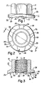
- FIGS. 1, 2, and 3 illustrate a load indicating flange 11 which is adapted for cooperation with a threaded fastener 12.
- This threaded fastener may be a nut 12 as shown in FIGS. 1-3, or maybe a bolt 13 as shown in FIGS. 4 and 5.
- this invention is illustrated as applied to threaded fasteners, it may also be applied to non-threaded fasteners, for example, to Huck bolts.
- the load indicating flange is an annular flange, and may be a completely separate member for cooperation with the nut or bolt, it is shown as being unitary with the nut 12 or bolt 13.
- the nut 12 has a body 16 which includes wrench pads 17, shown here as six in number, for a hexagonal surface to accept a tool for tightening or loosening the nut 12.
- This is an example of a surface which in cross section is a polygon to accept the tool.
- a hexagonal socket head in a cap screw would be another form of a wrench pad.
- the nut has an axis 18 and a hollow interior with a female thread 19 of a suitable form.
- the nut body has a flat, annular bottom surface 20 coaxial with the axis 18, which bottom surface is adapted to cooperate with a work surface 21 of a workpiece 22 (see FIG. 5).
- the flange 11 has a first or lower face 25 which is an axially directed face relative to the axis 18.
- the flange further has a second opposite face 24.
- This first face 25 has a plurality of crests 26 and a plurality of troughs 27 therebetween. There may be two or more such crests 26, and preferably three crests and three troughs are provided on the first face 25, establishing a wavy surface 28.
- the three crests provide a three-point contact relative to a cooperable surface when the threaded fastener is initially placed on a work surface of a workpiece. These three crests are adapted to engage and to transmit an axial load force to such cooperable surface, such as the work surface 21 of FIG. 5.
- the flange 11 has a plurality of resiliently deformable portions, and in FIGS. 1-3 this takes the form of a spring section 29, which lies generally radially outboard of the body 16 and also radially outboard of an annular groove 30 which lies generally at the periphery of the body 16.
- This annular groove helps to define the precise radial length of the spring section 29 and to more precisely define the load force required to axially deform such spring sections 29.
- a gauge surface is provided in the nut 12, and more specifically it is in the flange 11.
- This gauge surface takes the form of gauge grooves 33 extending axially into the wavy surface 28 by a predetermined thickness dimension in the order of 0.005 to 0.030 inch.
- Each gauge groove is bounded by rounded shoulders 34, which shoulders extend to the trough portions 27. These shoulders are at at least a 45-degree angle relative to the wavy surface 28, and preferably are close to a right angle.
- the grooves are bounded by the shoulders 34, which may be parallel to each other but are shown in FIG. 2 as being radial lines.
- Such shoulders extend from the outer radial periphery of the face 25 to the annular groove 30, and are further defined by the groove face 35 (see FIG. 3), which is normal to the axis 18, and a tapered face 36 extending from the inner end of the groove face 35 to merge into the wavy surface 28 at the outer periphery of the annular groove 30. This maintains the integrity of this annular groove, to maintain the correctness of the spring calibration on the amount of tensile stress required to deform the spring section 29.
- the gauge groove prefferably with relatively well-defined shoulders which result in a well-defined gauge opening that is easily located visually. Further, with such structure, abutment or seating surfaces are located immediately adjacent to the gauge opening to accurately establish its height.
- the amplitude of the wave is selected so that the gauge surface 33 is spaced a predetermined minimum distance from the associated workpiece 22 when the annular bottom or seating surface 20 is seated against the workpiece.
- a narrow band peripheral bearing surface 39 is provided on the radially outer portion of the flange first face 25.
- This peripheral surface is perpendicular to the axis 18 as the surface follows the elevation of the wavy surface 28.
- this narrow band peripheral bearing surface is a surface'which is perpendicular to the axis'18 along each radius to the axis 18 around the peripheral extent of this peripheral bearing surface 39.
- the wavy surface 28 further includes an abutment surface 40, which is a curved surface as shown in FIGS. 2 and 3.
- the crest areas 26 are shown stippled to illustrate the relatively small areas of the wavy surface 28 which initially touch the cooperable surface such as the work surface 21, before the threaded fasteners are tightened.
- FIGS. 4, 5, and 6 illustrate the flange 11 as being incorporated in the head of a bolt 13.
- the flange is shown as adapted to be cooperable with a surface 44, shown as a work surface 44 on the workpiece 22.
- FIGS. 4 to 6 show the bolt 13 in the initially installed but untightened condition
- FIG. 5 shows the bolt 13 tightened on the nut 45.
- the load indicating flange 11 operates in the same manner, whether it is a separate part cooperating with the head of a bolt or is unitary with the nut or bolt, as shown in FIGS. 1 and 4, respectively.
- the load indicating flange 11 will be described in connection with FIGS. 4, 5, and 6, since these figures show the cooperable surface, such as the work surface 44, of a workpiece 22, which work surface 44 is normal to the axis 18.
- the load indicating flange is shown as being integral with the bolt 13, which is a threaded fastener cooperable with a complementary threaded fastener, namely, the nut 45.
- the bolt 13 When the bolt 13 is first placed in the aperture 46 of the workpiece 22, it will be the three crests 26 which engage the work surface 44. As shown in FIG. 2, these crests provide relatively small areas or portions of contact on the narrow band peripheral bearing surface 39. In FI G. 2, these are stippled to indicate the small surface area of contact.
- the flat annular bottom seating surface 20 When the bolt and nut have been properly tightened onto the workpiece 22, the flat annular bottom seating surface 20 will be pulled into contact with the work surface 44. This is not visible from the exterior of the bolt or nut, so this is not a good indication of the tightness of the bolt and nut.
- the abutment or seating surface 40 included in the troughs 27 will be pulled into engagement with the work surface 44.
- the abutment surface 40 was previously a curved surface but, as shown in FIG. 5, has been deformed to lie in a plane normal to the axis 18 and to engage the work surface 44.
- the gauge grooves 33 are now usable to gauge the tightness of the threaded fasteners 13 and 45.
- the gauge groove 33 may have a depth parallel to axis. 18 of '0.010 inches. A gauge of that thickness, or perhaps slightly thicker at 0.0105 inches may be used to gauge the tightness of the fasteners. If it enters the gauge groove 33 the fasteners are not sufficiently tightened, and if it does not enter the groove, they are sufficiently tightened. If the threaded fasteners are tightened properly, the abutment surface 40 will be pulled flat into engagement with the work surface 44, as illustrated in FIG. 6.
- the present invention provides a readily visible place to apply the gauge, and since the abutment surfaces 40 are on each side of the gauge groove 33 and immediately adjacent thereto, this is a definite stop abutment for the flange 11 whether the fastener is tightened with a manually applied wrench or power-operated torque wrench.
- the gauge groove 33 is relatively narrow in peripheral extent, so that when the abutment surfaces 40 on both sides thereof engage the work surface 44, the gauge groove face 35 is positively supported and there is no tendency for this gauge groove face 35 to crush toward the work surface 44.
- An additional feature of the invention is the provision of the narrow band peripheral bearing surface 39.
- the load indicating flange 11 is on the bolt 13, as shown in FIGS. 4 and 5, the"workman is supposed to tighten the nut 45 rather than the bolt 13.
- the manufacturer of the bolts 13 has no real control over the workmen in the field, and such workmen will often tighten the bolt 13 rather than the nut 45.
- only one set of wrench pads is readily accessible to the power-operated torque wrench, and this may be the bolt head, even though this bolt is the one that has the load indicating flange 11.
- the narrow band peripheral bearing surface 39 is initially flat against the work surface 44, as shown by the stippled areas in FIG. 2.
- the transition between the narrow band peripheral bearing surface 39 and the curved abutment surface 40 is not a sharp corner, but is rather at a small radius, e.g., 1/32 inch, which again minimizes any scarring of the work surface 44 even though the flange is resiliently deformed as shown in FIG. 5.
- the gauge grooves are provided near the depth of the troughs 27 and, as shown, are directly at the depths of such troughs.
- the flange 11 is of substantially uniform thickness, so that the phase of the wave on the first face 25 is essentially in phase with the wave on the opposite face 24.
- the narrow band peripheral bearing surface 39 is circumferentially interrupted by the gauge grooves 33, and hence this peripheral bearing surface extends from one gauge groove across a crest to the next adjacent gauge groove.
Landscapes
- Engineering & Computer Science (AREA)
- General Engineering & Computer Science (AREA)
- Mechanical Engineering (AREA)
- Force Measurement Appropriate To Specific Purposes (AREA)
- Level Indicators Using A Float (AREA)
- Confectionery (AREA)
- Load-Engaging Elements For Cranes (AREA)
- Bolts, Nuts, And Washers (AREA)
Applications Claiming Priority (2)
| Application Number | Priority Date | Filing Date | Title |
|---|---|---|---|
| US06/423,861 US4498825A (en) | 1982-09-27 | 1982-09-27 | Load indicating flange |
| US423861 | 1995-04-18 |
Publications (1)
| Publication Number | Publication Date |
|---|---|
| EP0104642A1 true EP0104642A1 (de) | 1984-04-04 |
Family
ID=23680471
Family Applications (1)
| Application Number | Title | Priority Date | Filing Date |
|---|---|---|---|
| EP83109591A Withdrawn EP0104642A1 (de) | 1982-09-27 | 1983-09-27 | Belastung anzeigender Flansch |
Country Status (4)
| Country | Link |
|---|---|
| US (1) | US4498825A (de) |
| EP (1) | EP0104642A1 (de) |
| JP (1) | JPS5980516A (de) |
| AU (1) | AU1931983A (de) |
Cited By (3)
| Publication number | Priority date | Publication date | Assignee | Title |
|---|---|---|---|---|
| WO2012076360A1 (de) * | 2010-12-06 | 2012-06-14 | Ejot Gmbh & Co. Kg | Schraube mit einem schraubenkopf, einem schraubenschaft und einem konischen, gewellten flansch |
| ES2431895R1 (es) * | 2012-05-28 | 2014-02-04 | Guillermo Petri Larrea | Sistema para mantenimiento de la precarga de uniones de piezas de tipo embridado y procedimiento asociado para montar una unión. |
| RU2574803C2 (ru) * | 2010-12-06 | 2016-02-10 | Эйот Гмбх Унд Ко. Кг | Винт, включающий в себя головку винта, стержень винта и конический волнистый фланец |
Families Citing this family (28)
| Publication number | Priority date | Publication date | Assignee | Title |
|---|---|---|---|---|
| US4559830A (en) * | 1984-03-29 | 1985-12-24 | Raymond Plummer | Testing device for fasteners |
| JPS6324412U (de) * | 1986-07-30 | 1988-02-18 | ||
| US4812095A (en) * | 1987-02-24 | 1989-03-14 | Emhart Industries, Inc. | Threaded fastener |
| US5090854A (en) * | 1991-03-06 | 1992-02-25 | Artifex Ltd. | Self locking nut |
| US5533850A (en) * | 1993-12-21 | 1996-07-09 | Nissan Motor Co., Ltd. | Welding nut |
| US5746556A (en) * | 1995-03-13 | 1998-05-05 | Kabushiki Kaisha Youma Kohboh | Anchor unit with expansive anchor member expanded by utilizing turning force of bolt |
| US5861557A (en) * | 1997-11-07 | 1999-01-19 | Sahs; Stephen | Cable yield indicator for earthquake restrainer cables |
| US6152665A (en) * | 1999-08-20 | 2000-11-28 | Applied Bolting Technology Products, Inc. | Direct tension indicating washers |
| US6425718B1 (en) | 2000-07-11 | 2002-07-30 | Applied Bolting Technology Products Inc. | Direct multi-tension indicating washer having bumps of a first and second height |
| US20030007844A1 (en) * | 2001-05-31 | 2003-01-09 | Terry Sydney Lee | Anti-loosening nut for threaded fasteners |
| US6749386B2 (en) | 2001-08-20 | 2004-06-15 | Maclean-Fogg Company | Locking fastener assembly |
| US20060051182A1 (en) * | 2001-08-20 | 2006-03-09 | Gerard Jakuszeski | Fastener assembly |
| US7334975B2 (en) * | 2001-08-20 | 2008-02-26 | Maclean-Fogg Company | Fastener assembly |
| US6709211B1 (en) | 2002-07-03 | 2004-03-23 | Chief Industries, Inc. | Girt or purlin retainer and method of using same |
| US20040234358A1 (en) * | 2003-05-21 | 2004-11-25 | Newfrey Llc | Fastener assembly and method employing a flanged metal nut with a metal cup washer rotatably mounted thereon |
| US20040247409A1 (en) * | 2003-06-03 | 2004-12-09 | Chih-Chung Chiang | Nut member with tightness-indicating protrusions |
| US7465135B2 (en) | 2003-11-14 | 2008-12-16 | Maclean-Fogg Company | U-Nut fastening assembly |
| US20080166200A1 (en) * | 2007-01-10 | 2008-07-10 | Mccoy Bolt Works, Inc. | Device for establishing desired minimum preload condition obtained in a fastener shank |
| US8382409B2 (en) * | 2009-05-19 | 2013-02-26 | Applied Bolting Technology Products, Inc. | Direct tension multi-color indicating washers |
| DE102010030408A1 (de) * | 2010-06-23 | 2011-12-29 | Hilti Aktiengesellschaft | Schraube und Verfahren zum Identifizieren der Schraube |
| DE202011111010U1 (de) * | 2011-01-03 | 2018-05-28 | Wolfgang B. Thörner | Polklemme |
| JP5533776B2 (ja) * | 2011-04-26 | 2014-06-25 | 日本精工株式会社 | 一対のフランジ部とフランジ付き六角ボルト組合せ体 |
| US8974164B2 (en) * | 2012-06-26 | 2015-03-10 | Newfrey Llc | Plastic high heat fastener |
| TWI495800B (zh) * | 2013-03-06 | 2015-08-11 | Kabo Tool Co | A screw with a locking force |
| US10156251B2 (en) * | 2016-11-04 | 2018-12-18 | Ford Global Technologies, Llc | Recessed spring washer flow drill screw |
| JP6260843B1 (ja) * | 2017-03-14 | 2018-01-17 | 忠 井上 | 緩まないロックナット |
| CN110107574B (zh) * | 2019-06-05 | 2024-04-09 | 华域视觉科技(上海)有限公司 | 一种紧固组件 |
| US12055173B2 (en) | 2021-06-15 | 2024-08-06 | Lockheed Martin Corporation | Flexible head fasteners |
Citations (7)
| Publication number | Priority date | Publication date | Assignee | Title |
|---|---|---|---|---|
| US4020734A (en) * | 1975-11-26 | 1977-05-03 | Star Expansion Industries Corporation | Tension indicator for fastener means |
| US4220188A (en) * | 1978-07-10 | 1980-09-02 | Russell, Burdsall & Ward Corporation | Locking fastener |
| US4223711A (en) * | 1978-07-03 | 1980-09-23 | Russell, Burdsall & Ward Corporation | Self-locking fastener |
| US4281699A (en) * | 1979-04-20 | 1981-08-04 | Maclean-Fogg Company | Locking fastener with resilient and rigid flange segments |
| US4290469A (en) * | 1979-09-04 | 1981-09-22 | Kishu Neji Co., Ltd. | Self-locking nut-type or bolt-type fastening device |
| US4293256A (en) * | 1979-11-09 | 1981-10-06 | The Lamson & Sessions Co. | Load indicating fastener |
| AT370217B (de) * | 1981-04-06 | 1983-03-10 | Fink Hans | Befestigungselement |
Family Cites Families (4)
| Publication number | Priority date | Publication date | Assignee | Title |
|---|---|---|---|---|
| US1923647A (en) * | 1931-03-18 | 1933-08-22 | Howard H Osborn | Lock bolt, nut, or screw |
| FR1210956A (fr) * | 1958-10-11 | 1960-03-11 | Kellermann Fa Rudolf | Perfectionnements apportés aux dispositifs évitant un serrage excessif des boulonsà chapeau et des écrous |
| NL169513C (nl) * | 1978-01-13 | 1982-07-16 | Nedschroef Octrooi Maats | Zelfborgend bevestigingselement respectievelijk een stempel voor het maken van dat element. |
| US4269248A (en) * | 1979-04-20 | 1981-05-26 | Maclean-Fogg Company | Fastener with flexible flange |
-
1982
- 1982-09-27 US US06/423,861 patent/US4498825A/en not_active Expired - Fee Related
-
1983
- 1983-09-21 AU AU19319/83A patent/AU1931983A/en not_active Abandoned
- 1983-09-27 EP EP83109591A patent/EP0104642A1/de not_active Withdrawn
- 1983-09-27 JP JP58179081A patent/JPS5980516A/ja active Pending
Patent Citations (7)
| Publication number | Priority date | Publication date | Assignee | Title |
|---|---|---|---|---|
| US4020734A (en) * | 1975-11-26 | 1977-05-03 | Star Expansion Industries Corporation | Tension indicator for fastener means |
| US4223711A (en) * | 1978-07-03 | 1980-09-23 | Russell, Burdsall & Ward Corporation | Self-locking fastener |
| US4220188A (en) * | 1978-07-10 | 1980-09-02 | Russell, Burdsall & Ward Corporation | Locking fastener |
| US4281699A (en) * | 1979-04-20 | 1981-08-04 | Maclean-Fogg Company | Locking fastener with resilient and rigid flange segments |
| US4290469A (en) * | 1979-09-04 | 1981-09-22 | Kishu Neji Co., Ltd. | Self-locking nut-type or bolt-type fastening device |
| US4293256A (en) * | 1979-11-09 | 1981-10-06 | The Lamson & Sessions Co. | Load indicating fastener |
| AT370217B (de) * | 1981-04-06 | 1983-03-10 | Fink Hans | Befestigungselement |
Cited By (6)
| Publication number | Priority date | Publication date | Assignee | Title |
|---|---|---|---|---|
| WO2012076360A1 (de) * | 2010-12-06 | 2012-06-14 | Ejot Gmbh & Co. Kg | Schraube mit einem schraubenkopf, einem schraubenschaft und einem konischen, gewellten flansch |
| CN103249956A (zh) * | 2010-12-06 | 2013-08-14 | 伊卓特有限两合公司 | 具有螺头、螺杆以及波浪圆锥形凸缘的螺钉 |
| CN103249956B (zh) * | 2010-12-06 | 2015-06-10 | 伊卓特有限两合公司 | 具有螺头、螺杆以及波浪圆锥形凸缘的螺钉 |
| US9109619B2 (en) | 2010-12-06 | 2015-08-18 | Ejot Gmbh & Co. Kg | Screw having a screw head, a screw shank and a corrugated conical flange |
| RU2574803C2 (ru) * | 2010-12-06 | 2016-02-10 | Эйот Гмбх Унд Ко. Кг | Винт, включающий в себя головку винта, стержень винта и конический волнистый фланец |
| ES2431895R1 (es) * | 2012-05-28 | 2014-02-04 | Guillermo Petri Larrea | Sistema para mantenimiento de la precarga de uniones de piezas de tipo embridado y procedimiento asociado para montar una unión. |
Also Published As
| Publication number | Publication date |
|---|---|
| AU1931983A (en) | 1984-04-05 |
| JPS5980516A (ja) | 1984-05-10 |
| US4498825A (en) | 1985-02-12 |
Similar Documents
| Publication | Publication Date | Title |
|---|---|---|
| US4498825A (en) | Load indicating flange | |
| US4020734A (en) | Tension indicator for fastener means | |
| US5282707A (en) | Fastening system for locking nut with torque indicating marks | |
| US5015132A (en) | Direct tension indicator washer | |
| EP1403535A1 (de) | Schraubenfestziehkonstruktion, schraubenglied und schraubenfestziehwerkzeug | |
| US4125051A (en) | Tamperproof fastener | |
| US3304109A (en) | Joint including tapered fastener | |
| US3135154A (en) | Locking and tension indicating washer nut device | |
| EP1092098B1 (de) | Schraubverbindungselement mit einer klemmlast | |
| US4223711A (en) | Self-locking fastener | |
| JP5185931B2 (ja) | 荷重指示式留め具および製造の方法 | |
| US5667346A (en) | Direct tension indicator washer | |
| US4705441A (en) | Self locking sheet metal screw | |
| US3926237A (en) | Self-locking vibration-proof lock washer and cooperating threaded fastener | |
| CA1136454A (en) | Load indicating fastener | |
| JPS6240564B2 (de) | ||
| US3460428A (en) | Threaded fastener with torque limiting drive portions | |
| US5226765A (en) | Load-indicating fastener | |
| US3311147A (en) | Preloaded nut | |
| US20190134787A1 (en) | Wrench for maximizing torque | |
| JP3441084B2 (ja) | 自動係止ファスナ | |
| US5722807A (en) | Clamp load indicator | |
| US3789726A (en) | Load-indicating means for a nut and bolt assembly | |
| US3534651A (en) | Preload indicating nut | |
| US4921380A (en) | Fastener assembly |
Legal Events
| Date | Code | Title | Description |
|---|---|---|---|
| PUAI | Public reference made under article 153(3) epc to a published international application that has entered the european phase |
Free format text: ORIGINAL CODE: 0009012 |
|
| AK | Designated contracting states |
Designated state(s): BE DE FR GB IT NL SE |
|
| STAA | Information on the status of an ep patent application or granted ep patent |
Free format text: STATUS: THE APPLICATION IS DEEMED TO BE WITHDRAWN |
|
| 18D | Application deemed to be withdrawn |
Effective date: 19841205 |
|
| RIN1 | Information on inventor provided before grant (corrected) |
Inventor name: CAPUANO, TERRY D. Inventor name: ZILS, JAMES A. Inventor name: PAMER, WALTER R. |