EP0104661A2 - Lichtstreuungszelle - Google Patents
Lichtstreuungszelle Download PDFInfo
- Publication number
- EP0104661A2 EP0104661A2 EP83109718A EP83109718A EP0104661A2 EP 0104661 A2 EP0104661 A2 EP 0104661A2 EP 83109718 A EP83109718 A EP 83109718A EP 83109718 A EP83109718 A EP 83109718A EP 0104661 A2 EP0104661 A2 EP 0104661A2
- Authority
- EP
- European Patent Office
- Prior art keywords
- window
- sample
- radiation
- scattering
- cavity
- Prior art date
- Legal status (The legal status is an assumption and is not a legal conclusion. Google has not performed a legal analysis and makes no representation as to the accuracy of the status listed.)
- Ceased
Links
Images
Classifications
-
- G—PHYSICS
- G01—MEASURING; TESTING
- G01N—INVESTIGATING OR ANALYSING MATERIALS BY DETERMINING THEIR CHEMICAL OR PHYSICAL PROPERTIES
- G01N21/00—Investigating or analysing materials by the use of optical means, i.e. using sub-millimetre waves, infrared, visible or ultraviolet light
- G01N21/01—Arrangements or apparatus for facilitating the optical investigation
- G01N21/03—Cuvette constructions
-
- G—PHYSICS
- G01—MEASURING; TESTING
- G01N—INVESTIGATING OR ANALYSING MATERIALS BY DETERMINING THEIR CHEMICAL OR PHYSICAL PROPERTIES
- G01N21/00—Investigating or analysing materials by the use of optical means, i.e. using sub-millimetre waves, infrared, visible or ultraviolet light
- G01N21/17—Systems in which incident light is modified in accordance with the properties of the material investigated
- G01N21/47—Scattering, i.e. diffuse reflection
- G01N21/49—Scattering, i.e. diffuse reflection within a body or fluid
- G01N21/51—Scattering, i.e. diffuse reflection within a body or fluid inside a container, e.g. in an ampoule
Definitions
- the present invention relates to scattering cells and, in particular, to cells designed to measure both relatively small scattering angles as well as large scattering angles.
- Particles disposed in a medium having a different index of refraction than the particles can scatter light.
- the intensity of the scattered light is a function of the wave length of the incident light, the size and concentration of the scattering particles, as well as the volume of the sample being irradiated.
- the scattering sample can transmit a direct and a scattered beam whose intensity ratio can be related to the Rayleigh factor to obtain an indication of molecular weight.
- a well known method of analyzing the scattered intensity of light is by a Zimm plot. By extrapolating this plot to zero concentration at zero scattering angle, an estimate can be made of the reciprocal of molecular weight.
- various slopes of the Zimm plot relate to the radius of gyration of the scattering particles. :n particular the second virial coefficient of the Zimm plot can be related to the non-ideality of the scattering particles, thereby characterizing the particles by their interaction with the medium and different surrounding particles.
- the slopes of the Zimm plot may be linear out to very large scattering angles. Therefore it is desirable under these circumstances to obtain a plot extending from very small to very large angles.
- Another class of useful data can be obtained from observing the frequency bandwidth or Doppler shifts caused by particle motion. This effect tends to broaden the line width of the spectrum transmitted from the scattering sample.
- these frequency effects can be evaluated to allow derivation of the diffusion coefficient of the particles.
- This coefficient bears a relation to the particles' size and shape and molecular weight.
- the diffusion coefficient measured in this fashion can vary as a function of the scattering angle.
- the manner in which this diffusion coefficient changes signifies the nature and number of the degrees of freedom of the particles. For very small scattering angles, the diffusion coefficient is related primarily to the translational degrees of freedom. Such information is very valuable for studying anisotropic particles. Other types of degrees of freedom may be revealed only at relatively large angles.
- a practical problem with obtaining accurate scattering measurements is accounting for extraneous particles in the medium.
- the clarification required to exclude such extraneous particles can be time consuming and expensive.
- An advance has been achieved with the advent of highly focused lasers which concentrate coherent light within an extremely small volume. The probability therefore of an extraneous particle entering within this small volume becomes rather small and its presence is obvious.
- Another practical problem is designing a sample cell so that light passing within its windows does not reflect back into the scattering sample. Such reflections can cause an undesirable illumination of the sample resulting in a background noise that degrades the accuracy of the measurement, expecially at very low angles.
- U.S. Patent 3,843,268 For overcoming the internal reflections within the window of a sample cell involves using relatively thick windows. These thick windows provide a relatively long optical path so that light internally reflected by the window has less of a tendency to return to the sample volume.
- the design of the exit windows in U.S.Patent 3,843,268 permits 180° back reflections at the air/glass interface allowing incident light to reenter the scattering volume.
- the scattering volume has incident beams in opposite direction with the reflected beam having an intensity of about 4% of the main beam.
- Another disadvantage with this type of system is that its use of relatively thick windows prevents measurements at relatively high scattering angles. Also the system does not attempt to increase the angular resolution for measurements at very low scattering angles.
- a scattering cell for containing a sample whose scattering properties upon irradiation can be measured by a detector.
- the cell includes a central body, an input window and a prismatic output window.
- the central body has an input and output side spanned by a sample cavity.
- the input window borders the sample cavity on the input side and the prismatic output window borders the sample cavity on the output side.
- This output window is operable to refract its incident radiation and vary the angle between its incident and transmitted radiation as a function of its angle of incidence.
- Such a cell can be used with a source of radiation aimed at the input window.
- a detection means can contemporaneously detect radiation transmitted from the prismatic output window through two different angular ranges.
- a method according to the same invention can measure the scattering properties of a sample with a sample cell of the foregoing type.
- the method includes the steps of disposing the sample in the cell against the output window and directing radiation through the sample toward the output window.
- the method also includes the step of detecting radiation scattered through the sample and refracted by the prismatic output window.
- the output window of the scattering cell is in the shape of a prism having a triangular cross-section.
- the light incident to the prism is refracted thereby.
- the angular separation between the unscattered and scattered light is increased.
- the preferred prismatic window has a lateral face positioned to allow transmission and detection at relatively large scattering angles.
- the optics of the prism are such that light reflected internally within the prism does not tend to return to the scattering volume. This latter feature effectively reduces the background noise and interference caused by unintended illumination of the sample.
- a single, highly focused laser beam is directed through the sample volume which is surrounded by a black conical liner.
- Detectors are posted at the two output faces of the prism to simultaneously measure low and high scattering angles.
- the preferred scattering cell has a body which contains inlet and outlet ducts communicating with the sample cavity at its lowermost and uppermost points.
- the latter configuration improves fluid flow and tends to remove bubbles from the light path.
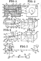
- a scattering cell employing a central body 10 in the form of a rectangular block having a sample cavity 12 containing a sample such as a polymer, colloid or other substance disposed in an appropriate medium.
- the sample cavity is lined with a black plastic liner 14 made of a Teflon plastic although other non-reactive materials can be used instead.
- the outside of liner 14 matches the bore in body 10, both being cylindrical.
- the internal bore of liner 14 is frustroconical and flares in a direction from input side 16 to output side 18 of body 10.
- Input window 20 is held in place by annular cap 22 having external threads matching internal threads in central body 10. Concentric bore 24 in cap 22 is aligned with sample cavity 12.
- a transverse aperture 26 Near the frustroconical base of cavity 12 is a transverse aperture 26, vertically piercing the side of liner 14. Positioned in this fashion, aperture 26 is at the lowest point in cavity 12.
- a conduit 28 is drilled through body 10 to allow aperture 26 to communicate with inlet 30.
- An identical aperture (schematically illustrated hereinafter) is located vertically above aperture 26 in liner 14 at the high point of cavity 12.
- Conduit 31 bored through body 10 allows communication with the high point of liner 14 to outlet 32.
- the upper portion of cavity 12 communicating with outlet 32 is referred to herein as an upper concavity while the lower portion of sample cavity 12 communicating with inlet aperture 26 is referred to herein as a lower concavity.
- prismatic output window 34 shown herein in the shape of a prism having a triangular cross-section. While prism 34 is shown herein as a 45° right triangle, various other angles can be employed instead.
- prism 34 is a conventional prism having highly : polished surfaces. The three functional surfaces of prism 34 are referred to herein as inner face 36, outer face 38, and lateral face 40, the lateral and outer face being orthogonal to each other and disposed at 45° to inner face 36.
- Secured against faces 38 and 40 are rectangular cover plates 33 and 35, respectively, each having rectangular apertures.
- FIG. 3 and 4 an essentially schematic diagram is given of the apparatus of Figs. 1 and 2.
- conduits 28 and 31 are shown emerging vertically upward from the input and output end, respectively, of sample cavity 12.
- the sampling cell is shown partitioned by vertical plane 42 which contains the centerline of the incoming radiation: converging laser light beam 44.
- Beam 44 is illustrated with an exaggerated angle of convergence, focusing at inner face 36 of prism 34.
- Unscattered light and light scattered through a relatively small angle is illustrated as beam 46.
- beam 46 has refracted across inner face 36 so it deflects to the left (that is, to a given side of plane 42) since in this case, the index of refraction of the prism exceeds that of the sample. Similarly, beam 46 is further refracted to the left at outer face 38. It is significant to note that beam 46 intercepts outer face 38 at a non-orthogonal angle. Accordingly, internal reflections do not tend to return to scattering volume 12. Instead such internally reflected light is shown returning along reflection path 48. If this reflected light is not trapped it can be used as it emerges from face 40 as a local oscillator for heterodyning the neighboring scattered light.
- FIG. 5 and 6 an embodiment which is an alternate to that of Figs. 1-4 is illustrated.
- elements bearing the same reference numerals as previously employed are components having ' the same function and similar structure.
- An important difference in the embodiment of Figs. 5 and 6 is the replacement of the previously illustrated input window with prismatic input window 52.
- window 52 is a prism identical to previously described prismatic output window 34.
- This type of input window By using this type of input window, relatively large scattering angles between 90° to 180° that are not easily transmitted through face 40 can be analyzed.
- one such highly scattered beam 54 is shown being transmitted through rear face 56 of prism 52.
- Another less highly scattered beam 58 is shown being transmitted through lateral face 60 of input prismatic window 52. It again will be appreciated that the various angles of convergence and divergence may have been exaggerated to clarify the illustration.
- the scattering system illustrated herein employs source of radiation 62 producing, in this preferred embodiment, monochromatic coherent laser light. While visible radiation is preferred, other frequencies may be employed in different embodiments.
- Output beam 64 from laser 62 is perpendicularly reflected by mirror Ml through pinhole aperture Pl through collimating and focusing lens 66.
- Lens 66 projects beam 64 through pinhole apertures P2 and P3 before illuminating scattering cell 10.
- Light emerging from cell 10 can be detected by a detection means shown herein as first detector 68 and second detector 70.
- detector 70 Another light beam incident on prism 34 and refracted thereby is shown emerging from its lateral face as beam 73 which is reflected to the left by rotatable mirror M3.
- Laser light reflected by mirror M3 is transmitted through pinhole aperture P5 and through analyzer 72 which, in this embodiment, is essentially a polarizing filter.
- Light transmitted through polarizing filter 72 passes through a final pinhole aperture P6 before reaching detector 70.
- the scattering angle of light accepted by detector 70 can be adjusted by rotating mirror M3.
- Each of the detectors 68 and 70 can contain a photomultiplier tube providing data to a system for analyzing the intensity and spectrum of the incoming laser light. In particular, the line-width of the incoming spectrum can be studied.
- detectors 68 and 70 employ a multi-channel autocorrelator for performing the well-known autocorrelation function on discrete time samples to characterise the line-width of incoming light.
- Mirror Ml is spaced 60 millimeters from laser 62 and 125 millimeters from aperture Pl.
- Lens 66 is separated by 90 millimeters from aperture PI and by 265 millimeters from aperture P2.
- Aperture P3 is spaced 55 millimeters from cell 10 and 140 millimeters from aperture P2.
- the spacing between cell 10 and mirrors M3 and M2 is 125 and 70 millimeters, respectively, while the spacing between apertures P5 and P6 is 300 millimeters.
- the spacing between aperture P4 and detector 68 is 420 millimeters. It will be appreciated that the foregoing dimensions can be readily altered depending upon the application.
- Sample cavity 12 can be supplied with a sample from sample source 74 through serially connected apparatus 76.
- Apparatus 76 performs size exclusion chromatography, for example, gel permeation chromatography or high pressure liquid chromatography.
- the output of apparatus 76 is fed through line 30 to sample cavity 12 which is drained by outlet 32.
- Source 74 may provide a sample stream of colloids, polymers, or other substances disposed in an appropriate medium.
- Source 74 feeds chromatographic or filtration apparatus 76. Accordingly, the particles initially arriving in inlet 30 and entering cavity 12 can be larger particles which may or may not be of most interest to the experimenter.
- Collimated laser light beam 64 enters cell 10 and illuminates the sample in cavity 12. Since beam 64 is narrowly focused, the scattering volume illuminated is extremely small and the likelihood of extraneous particles entering the illuminated scattering volume to cause erroneous readings is rather small.
- Unscattered light is refracted through prism 34, emerging as beam 75 which if reflected by mirror M2 does not pass through pinhole aperture P4 and is therefore effectively blocked from detection.
- light scattered at a relatively small angle can emerge from the outer face of prism 34 along beam path 71.
- prism 34 operates to increase the angle separating beams 75 and 71. This phenomena is due to the tendency of the prism to increase divergence among certain rays.
- Beam 71 is ultimately projected into the photomultiplier tube of detector 68 to stimulate its multichannel autocorrelation system.
- strongly scattered light emerges from the lateral face of prism 34 along beam 73.
- Beam 73 is analysed by polarizer 72 which admits only light polarized in one specific orientation into detector 70. The experimenter can obtain the angular distribution of data by adjusting mirrors M2 and M3 to select the desired scattering angle.
- relatively large scattering angles can be detected by detector 70. These large scattering angles are significant when Zimmplots are being obtained for substances having sizes comparable to the wavelength of the incident radiation. Of course, these large scattering angles can be significant where spectral data must be studied at large scattering angles to characterize certain degrees of freedom of the scattering particle evidenced only at these large angles. It is also advantageous to obtain measurements at small and large scattering angles simultaneously. Simultaneous measurements ensures that the data relates to the same type of particles and that the data is validly correlated.
- the data can then be re-analyzed to characterize the new class of particles entering sample chamber 12. It is highly advantageous to be able to obtain large and small scattering angle data in one experiment, sequentially obtaining data for different size particles.
- the refractive index of the sample in cavity 12 can be obtained by observing the extent of refraction caused by prism 34.
- the refractive index of prism 34 is presumably known.
- the size and shape of the prism including the angles between the various faces can be altered depending upon the application.
- the shape of the main body and the liner for the sample cell can be changed depending upon the desired volume, flow rate and flow characteristics.
- a conical cavity is illustrated it will be appreciated that spherical or other shapes may be employed. It is, however, desirable to have a lower and upper concavity for allowing filling and draining, the upper concavity being advantageously used as a bubble trap.
- glass prisms are preferred other optical substances having different optical qualities can be employed instead.
- the dimensions of and materials in various components can be altered depending upon the desired sample volume, speed of analysis, sample temperature etc.
Landscapes
- Physics & Mathematics (AREA)
- Health & Medical Sciences (AREA)
- Life Sciences & Earth Sciences (AREA)
- Chemical & Material Sciences (AREA)
- Analytical Chemistry (AREA)
- Biochemistry (AREA)
- General Health & Medical Sciences (AREA)
- General Physics & Mathematics (AREA)
- Immunology (AREA)
- Pathology (AREA)
- Investigating Or Analysing Materials By Optical Means (AREA)
- Optical Measuring Cells (AREA)
Applications Claiming Priority (2)
| Application Number | Priority Date | Filing Date | Title |
|---|---|---|---|
| US427115 | 1982-09-29 | ||
| US06/427,115 US4565446A (en) | 1982-09-29 | 1982-09-29 | Scattering cells |
Publications (2)
| Publication Number | Publication Date |
|---|---|
| EP0104661A2 true EP0104661A2 (de) | 1984-04-04 |
| EP0104661A3 EP0104661A3 (de) | 1984-12-05 |
Family
ID=23693545
Family Applications (1)
| Application Number | Title | Priority Date | Filing Date |
|---|---|---|---|
| EP83109718A Ceased EP0104661A3 (de) | 1982-09-29 | 1983-09-28 | Lichtstreuungszelle |
Country Status (2)
| Country | Link |
|---|---|
| US (1) | US4565446A (de) |
| EP (1) | EP0104661A3 (de) |
Cited By (9)
| Publication number | Priority date | Publication date | Assignee | Title |
|---|---|---|---|---|
| EP0134627A3 (en) * | 1983-06-10 | 1986-01-15 | Corning Glass Works | Fluid sample chamber for optical analysis |
| EP0181962B1 (de) * | 1984-11-22 | 1989-01-25 | Personal Diagnostics, Inc. | Küvette mit integrierten optischen Elementen |
| EP0186712B1 (de) * | 1984-11-22 | 1989-04-05 | Personal Diagnostics, Inc. | Zusammengesetzte Küvette mit integrierten optischen Elementen und einer elektrischen Schaltung mit in engem Kontakt zu diesen Elementen lichtsendenden und lichtempfindlichen Elementen |
| EP0182618B1 (de) * | 1984-11-15 | 1990-07-11 | Wyatt Technology Corporation | Probenzelle für Lichtstreuungsmessungen |
| US5212393A (en) * | 1990-03-19 | 1993-05-18 | Horiba, Ltd. | Sample cell for diffraction-scattering measurement of particle size distributions |
| US5351118A (en) * | 1990-05-04 | 1994-09-27 | Biometic Aps C/O Dansk Udviklingsfinansiering A/S | Apparatus and method for analyzing particles suspended in a liquid |
| FR2713773A1 (fr) * | 1993-12-09 | 1995-06-16 | Sematech Sarl | Granulomètre laser à effet de prisme. |
| WO2010037817A1 (fr) * | 2008-10-03 | 2010-04-08 | Centre National De La Recherche Scientifique (Cnrs) | Systeme optique anti-reflexion et a large acces pour la mesure d'indicatrices de diffusion de milieux fluides |
| EP2238233A4 (de) * | 2007-12-27 | 2016-01-13 | Bacterioscan Ltd | Nachweisen und zählen von in biologischen flüssigkeiten suspendierten bakterien |
Families Citing this family (16)
| Publication number | Priority date | Publication date | Assignee | Title |
|---|---|---|---|---|
| US4801205A (en) * | 1984-06-30 | 1989-01-31 | Kabushiki Kaisha Toshiba | Particle size measuring apparatus |
| JPS6428578A (en) * | 1987-07-23 | 1989-01-31 | Weston Corp | Radar detector/crime preventor for vehicle |
| US5129723A (en) * | 1991-04-11 | 1992-07-14 | Wyatt Technology Corporation | High performance Zimm chromatography--HPZC |
| US5402237A (en) * | 1992-11-12 | 1995-03-28 | Santa Barbara Research Center | Reflection-free ellipsometry measurement apparatus and method for small sample cells |
| US5701176A (en) * | 1995-07-28 | 1997-12-23 | Precision Detectors, Inc. | High temperature light scattering measurement device comprising a rigid extension tube |
| US6646742B1 (en) * | 2000-02-19 | 2003-11-11 | Mwi, Inc. | Optical device and method for multi-angle laser light scatter |
| GB2442747B (en) * | 2006-10-12 | 2010-05-26 | Optiglass Ltd | Closed cell |
| US7817266B2 (en) | 2007-07-26 | 2010-10-19 | J.A. Woollam Co., Inc. | Small volume cell |
| US8130375B1 (en) * | 2007-07-26 | 2012-03-06 | J.A. Woollam Co., Inc. | Small volume cell |
| JP2010540965A (ja) | 2007-12-05 | 2010-12-24 | オールテック・アソシエイツ・インコーポレーテッド | サンプルの画分を収集しサンプルを分析するための方法および装置 |
| US8493565B1 (en) * | 2008-07-24 | 2013-07-23 | J.A. Wollam Co., Inc. | Small volume cell |
| WO2010068276A1 (en) | 2008-12-10 | 2010-06-17 | Alltech Associates Inc. | Chromatography systems and system components |
| US8314934B2 (en) | 2009-09-01 | 2012-11-20 | Alltech Associates, Inc. | Methods and apparatus for analyzing samples and collecting sample fractions |
| EP4443135A3 (de) * | 2013-08-20 | 2024-12-18 | Yokogawa Fluence Analytics, Inc. | Charakterisierung von polymeren und kolloidlösungen |
| JP6480210B2 (ja) * | 2014-02-28 | 2019-03-06 | アークレイ株式会社 | プラズマ発生用チップ、プラズマ発生装置およびプラズマ分光分析方法 |
| CN113270149B (zh) * | 2021-04-30 | 2022-10-04 | 上海大学 | 基于分子动力学的铁液中钛氧团簇生长及结构的表征方法 |
Family Cites Families (5)
| Publication number | Priority date | Publication date | Assignee | Title |
|---|---|---|---|---|
| DE1192849B (de) * | 1961-02-20 | |||
| US3583817A (en) * | 1970-02-11 | 1971-06-08 | Technicon Instr | Colorimeter including a flow cell having end windows |
| US3843268A (en) * | 1973-07-05 | 1974-10-22 | Beckman Instruments Inc | Sample container for laser light scattering photometers |
| US4053229A (en) * | 1976-01-13 | 1977-10-11 | The United States Of America As Represented By The Administrator Of The National Aeronautics And Space Administration | 2°/90° Laboratory scattering photometer |
| US4265538A (en) * | 1979-10-18 | 1981-05-05 | Leeds & Northrup Company | Optical sample cell for analysis of particles in liquid suspension |
-
1982
- 1982-09-29 US US06/427,115 patent/US4565446A/en not_active Expired - Fee Related
-
1983
- 1983-09-28 EP EP83109718A patent/EP0104661A3/de not_active Ceased
Cited By (10)
| Publication number | Priority date | Publication date | Assignee | Title |
|---|---|---|---|---|
| EP0134627A3 (en) * | 1983-06-10 | 1986-01-15 | Corning Glass Works | Fluid sample chamber for optical analysis |
| EP0182618B1 (de) * | 1984-11-15 | 1990-07-11 | Wyatt Technology Corporation | Probenzelle für Lichtstreuungsmessungen |
| EP0181962B1 (de) * | 1984-11-22 | 1989-01-25 | Personal Diagnostics, Inc. | Küvette mit integrierten optischen Elementen |
| EP0186712B1 (de) * | 1984-11-22 | 1989-04-05 | Personal Diagnostics, Inc. | Zusammengesetzte Küvette mit integrierten optischen Elementen und einer elektrischen Schaltung mit in engem Kontakt zu diesen Elementen lichtsendenden und lichtempfindlichen Elementen |
| US5212393A (en) * | 1990-03-19 | 1993-05-18 | Horiba, Ltd. | Sample cell for diffraction-scattering measurement of particle size distributions |
| US5351118A (en) * | 1990-05-04 | 1994-09-27 | Biometic Aps C/O Dansk Udviklingsfinansiering A/S | Apparatus and method for analyzing particles suspended in a liquid |
| FR2713773A1 (fr) * | 1993-12-09 | 1995-06-16 | Sematech Sarl | Granulomètre laser à effet de prisme. |
| EP2238233A4 (de) * | 2007-12-27 | 2016-01-13 | Bacterioscan Ltd | Nachweisen und zählen von in biologischen flüssigkeiten suspendierten bakterien |
| WO2010037817A1 (fr) * | 2008-10-03 | 2010-04-08 | Centre National De La Recherche Scientifique (Cnrs) | Systeme optique anti-reflexion et a large acces pour la mesure d'indicatrices de diffusion de milieux fluides |
| FR2936871A1 (fr) * | 2008-10-03 | 2010-04-09 | Centre Nat Rech Scient | Systeme optique anti-reflexion et a large acces pour la mesure d'indicatrices de diffusion de milieux fluides. |
Also Published As
| Publication number | Publication date |
|---|---|
| US4565446A (en) | 1986-01-21 |
| EP0104661A3 (de) | 1984-12-05 |
Similar Documents
| Publication | Publication Date | Title |
|---|---|---|
| US4565446A (en) | Scattering cells | |
| EP0182618B1 (de) | Probenzelle für Lichtstreuungsmessungen | |
| US4907884A (en) | Sample cell monitoring system | |
| US4278887A (en) | Fluid sample cell | |
| US3508830A (en) | Apparatus for light scattering measurements | |
| US3975084A (en) | Particle detecting system | |
| US3850525A (en) | Simultaneous multiple measurements in laser photometers | |
| US4088407A (en) | High pressure fluorescence flow-through cuvette | |
| US3819270A (en) | Blood cell analyzer | |
| KR970007077B1 (ko) | 광산란 기술을 이용한 다중-부분식별 분석 방법 | |
| US4265538A (en) | Optical sample cell for analysis of particles in liquid suspension | |
| US5430541A (en) | High efficiency fluorescence flow cell for capillary liquid chromatography or capillary electrophoresis | |
| EP0118896B1 (de) | Teilchenzählapparat | |
| EP2264437B1 (de) | Verbessertes Vorrichtung zum Messen der Streulichtsignale aus einer Flüssigkeitsprobe | |
| EP3376203B1 (de) | Partikelcharakterisierung | |
| EP2361375B1 (de) | Zellaufbau für lichtstreudetektoren mit selbstfokussierenden eigenschaften | |
| EP0899548B1 (de) | Kreuzkorrelationsverfahren und Vorrichtung zur Unterdrückung der Effekte von Mehrfachstreuung | |
| NO300907B1 (no) | Partikkelanalysator | |
| NO301671B1 (no) | Partikkelanalyse for bestemmelse av graden av partiklers symmetri | |
| US3999855A (en) | Illumination system | |
| EP1277038A2 (de) | Verfahren und vorrichtung zur in-situ-spektralanalyse | |
| US4355897A (en) | Near-simultaneous measurements at forward and back scatter angles in light scattering photometers | |
| US5572321A (en) | Detector for measuring the luminous intensity scattered by thin films of colloidal media | |
| AU2009300424A1 (en) | An arrangement adapted for spectral analysis of high concentrations of gas | |
| EP1808687A2 (de) | Absolutmessungszentrifuge |
Legal Events
| Date | Code | Title | Description |
|---|---|---|---|
| PUAI | Public reference made under article 153(3) epc to a published international application that has entered the european phase |
Free format text: ORIGINAL CODE: 0009012 |
|
| AK | Designated contracting states |
Designated state(s): AT BE CH DE FR GB IT LI LU NL SE |
|
| PUAL | Search report despatched |
Free format text: ORIGINAL CODE: 0009013 |
|
| AK | Designated contracting states |
Designated state(s): AT BE CH DE FR GB IT LI LU NL SE |
|
| 17P | Request for examination filed |
Effective date: 19850603 |
|
| 17Q | First examination report despatched |
Effective date: 19860923 |
|
| R17C | First examination report despatched (corrected) |
Effective date: 19870506 |
|
| STAA | Information on the status of an ep patent application or granted ep patent |
Free format text: STATUS: THE APPLICATION HAS BEEN REFUSED |
|
| 18R | Application refused |
Effective date: 19880801 |
|
| RIN1 | Information on inventor provided before grant (corrected) |
Inventor name: CHU, BENJAMIN |