EP0104687A1 - Mittel zur Inbetriebnahme von Natriumentladungslampen hoher Intensität, um Lampenspannungsänderungen während der Lebensdauer der Lampe zu reduzieren - Google Patents
Mittel zur Inbetriebnahme von Natriumentladungslampen hoher Intensität, um Lampenspannungsänderungen während der Lebensdauer der Lampe zu reduzieren Download PDFInfo
- Publication number
- EP0104687A1 EP0104687A1 EP83201246A EP83201246A EP0104687A1 EP 0104687 A1 EP0104687 A1 EP 0104687A1 EP 83201246 A EP83201246 A EP 83201246A EP 83201246 A EP83201246 A EP 83201246A EP 0104687 A1 EP0104687 A1 EP 0104687A1
- Authority
- EP
- European Patent Office
- Prior art keywords
- lamp
- operating
- wattage
- voltage
- trapezoidal
- Prior art date
- Legal status (The legal status is an assumption and is not a legal conclusion. Google has not performed a legal analysis and makes no representation as to the accuracy of the status listed.)
- Granted
Links
- 229910052708 sodium Inorganic materials 0.000 title claims abstract description 12
- 239000011734 sodium Substances 0.000 title claims abstract description 12
- DGAQECJNVWCQMB-PUAWFVPOSA-M Ilexoside XXIX Chemical compound C[C@@H]1CC[C@@]2(CC[C@@]3(C(=CC[C@H]4[C@]3(CC[C@@H]5[C@@]4(CC[C@@H](C5(C)C)OS(=O)(=O)[O-])C)C)[C@@H]2[C@]1(C)O)C)C(=O)O[C@H]6[C@@H]([C@H]([C@@H]([C@H](O6)CO)O)O)O.[Na+] DGAQECJNVWCQMB-PUAWFVPOSA-M 0.000 title description 9
- 230000001965 increasing effect Effects 0.000 claims abstract description 23
- 230000000630 rising effect Effects 0.000 claims abstract description 5
- 230000003466 anti-cipated effect Effects 0.000 claims abstract description 4
- 239000003990 capacitor Substances 0.000 description 9
- 238000004804 winding Methods 0.000 description 6
- 238000013459 approach Methods 0.000 description 2
- 238000010276 construction Methods 0.000 description 2
- 238000010586 diagram Methods 0.000 description 2
- 230000000694 effects Effects 0.000 description 2
- 230000001939 inductive effect Effects 0.000 description 2
- XUIMIQQOPSSXEZ-UHFFFAOYSA-N Silicon Chemical compound [Si] XUIMIQQOPSSXEZ-UHFFFAOYSA-N 0.000 description 1
- 230000003247 decreasing effect Effects 0.000 description 1
- 238000013461 design Methods 0.000 description 1
- 238000011161 development Methods 0.000 description 1
- 238000000034 method Methods 0.000 description 1
- 238000009877 rendering Methods 0.000 description 1
- 239000004065 semiconductor Substances 0.000 description 1
- 229910052710 silicon Inorganic materials 0.000 description 1
- 239000010703 silicon Substances 0.000 description 1
- 239000007858 starting material Substances 0.000 description 1
- 238000012360 testing method Methods 0.000 description 1
- 235000012431 wafers Nutrition 0.000 description 1
Images



Classifications
-
- H—ELECTRICITY
- H05—ELECTRIC TECHNIQUES NOT OTHERWISE PROVIDED FOR
- H05B—ELECTRIC HEATING; ELECTRIC LIGHT SOURCES NOT OTHERWISE PROVIDED FOR; CIRCUIT ARRANGEMENTS FOR ELECTRIC LIGHT SOURCES, IN GENERAL
- H05B41/00—Circuit arrangements or apparatus for igniting or operating discharge lamps
- H05B41/14—Circuit arrangements
- H05B41/36—Controlling
- H05B41/38—Controlling the intensity of light
- H05B41/39—Controlling the intensity of light continuously
- H05B41/392—Controlling the intensity of light continuously using semiconductor devices, e.g. thyristor
Definitions
- This invention relates to HID sodium lamps and, more particularly, to a device provided with means for operating such lamps in order to minimize lamp voltage variations throughout lamp life.
- HID high-intensity-discharge
- HID sodium lamps are designed to operate with an increased loading in order to improve the color rendering of objects illuminated thereby, such as described in U.S. Patent No.4,230,964 dated October 28, 1980 to Bhalla.
- This type of HID sodium lamp tends to display shifts in the operating lamp color temperature with increasing lamp voltage. While the overall performance of the lamp is not affected by such shifts in lamp color temperature, when a series of such lamps are operated in side-by-side fixtures, difference in the color appearance of such proximate lamps can be considered objectionable from an esthetic standpoint.
- a device provided with means for operating a high-pressure-sodium high-intensity-discharge lamp in such manner as to substantially decrease variations in lamp operating voltage throughout lamp life.
- All such sodium HID lamps have a nominal rated operating wattage and a nominal rated operating voltage.
- the lamps characteristically display an increasing operating voltage throughout lamp life resulting in established standards which specify that the permissible relative wattage and voltage characteristics which are experienced throughout expected lamp operating life fall within the confines of an established trapezoidal figure on a graph wherein increasing lamp wattage is linearly plotted on the axis of ordinates and increasing lamp voltage is linearly plotted on the axis of abscissas.
- the parallel sides of the trapezoidal figure are defined by minimum permissible and maximum permissible operating lamp wattages and the remaining sides of the trapezoidal figure are defined by two lines of sharply rising positive slope wherein small increases in lamp operating voltage are reflected as relatively large increases in lamp operating wattage and which represent desired minimum permissible lamp voltages and desired maximum permissible lamp voltages at lamp operating wattages which may vary from the minimum permissible to the maximum permissible values as specified.
- the operating characteristics of the lamp throughout its normally anticipated life will vary somewhat with variations in line voltage but are describable by a humped curve which enters into the trapezoidal figure through the line representing minimum permissible lamp voltages and which curve exits from the trapezoidal figure through the line representing maximum permissible lamp voltages.
- each basically different lamp type has established therefor its own trapezoidal figure by which its performance is measured.
- the device is provided with means which operate the lamp for an initially relatively short period of time until the lamp voltage has attained a predetermined value and the operating wattage consumption of the lamp is relatively high as compared to the specified minimum wattage value at which the lamp can be operated. Thereafter, and commencing with the relatively high wattage consumption at which the lamp operates at the termination of the first period of time, the means continue to operate the lamp but in such modified manner that the operating characteristic curve of lamp wattage consumption versus increasing lamp operating voltage displays a slope which is negative in nature and which does not exceed a lamp operating wattage drop of about 1.5 percent per one volt increase in lamp operating voltage, in order to insure stable lamp operation. The means continue to operate the lamp in such manner that the operating characteristic curve ultimately exits from the trapezoidal figure proximate the intersection of the line which describes the minimum permissible wattage value and the line which describes the maximum permissible voltage values.
- ANSI trapezoids Such a trapezoid is shown in Figure 1 for a lamp which is nominally rated at 400 watts, 100 volts, with the nominal lamp rating being indicated by (+). Because of the increasing lamp voltage which is exhibited throughout lamp life, the industry specifies that the relative wattage and voltage operating characteristics which are experienced throughout expected lamp life should fall within the confines of these trapezoids.
- the parallel sides of the trapezoidal figure are defined by horizontal lines which set the desired minimum permissible AA and maximum permissible operating lamp wattages BB.
- the remaining sides of the trapzoidal figure are defined by two lines of sharply rising positive slope wherein small increases in lamp operating voltage are reflected as relatively large increases in operating lamp wattage and which represent desired minimum permissible lamp voltages CC and desired maximum permissible lamp voltages DD at operating wattages which vary from the desired minimum permissible AA to the maximum permissible wattages BB.
- the operating characteristics of such a lamp throughout its normally anticipated life are describable by a generally humped curve which enters into the trapezoidal figure through the line representing minimum permissible lamp voltages CC and which curve exits from the trapezoidal figure through the line which represents maximum permissible lamp voltages DD.
- Another factor which enters into lamp performance is line voltage and for a typical ballasted lamp of this rating, 10 percent high line voltage will produce a lamp performance curve such as is set forth in the curve designated A1.
- a lamp-ballast which is operated at nominal line voltages has a typical lamp performance such as shown in curve A2, and a lamp-ballast combination operated at 10 percent low line voltage has a typical lamp operating curve such as shown in curve A3.
- the operating lamp voltage will have increased sufficiently that once the lamp is warmed up, the ballast will not sustain its operation and it tends to cycle "on and off" until the lamp is replaced.
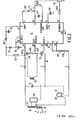
- An HID sodium lamp can be operated in accordance with the present invention from any of a variety of different circuit and ballast arrangements, but in its preferred form, a so-called lead ballast circuit is modified to incorporate a controlling module P such as shown in Figure 2.
- the basic lead-type ballast apparatus 20 has apparatus input terminals A and B adapted to be connected across a source of AC energizing potential and apparatus output terminals E and D across which the lamp 22 to be operated is adapted to be connected.
- the ballast apparatus comprises an inductive reactance portion designated X L and a capacitive reactance portion designated X C .
- the inductive reactance portion comprises a conventional current-limiting high- reactance transformer means which has a primary winding 30 connected to the apparatus input terminals A and B and a secondary winding 32 terminating in secondary winding output terminals C and D.
- the capacitive reactance portion comprises the capacitor X c connected in circuit between the secondary winding means output terminal C and the apparatus output terminal E.
- the high reactance transformer X L can have an outotransformer construction or it can be formed with separate windings.
- the basic modifying device comprises additional inductance means 52 connected in series with a gate-controlled AC semiconductor switching means 56 which has a high impedance open position and a low impedance closed position and gate terminal means 66 which connect to the basic sensing and programming means P as described hereinafter.
- the switching means 56 When the switching means 56 is open, the modified ballast apparatus delivers a first level of current to an operating lamp and when the switching means is closed, the modifying ballast apparatus delivers a second and lower level of current to an operating lamp.
- the sensing and programming means P is operable to sense the lamp operating voltage and to generate an output control signal which is indicative of the operating wattage desired for the operating lamp.
- the programming means has its output connected to the gate terminal 66 of the switch 56 to control the relative proportion of time the switching means is open and closed in order to control in programmed fashion the operating wattage desired for the operating lamp.
- connections to the conventional lead-type ballast are made at the indicated points C, D and E.
- a conventional starter 105 which cooperates with the secondary winding 32 in order to provide high voltage starting pulses, such as 2500 volts.
- high voltage starting pulses such as 2500 volts.
- the device with circuit as shown in Figure 3 periodically measures the lamp operating voltage, once stable lamp operating conditions are achieved, in order to generate output signals which are representative of the measured voltages developed across the operating lamp. These are used to actuate means which cause the gate drive for the switch 56 to be actuated at a predetermined earlier time in each half cycle of the AC energizing potential at the measured lamp voltages increase. In other words, as the lamp operating voltage increase, the lamp wattage consumption is decreased at a predetermined rate in order that the lamp voltage increase is minimized.
- the modified control senses lamp voltage and reduces the lamp power once the voltage has passed a predetermined value of about 110 VAC in the case of a lamp rated at 100 VAC. Once the control is in effect, a representation wattage decrease, when plotted on a curve of watts versus volts, will display a negative slope of about one percent decrease in wattage per one volt increase in lamp operating voltage.
- the resistor R26 parallels the integrating capacitor C11 and the voltage which appears across C11 is "zero" until the lamp is warmed up and its operating voltage achieves a value of approximately 110 VAC. At this time, the lamp voltage signal begins to exceed the reference signal causing the voltage across C11 to increase. This in turn causes the AC switch 56 to turn “on” which in turn reduces lamp power, thereby reducing the tendency for lamp voltage increase.
- the current through R26 is proportional to the voltage across C11 and is of the same polarity as the internal reference current, described hereinafter, which flows toward the INTEGRATING CAP terminal 14'. The current through R26 therefore has the effect of increasing this reference value.
- Potentiometer P2 is used to adjust the bias current into BIAS TERMINAL 4 1 .
- the ramp capacitor charging current equals twice the bias current and thus the ramp height can be adjusted.
- the maximum height is set equal to +E which provides a generally uniform slope for the lamp power versus voltage curve.
- the second potentiometer P2 sets the lamp voltage value at which the control becomes active. At the present time, for a lamp having a nominal voltage of 100 volts, the control is set to become operative when the measured lamp operating voltage reaches a value of about 110 AC.
- the integrated circuit U1 design is based upon a "master array” concept which yields silicon wafers with thousands of identical "chips” which are completely processed except for the final device interconnect pattern on the surface of the chip.
- the advantage of this process is reduced cost and development time.
- the chip circuitry is shown in detail in Figure 4 and in the following Table II are descriptions of the IC pins along with their functioning.
- Table III is a general description of the components of the I.C. chip.
- the lamp operates without any control until its wattage consumption, as determined by its measured voltage, is relatively high as compared to the specified minimum wattage value at which the lamp can be operated.
- the initial operating lamp wattage, prior to control thereof will approximate its nominal value, such as 250 watts. However, this need not be the case and the initial lamp wattage, prior to control, can be higher or lower if desired.
- the control means becomes effective and thereafter and commencing with the relatively high initial lamp wattage consumption the means operate the lamp in such manner that the operating characteristics curve of lamp wattage consumption versus increasing lamp voltage displays a slope which is negative in nature.
- This slope should not exceed a lamp operating wattage drop of about 1.5 percent per one volt increase in lamp operating volts in order to insure stable lamp operation. In other words, if the lamp wattage consumption is dropped too rapidly, some lamp instability may result.
- the means then continue to operate the lamp in this manner until the operating characteristic curve ultimately exits from the trapezoidal figure proximate the intersection of the line which describes the minimum permissible wattage value and the line which describes the maximum permissible voltage values.
- the resulting mode of operation is shown in Figure 5 for a lamp which has a nominal rating of 250 waats, 100 volts.
- the curve A4 is plotted for a lamp operated from a line voltage which is 10 percent higher than nominal, the curve A5 is for nominal line voltage operation and the curve A6 is for 10 percent under nominal line voltage.
- a similar set of curves is shown in Figure 6 for a 150 watt lamp wherein the lamp trapezoid is plotted with the lamp operating characteristics shown thereon.
- the curve A7 is for 10 percent over-line voltage, the curve A8 is taken for nominal line voltage and the curve A9 is taken for 10 percent under-line voltage.
- FIG. 7 A similar set of curves is shown in Figure 7 for a lamp nominally rated at 400 watts, 100 volts wherein the curve A10 is taken for a lamp operated from 10 percent over-line volts, the curve A11 is taken for a lamp operated from nominal line voltage and the curve A12 is taken for a lamp operated from 10 percent under-line voltage.
- a commercial embodiment for such a lamp-ballast combination would desirably utilize a slightly larger value of capacitive reactance, (X c ), such as 52 tfFD instead of 48 MFD, to raise the curves somewhat.
- the lamp control means are not operative until the lamp is warmed up and the add-on inductor 52 can be wound to operate at the maximum capacitor voltage (X C ) expected with minimum lamp voltages, typically in the order of about 80 volts.
- X C maximum capacitor voltage
- the size of the series capacitor X c increases with increasing ballast rating. At a given lamp voltage, the higher current encountered with increasing ballast rating thus produces approximately the same voltage drop, across the.series ballast capacitor X C .
- evry lead-type ballast rating will have the same maximum voltage rating for the add-on industor 52.
- the actual value of the inductor 52 is not critical and a typical rating for the inductor is 159 mH.
- the device means do operate the lamps, after the relatively short first period of time, in such manner that the curve of power versus voltage has a negative slope which is generally uniform, a shown in Figures 5-7.
- the value of the add-on inductor 52 could be increased so that with the add-on inductor 52 phased "in” at all times, the characteristic curve of power versus volts would approach, but not fall beneath, the minimum permissible lamp wattage line of the appropriate trapezoid.
- the lamp 22 would be operated during the relatively short first period of time in the manner as described hereinbefore.
- the negative slope of the lamp operating curve would be increased so as to approach the value of about 1.5% decrease in wattage per one volt increase in lamp voltage.
- This mode of lamp operation would be continued until the add-on inductor 52 was fully phased "in".
- the operating characteristic curve would then assume a generally horizontal slope for the remainder of the lamp life until it exited from the trapezoid, proximate the lower right-hand corner thereof.
- the add-on inductor 52 could be increased from 159 mH to 700 mH.
Landscapes
- Circuit Arrangements For Discharge Lamps (AREA)
Applications Claiming Priority (2)
| Application Number | Priority Date | Filing Date | Title |
|---|---|---|---|
| US06/414,276 US4475065A (en) | 1982-09-02 | 1982-09-02 | Method of operating HID sodium lamp to minimize lamp voltage variation throughout lamp life |
| US414276 | 1982-09-02 |
Publications (2)
| Publication Number | Publication Date |
|---|---|
| EP0104687A1 true EP0104687A1 (de) | 1984-04-04 |
| EP0104687B1 EP0104687B1 (de) | 1987-03-25 |
Family
ID=23640753
Family Applications (1)
| Application Number | Title | Priority Date | Filing Date |
|---|---|---|---|
| EP83201246A Expired EP0104687B1 (de) | 1982-09-02 | 1983-08-31 | Mittel zur Inbetriebnahme von Natriumentladungslampen hoher Intensität, um Lampenspannungsänderungen während der Lebensdauer der Lampe zu reduzieren |
Country Status (5)
| Country | Link |
|---|---|
| US (1) | US4475065A (de) |
| EP (1) | EP0104687B1 (de) |
| JP (1) | JPS59139597A (de) |
| CA (1) | CA1233505A (de) |
| DE (1) | DE3370574D1 (de) |
Cited By (4)
| Publication number | Priority date | Publication date | Assignee | Title |
|---|---|---|---|---|
| EP0164774A1 (de) * | 1984-05-14 | 1985-12-18 | Philips Patentverwaltung GmbH | Schaltungsanordnung zur Regelung der Brennspannung von Hochdruckgasentladungslampen |
| EP0240080A1 (de) * | 1986-04-04 | 1987-10-07 | Koninklijke Philips Electronics N.V. | Schaltungsanordnung zum Betrieb einer Hochdrucknatriumentladungslampe |
| EP0445882A3 (en) * | 1990-03-08 | 1991-10-30 | N.V. Philips' Gloeilampenfabrieken | Switching arrangement |
| DE4436825A1 (de) * | 1994-06-28 | 1996-01-04 | Matsushita Electric Works Ltd | Vorrichtung zum Betreiben einer Hochdruck-Gasentladungslampe |
Families Citing this family (17)
| Publication number | Priority date | Publication date | Assignee | Title |
|---|---|---|---|---|
| US4645982A (en) * | 1982-11-15 | 1987-02-24 | Canon Kabushiki Kaisha | Load control unit in an image forming apparatus |
| US5610480A (en) * | 1983-08-13 | 1997-03-11 | Canon Kabushiki Kaisha | Control apparatus for copying machine or the like |
| US4999547A (en) | 1986-09-25 | 1991-03-12 | Innovative Controls, Incorporated | Ballast for high pressure sodium lamps having constant line and lamp wattage |
| US5428268A (en) * | 1993-07-12 | 1995-06-27 | Led Corporation N.V. | Low frequency square wave electronic ballast for gas discharge |
| US6681110B1 (en) * | 1999-07-02 | 2004-01-20 | Musco Corporation | Means and apparatus for control of remote electrical devices |
| JP3852299B2 (ja) | 2001-05-11 | 2006-11-29 | ウシオ電機株式会社 | 光源装置 |
| US7956556B1 (en) | 2004-02-24 | 2011-06-07 | Musco Corporation | Apparatus and method for compensating for reduced light output of a solid-state light source having a lumen depreciation characteristic over its operational life |
| US7956551B1 (en) | 2004-02-24 | 2011-06-07 | Musco Corporation | Apparatus and method for discretionary adjustment of lumen output of light sources having lamp lumen depreciation characteristic compensation |
| US8770796B2 (en) | 2004-02-24 | 2014-07-08 | Musco Corporation | Energy efficient high intensity lighting fixture and method and system for efficient, effective, and energy saving high intensity lighting |
| US7176635B2 (en) * | 2004-02-24 | 2007-02-13 | Musco Corporation | Apparatus and method for compensating for reduced light output of a light source having a lumen depreciation characteristic over its operational life |
| US7843144B2 (en) * | 2004-02-24 | 2010-11-30 | Musco Corporation | Method and apparatus for retrofitting HID lamps with system to periodically adjust operating wattage |
| US20090051299A1 (en) * | 2005-01-18 | 2009-02-26 | Musco Corporation | Linear reactor ballast for sports lighting fixtures |
| JP4941855B2 (ja) * | 2005-04-22 | 2012-05-30 | 西芝電機株式会社 | 電動送風機 |
| US8288965B1 (en) | 2007-02-23 | 2012-10-16 | Musco Corporation | Apparatus and method for switching in added capacitance into high-intensity discharge lamp circuit at preset times |
| US8247990B1 (en) | 2008-12-05 | 2012-08-21 | Musco Corporation | Apparatus, method, and system for improved switching methods for power adjustments in light sources |
| CN103392094B (zh) | 2011-02-25 | 2016-12-21 | 玛斯柯有限公司 | 紧凑可调的led照明装置以及长期运行的方法和系统 |
| JP6939523B2 (ja) * | 2017-12-25 | 2021-09-22 | セイコーエプソン株式会社 | 放電灯駆動装置、光源装置、プロジェクター、および放電灯駆動方法 |
Citations (3)
| Publication number | Priority date | Publication date | Assignee | Title |
|---|---|---|---|---|
| US3925705A (en) * | 1974-05-15 | 1975-12-09 | Westinghouse Electric Corp | Low-cost power-reducing device for hid lamp |
| US3987339A (en) * | 1975-12-10 | 1976-10-19 | Frequency Technology, Inc. | Constant power lamp ballast |
| US4162429A (en) * | 1977-03-11 | 1979-07-24 | Westinghouse Electric Corp. | Ballast circuit for accurately regulating HID lamp wattage |
Family Cites Families (3)
| Publication number | Priority date | Publication date | Assignee | Title |
|---|---|---|---|---|
| US2470460A (en) * | 1948-06-05 | 1949-05-17 | Hanovia Chemical & Mfg Co | Wattage controlling system |
| US3778669A (en) * | 1972-03-13 | 1973-12-11 | North American Rockwell | Magnetic deflection system for depressed-center sector scan display |
| US3989976A (en) * | 1975-10-07 | 1976-11-02 | Westinghouse Electric Corporation | Solid-state hid lamp dimmer |
-
1982
- 1982-09-02 US US06/414,276 patent/US4475065A/en not_active Expired - Fee Related
-
1983
- 1983-08-30 JP JP58158928A patent/JPS59139597A/ja active Pending
- 1983-08-31 DE DE8383201246T patent/DE3370574D1/de not_active Expired
- 1983-08-31 EP EP83201246A patent/EP0104687B1/de not_active Expired
- 1983-09-01 CA CA000435903A patent/CA1233505A/en not_active Expired
Patent Citations (3)
| Publication number | Priority date | Publication date | Assignee | Title |
|---|---|---|---|---|
| US3925705A (en) * | 1974-05-15 | 1975-12-09 | Westinghouse Electric Corp | Low-cost power-reducing device for hid lamp |
| US3987339A (en) * | 1975-12-10 | 1976-10-19 | Frequency Technology, Inc. | Constant power lamp ballast |
| US4162429A (en) * | 1977-03-11 | 1979-07-24 | Westinghouse Electric Corp. | Ballast circuit for accurately regulating HID lamp wattage |
Cited By (6)
| Publication number | Priority date | Publication date | Assignee | Title |
|---|---|---|---|---|
| EP0164774A1 (de) * | 1984-05-14 | 1985-12-18 | Philips Patentverwaltung GmbH | Schaltungsanordnung zur Regelung der Brennspannung von Hochdruckgasentladungslampen |
| US4891563A (en) * | 1984-05-14 | 1990-01-02 | U.S. Philips Corporation | Circuit arrangement for adjusting the operating voltage of high-pressure gas discharge lamps |
| EP0240080A1 (de) * | 1986-04-04 | 1987-10-07 | Koninklijke Philips Electronics N.V. | Schaltungsanordnung zum Betrieb einer Hochdrucknatriumentladungslampe |
| EP0445882A3 (en) * | 1990-03-08 | 1991-10-30 | N.V. Philips' Gloeilampenfabrieken | Switching arrangement |
| DE4436825A1 (de) * | 1994-06-28 | 1996-01-04 | Matsushita Electric Works Ltd | Vorrichtung zum Betreiben einer Hochdruck-Gasentladungslampe |
| DE4436825C2 (de) * | 1994-06-28 | 2001-02-22 | Matsushita Electric Works Ltd | Verfahren und elektronische Vorschalteinrichtung zum Betreiben einer Hochdruck-Gasentladungslampe |
Also Published As
| Publication number | Publication date |
|---|---|
| EP0104687B1 (de) | 1987-03-25 |
| CA1233505A (en) | 1988-03-01 |
| US4475065A (en) | 1984-10-02 |
| DE3370574D1 (en) | 1987-04-30 |
| JPS59139597A (ja) | 1984-08-10 |
Similar Documents
| Publication | Publication Date | Title |
|---|---|---|
| EP0104687B1 (de) | Mittel zur Inbetriebnahme von Natriumentladungslampen hoher Intensität, um Lampenspannungsänderungen während der Lebensdauer der Lampe zu reduzieren | |
| EP0311424B1 (de) | Hochfrequenzvorschaltgerät für Entladungsgaslampen | |
| EP0098285B2 (de) | Elektronischer hochfrequenzgesteuerter apparat zum betrieb von gasentladungslampen | |
| US4501994A (en) | Ballast modifying device and lead-type ballast for programming and controlling the operating performance of an hid sodium lamp | |
| US5220250A (en) | Fluorescent lamp lighting arrangement for "smart" buildings | |
| US4712045A (en) | Electric arrangement for regulating the luminous intensity of at least one discharge lamp | |
| EP0836793B1 (de) | Stromversorgung zum betreiben und zünden einer entladungslampe | |
| EP0413991A1 (de) | Entladungslampenversorgungsapparat zur Steuerung der Lampe, abhängig von ihrem Typ | |
| US4684851A (en) | DC/AC converter for feeding a metal vapor discharge tube | |
| KR20030045835A (ko) | 역률 보정 기능을 갖는 안정기 제어 집적 회로 | |
| US5933340A (en) | Frequency controller with loosely coupled transformer having a shunt with a gap and method therefor | |
| US4503364A (en) | Programming and control device for modified lead ballast for HID lamps | |
| CA1144592A (en) | Discharge device ballast component which provides both voltage transformation and variable inductive reactance | |
| US5051667A (en) | Arc interrupting lamp ballast | |
| JPH04259798A (ja) | けい光ランプ照明装置 | |
| US4243926A (en) | Load responsive voltage controlled motor | |
| CA2288087C (en) | Ferroresonant transformer ballast for maintaining the current of gas discharge lamps at a predetermined value | |
| EP0239420B1 (de) | Hochfrequenz-Vorschaltgerät für Gasentladungslampen | |
| US4458181A (en) | Lead-type ballast apparatus with improved power factor for operating a high-intensity-discharge sodium lamp | |
| US4455595A (en) | Packaged add-on device for lead-type ballast and luminaire which incorporates such packaged add-on device | |
| JP3369468B2 (ja) | インバータ回路 | |
| EP1423992B1 (de) | Schaltungsanordnung | |
| JPH0143840Y2 (de) | ||
| JPH09247957A (ja) | 自励式圧電トランスインバータ | |
| JPH0334295A (ja) | 放電灯点灯装置 |
Legal Events
| Date | Code | Title | Description |
|---|---|---|---|
| PUAI | Public reference made under article 153(3) epc to a published international application that has entered the european phase |
Free format text: ORIGINAL CODE: 0009012 |
|
| AK | Designated contracting states |
Designated state(s): DE FR GB |
|
| 17P | Request for examination filed |
Effective date: 19840601 |
|
| RAP1 | Party data changed (applicant data changed or rights of an application transferred) |
Owner name: NORTH AMERICAN PHILIPS LIGHTING CORPORATION |
|
| 17Q | First examination report despatched |
Effective date: 19860509 |
|
| GRAA | (expected) grant |
Free format text: ORIGINAL CODE: 0009210 |
|
| AK | Designated contracting states |
Kind code of ref document: B1 Designated state(s): DE FR GB |
|
| REF | Corresponds to: |
Ref document number: 3370574 Country of ref document: DE Date of ref document: 19870430 |
|
| ET | Fr: translation filed | ||
| PLBE | No opposition filed within time limit |
Free format text: ORIGINAL CODE: 0009261 |
|
| STAA | Information on the status of an ep patent application or granted ep patent |
Free format text: STATUS: NO OPPOSITION FILED WITHIN TIME LIMIT |
|
| 26N | No opposition filed | ||
| REG | Reference to a national code |
Ref country code: GB Ref legal event code: 732 |
|
| PGFP | Annual fee paid to national office [announced via postgrant information from national office to epo] |
Ref country code: GB Payment date: 19910731 Year of fee payment: 9 |
|
| REG | Reference to a national code |
Ref country code: FR Ref legal event code: TP |
|
| PGFP | Annual fee paid to national office [announced via postgrant information from national office to epo] |
Ref country code: FR Payment date: 19910821 Year of fee payment: 9 |
|
| PGFP | Annual fee paid to national office [announced via postgrant information from national office to epo] |
Ref country code: DE Payment date: 19911028 Year of fee payment: 9 |
|
| PG25 | Lapsed in a contracting state [announced via postgrant information from national office to epo] |
Ref country code: GB Effective date: 19920831 |
|
| GBPC | Gb: european patent ceased through non-payment of renewal fee |
Effective date: 19920831 |
|
| PG25 | Lapsed in a contracting state [announced via postgrant information from national office to epo] |
Ref country code: FR Effective date: 19930430 |
|
| PG25 | Lapsed in a contracting state [announced via postgrant information from national office to epo] |
Ref country code: DE Effective date: 19930501 |
|
| REG | Reference to a national code |
Ref country code: FR Ref legal event code: ST |