EP0104854A2 - Procédé de magnétisation de la paroi d'un puits - Google Patents
Procédé de magnétisation de la paroi d'un puits Download PDFInfo
- Publication number
- EP0104854A2 EP0104854A2 EP83305478A EP83305478A EP0104854A2 EP 0104854 A2 EP0104854 A2 EP 0104854A2 EP 83305478 A EP83305478 A EP 83305478A EP 83305478 A EP83305478 A EP 83305478A EP 0104854 A2 EP0104854 A2 EP 0104854A2
- Authority
- EP
- European Patent Office
- Prior art keywords
- well
- casing
- magnetizing
- drilling
- magnetic
- Prior art date
- Legal status (The legal status is an assumption and is not a legal conclusion. Google has not performed a legal analysis and makes no representation as to the accuracy of the status listed.)
- Withdrawn
Links
Images


Classifications
-
- E—FIXED CONSTRUCTIONS
- E21—EARTH OR ROCK DRILLING; MINING
- E21B—EARTH OR ROCK DRILLING; OBTAINING OIL, GAS, WATER, SOLUBLE OR MELTABLE MATERIALS OR A SLURRY OF MINERALS FROM WELLS
- E21B7/00—Special methods or apparatus for drilling
- E21B7/04—Directional drilling
-
- E—FIXED CONSTRUCTIONS
- E21—EARTH OR ROCK DRILLING; MINING
- E21B—EARTH OR ROCK DRILLING; OBTAINING OIL, GAS, WATER, SOLUBLE OR MELTABLE MATERIALS OR A SLURRY OF MINERALS FROM WELLS
- E21B47/00—Survey of boreholes or wells
- E21B47/02—Determining slope or direction
- E21B47/022—Determining slope or direction of the borehole, e.g. using geomagnetism
- E21B47/0228—Determining slope or direction of the borehole, e.g. using geomagnetism using electromagnetic energy or detectors therefor
-
- G—PHYSICS
- G01—MEASURING; TESTING
- G01V—GEOPHYSICS; GRAVITATIONAL MEASUREMENTS; DETECTING MASSES OR OBJECTS; TAGS
- G01V3/00—Electric or magnetic prospecting or detecting; Measuring magnetic field characteristics of the earth, e.g. declination, deviation
- G01V3/18—Electric or magnetic prospecting or detecting; Measuring magnetic field characteristics of the earth, e.g. declination, deviation specially adapted for well-logging
- G01V3/26—Electric or magnetic prospecting or detecting; Measuring magnetic field characteristics of the earth, e.g. declination, deviation specially adapted for well-logging operating with magnetic or electric fields produced or modified either by the surrounding earth formation or by the detecting device
Definitions
- the borehole of producing oil and gas wells is typically lined from top to bottom with steel casing anchored by a sheath of cement that is securely and circumferentially bonded to both the casing and the wall of the wellbore.
- Offshore wells are sometimes abandoned with no equipment projecting above the water surface. Oftentimes wells are drilled at extreme depths with the drilled wellbore deviating substantially. from the vertical. There is, therefore, the need for a reliable method of locating the wellhead of such abandoned offshore wells or for locating the bottom of a deviated well, especially in the case of a well blowout when a relief well is to be drilled to intersect the deviated well at a point above or near the blowout.
- the direction and position of the production wellbore was determined at the time of drilling by running hole direction surveys and processing the directional data for wellbore position.
- the directional measurements are commonly made using a magnetic compass and inclinometer. The standard deviation of these directional measurements is not accurately known, but is probably greater than the resolution of the instruments.
- bias errors The largest bias error is probably in the compass reading caused mostly by poor calibration and the drill pipe magnetic disturbance.
- the total directional bias error can range up to a few degrees or even more.
- Another method that has been used in such well location efforts is by searching with a magnetometer in the well being drilled for the magnetic anomaly created by the well casing of the producing well.
- the natural magnetization of the well casing due to the earth's magnetic field produces an anomaly in the total magnetic field which may be detected with a proton magnetometer at distances up to a few hundred feet.
- a method for magnetizing well casing by means of an internal magnetizer being advanced through the well casing to create a magnetic anomaly along such well casing The direction of the magnetic field of the magnetizer travels through the well casing so as to create a plurality of magnetic flux leakage points along the well casing.
- the distance between the magnetic flux leakage points is such that a desired magnetic field strength is created along the well casing at a desired radial distance outward from the well casing. More particularly, the desired magnetic field strength is created at a radial distance outward from the well casing at least equal to the distance between the magnetic flux leakage points.
- the present invention further provides a method of drilling intersecting wells.
- a first well is directionally drilled toward an intersect position along a second well having its casing magnetized at least along that portion of the second well to be intersected by the first well.
- the anomaly of the magnetized casing of the second well at the intersect position is sensed from a position within the first well as the directional drilling of the first well approaches the second well.
- the drilling of the first well is directed toward the intersect position on the second well in response to the sensed anomaly.
- the sensing of the anomaly of the second well includes the detection of magnetic flux leakage at a plurality of spaced apart locations along the casing of the second well, such magnetic flux leakage being detectable at a distance at least equal to the distance between each of such plurality of spaced apart locations.
- the directional drilling of the first well may be directed away from a possible intersection with a second well in response to the sensed anomaly.
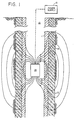
- a typical wellbore 10 is shown in Figure 1 lined with steel casing 11 and anchored by a sheath of cement 12 which is circumferentially bonded to both the casing 11 and the wall of the wellbore 13.
- An internal magnetizer shown schematically at 14, is lowered into the casing by means of a suitable wireline cable (not shown).
- the magnetizer core may preferably be of soft iron wound with a number of layers of copper wire.
- Power is supplied to the magnetizer from an uphole power supply 15.
- the power can be applied to the magnetizer continuously as a D.C. voltage or can be applied in unipolar pulses from a storage capicitor. When the polarity of the power to the magnetizer is reversed, a magnetic pole develops in the casing 11.
- the anomaly created by the magnetization of the casing 11 may be as illustrated in Figure 2 wherein a plurality of alternating N and S magnetic poles are spaced along the casing 11.
- the spacing L between such poles should be of sufficient distance to maximize the detection range of the casing from a relief well or other well into which a magnetometer is located.
- the monopole spacing L is much greater than the casing radius r.
- the desired magnetic field strength is created at a radial distance outward from the well casing at least equal to the distance between the magnetic flux leakage points.
- Figure 3 illustrates magnetic anomaly as a function of distance from the magnetized well casing for spaced magnetic monopoles of alternating polarity of 30 feet, 60 feet, 90 feet, 120 feet and 150 feet. It can be seen that as the spacing distance L between the monopoles is increased, the distance of detection of the anomaly from the well casing is increased. This is due to the fall of the magnetic field strength at the rate of 1/R where R is the distance from the magnetometer in the relief or other wellbore to the magnetized well casing 11 in the wellbore 10 for example.
- the internal magnetizer 14 was comprised of an 18 inch Armco soft iron core of 1 1/4 inch diameter with a two layer winding of #16 copper wire.
- a monopole magnetic pole strength of 1.8 x 10 5 alpha-ft 2 (on 1.8 x 10 3 cmu) was produced with a 30 volt D.C. pulse supplied to the magnetizer from the capacitive discharge of the uphole power supply.
- the casing could be magnetized on the earth's surface as it is being lowered into the wellbore.
- pulsed power may be utilized in magnetizing the casing in lieu of D.C. power.
- Figure 4 illustrates an alternate method for magnetizing the well casing in acocrdance with the invention.
- a current sonde 14 with releasable contact pads 15 and 16 is employed and is lowered through the casing 11 to a desired depth by means of the insulated cable 17.
- the pads 15 and 16 are equipped with current emitting electrodes which make contact with the well casing 11.
- Current supplied from the uphole power supply 22 passes through the sonde 14 and the contact pads 15 and 16 into the well casing 11 at the desired depth location. At this depth location about one-half the current flows up the casing 11 while about one-half the current flows down the casing 11 as illustrated in Figure 2. There is also a small leakage current to the formation per unit length of casing.
- the upward current flow in casing 11 subtracted from the cable current I generates a magnetic field H in a first direction about the casing while the downward current flow generates a magnetic field H' approximately equal to H in the same direction about the casing.
- a magnetometer located such as in a non-magnetic section of the drill string in a new well being drilled nearby.
- the current injection point should be as close to the likely intersection point between the two wells as possible. The further the injection point is from the desired depth point, the weaker the magnetic field will be at the desired depth point. If the current were injected at a point on the casing near the surface of the earth, the current would be attenuated rapidly with depth due to leakage through the surrounding formations. For example, with one ampere of current injected into the casing at the surface of the earth, about 1 0 -7 amperes would be flowing in the casing at a depth of about 10,000 feet. The magnetic field created at 10,000 feet is thus greatly reduced. However with one ampere of current injected at the 10,000 foot depth in accordance with the present invention, about one-half ampere of current will be flowing in each direction in the casing with a much larger resulting magnetic field.
- Either AC or DC current could be applied to the well casing to create the desired magnetic field.
- each of the producing wells may, for example, be injected with AC current of different frequencies so as to create differing detectable magnetic fields for each of the producing wells.
- the method of this invention may be used to locate a well so that a second well may be directionally drilled to intersect it.
- Figure 6 shows a blowout well 115 with wellbore 110 and a relief well 116 with wellbore 117 having a trajectory such that it intersects the wellbore 110 of the blowout well at a position near the bottom of the wellbore 110.
- Such an intersection near the bottom of the blowout well 110 permits the pumping of mud or cement from the relief well into the blowout well through the producing formation in order to kill the blowout.
- a flux gate magnetometer located near the bottom of the relief well being drilled senses for the magnetic anomaly provided by the previously magnetized casing of the blowout well as the directional drilling of the relief well approaches the desired intersection with the blowout well. This directional drilling is then redirected as necessary to the desired intersect location.
Landscapes
- Engineering & Computer Science (AREA)
- Physics & Mathematics (AREA)
- Life Sciences & Earth Sciences (AREA)
- Geology (AREA)
- Mining & Mineral Resources (AREA)
- General Life Sciences & Earth Sciences (AREA)
- Environmental & Geological Engineering (AREA)
- Remote Sensing (AREA)
- Electromagnetism (AREA)
- Geophysics (AREA)
- Geochemistry & Mineralogy (AREA)
- Fluid Mechanics (AREA)
- General Physics & Mathematics (AREA)
- Geophysics And Detection Of Objects (AREA)
- Earth Drilling (AREA)
- Details Of Garments (AREA)
- Magnetic Treatment Devices (AREA)
- Water Treatment By Electricity Or Magnetism (AREA)
Applications Claiming Priority (6)
| Application Number | Priority Date | Filing Date | Title |
|---|---|---|---|
| US42601982A | 1982-09-28 | 1982-09-28 | |
| US426028 | 1982-09-28 | ||
| US426019 | 1982-09-28 | ||
| US06/426,028 US4465140A (en) | 1982-09-28 | 1982-09-28 | Method for the magnetization of well casing |
| US06/426,030 US4458767A (en) | 1982-09-28 | 1982-09-28 | Method for directionally drilling a first well to intersect a second well |
| US426030 | 1982-09-28 |
Publications (2)
| Publication Number | Publication Date |
|---|---|
| EP0104854A2 true EP0104854A2 (fr) | 1984-04-04 |
| EP0104854A3 EP0104854A3 (fr) | 1985-04-10 |
Family
ID=27411497
Family Applications (1)
| Application Number | Title | Priority Date | Filing Date |
|---|---|---|---|
| EP83305478A Withdrawn EP0104854A3 (fr) | 1982-09-28 | 1983-09-19 | Procédé de magnétisation de la paroi d'un puits |
Country Status (3)
| Country | Link |
|---|---|
| EP (1) | EP0104854A3 (fr) |
| CA (1) | CA1228639A (fr) |
| NO (1) | NO159685C (fr) |
Cited By (9)
| Publication number | Priority date | Publication date | Assignee | Title |
|---|---|---|---|---|
| AU607522B2 (en) * | 1987-07-30 | 1991-03-07 | Shell Internationale Research Maatschappij B.V. | Method of magnetising well tubulars |
| WO1995019490A1 (fr) * | 1994-01-13 | 1995-07-20 | Shell Internationale Research Maatschappij B.V. | Procede de creation d'un trou de forage dans une formation terrestre |
| RU2232861C1 (ru) * | 2003-02-25 | 2004-07-20 | Закрытое акционерное общество "Инженерно-производственная фирма АСУ-нефть" | Способ предупреждения встречи стволов при кустовом бурении нефтяных и газовых скважин |
| RU2235844C1 (ru) * | 2003-02-25 | 2004-09-10 | Закрытое акционерное общество "Инженерно-производственная фирма АСУ-нефть" | Система предупреждения встречи стволов при кустовом бурении нефтяных и газовых скважин |
| WO2009029850A3 (fr) * | 2007-08-31 | 2009-05-14 | Baker Hughes Inc | Procédé et appareil pour mesurer la proximité d'un puits pendant le forage |
| RU2386810C2 (ru) * | 2004-11-30 | 2010-04-20 | Дженерал Электрик Компани | Способ и система для точного направления бурения двойных скважин |
| RU2468200C2 (ru) * | 2006-06-05 | 2012-11-27 | Халлибертон Энерджи Сервисиз, Инк. | Устройство измерения расстояния и определения направления между двумя буровыми скважинами (варианты), способ измерения расстояния и определения направления между двумя буровыми скважинами, узел соленоида устройства измерения расстояния и определения направления между двумя буровыми скважинами |
| RU2619952C2 (ru) * | 2012-12-21 | 2017-05-22 | Хэллибертон Энерджи Сервисиз, Инк. | Система и способы выполнения измерений дальности с применением привязки к третьей скважине |
| RU2669974C2 (ru) * | 2013-12-23 | 2018-10-17 | Хэллибертон Энерджи Сервисиз, Инк. | Способ и система магнитной дальнометрии и геонавигации |
Families Citing this family (1)
| Publication number | Priority date | Publication date | Assignee | Title |
|---|---|---|---|---|
| RU2405106C1 (ru) * | 2009-06-18 | 2010-11-27 | Государственное образовательное учреждение высшего профессионального образования Российский государственный университет нефти и газа им. И.М. Губкина | Система контроля процесса взаимного ориентирования стволов при кустовом бурении нефтяных и газовых скважин |
Family Cites Families (1)
| Publication number | Priority date | Publication date | Assignee | Title |
|---|---|---|---|---|
| US4443762A (en) * | 1981-06-12 | 1984-04-17 | Cornell Research Foundation, Inc. | Method and apparatus for detecting the direction and distance to a target well casing |
-
1983
- 1983-09-19 EP EP83305478A patent/EP0104854A3/fr not_active Withdrawn
- 1983-09-27 NO NO833476A patent/NO159685C/no not_active IP Right Cessation
- 1983-09-27 CA CA000437691A patent/CA1228639A/fr not_active Expired
Cited By (12)
| Publication number | Priority date | Publication date | Assignee | Title |
|---|---|---|---|---|
| AU607522B2 (en) * | 1987-07-30 | 1991-03-07 | Shell Internationale Research Maatschappij B.V. | Method of magnetising well tubulars |
| WO1995019490A1 (fr) * | 1994-01-13 | 1995-07-20 | Shell Internationale Research Maatschappij B.V. | Procede de creation d'un trou de forage dans une formation terrestre |
| US5541517A (en) * | 1994-01-13 | 1996-07-30 | Shell Oil Company | Method for drilling a borehole from one cased borehole to another cased borehole |
| AU684894B2 (en) * | 1994-01-13 | 1998-01-08 | Shell Internationale Research Maatschappij B.V. | Method of creating a borehole in an earth formation |
| RU2232861C1 (ru) * | 2003-02-25 | 2004-07-20 | Закрытое акционерное общество "Инженерно-производственная фирма АСУ-нефть" | Способ предупреждения встречи стволов при кустовом бурении нефтяных и газовых скважин |
| RU2235844C1 (ru) * | 2003-02-25 | 2004-09-10 | Закрытое акционерное общество "Инженерно-производственная фирма АСУ-нефть" | Система предупреждения встречи стволов при кустовом бурении нефтяных и газовых скважин |
| RU2386810C2 (ru) * | 2004-11-30 | 2010-04-20 | Дженерал Электрик Компани | Способ и система для точного направления бурения двойных скважин |
| RU2468200C2 (ru) * | 2006-06-05 | 2012-11-27 | Халлибертон Энерджи Сервисиз, Инк. | Устройство измерения расстояния и определения направления между двумя буровыми скважинами (варианты), способ измерения расстояния и определения направления между двумя буровыми скважинами, узел соленоида устройства измерения расстояния и определения направления между двумя буровыми скважинами |
| WO2009029850A3 (fr) * | 2007-08-31 | 2009-05-14 | Baker Hughes Inc | Procédé et appareil pour mesurer la proximité d'un puits pendant le forage |
| RU2619952C2 (ru) * | 2012-12-21 | 2017-05-22 | Хэллибертон Энерджи Сервисиз, Инк. | Система и способы выполнения измерений дальности с применением привязки к третьей скважине |
| RU2669974C2 (ru) * | 2013-12-23 | 2018-10-17 | Хэллибертон Энерджи Сервисиз, Инк. | Способ и система магнитной дальнометрии и геонавигации |
| US10294773B2 (en) | 2013-12-23 | 2019-05-21 | Halliburton Energy Services, Inc. | Method and system for magnetic ranging and geosteering |
Also Published As
| Publication number | Publication date |
|---|---|
| NO159685C (no) | 1989-01-25 |
| CA1228639A (fr) | 1987-10-27 |
| EP0104854A3 (fr) | 1985-04-10 |
| NO833476L (no) | 1984-03-29 |
| NO159685B (no) | 1988-10-17 |
Similar Documents
| Publication | Publication Date | Title |
|---|---|---|
| US4593770A (en) | Method for preventing the drilling of a new well into one of a plurality of production wells | |
| US4458767A (en) | Method for directionally drilling a first well to intersect a second well | |
| US4465140A (en) | Method for the magnetization of well casing | |
| US8113298B2 (en) | Wireline communication system for deep wells | |
| US9759060B2 (en) | Proximity detection system for deep wells | |
| US5074365A (en) | Borehole guidance system having target wireline | |
| US8810247B2 (en) | Electromagnetic orientation system for deep wells | |
| US4529939A (en) | System located in drill string for well logging while drilling | |
| US5485089A (en) | Method and apparatus for measuring distance and direction by movable magnetic field source | |
| US5676212A (en) | Downhole electrode for well guidance system | |
| US7475741B2 (en) | Method and system for precise drilling guidance of twin wells | |
| US8418782B2 (en) | Method and system for precise drilling guidance of twin wells | |
| US7656161B2 (en) | Magnetization of target well casing strings tubulars for enhanced passive ranging | |
| US9534488B2 (en) | Electromagnetic ranging source suitable for use in a drill string | |
| CA1228639A (fr) | Aimantation d'un tubage de forage | |
| Mallary et al. | Collision avoidance using a single wire magnetic ranging technique at Milne point, Alaska | |
| CA1237764A (fr) | Alimentation du tubage d'un forage |
Legal Events
| Date | Code | Title | Description |
|---|---|---|---|
| PUAI | Public reference made under article 153(3) epc to a published international application that has entered the european phase |
Free format text: ORIGINAL CODE: 0009012 |
|
| AK | Designated contracting states |
Designated state(s): DE GB NL |
|
| PUAL | Search report despatched |
Free format text: ORIGINAL CODE: 0009013 |
|
| AK | Designated contracting states |
Designated state(s): DE GB NL |
|
| 17P | Request for examination filed |
Effective date: 19850911 |
|
| 17Q | First examination report despatched |
Effective date: 19870317 |
|
| STAA | Information on the status of an ep patent application or granted ep patent |
Free format text: STATUS: THE APPLICATION HAS BEEN WITHDRAWN |
|
| 18W | Application withdrawn |
Withdrawal date: 19890727 |
|
| R18W | Application withdrawn (corrected) |
Effective date: 19890727 |
|
| RIN1 | Information on inventor provided before grant (corrected) |
Inventor name: HOEHN, GUSTAVE LEO, JR. |