EP0104862A1 - Production de tubes soudés - Google Patents
Production de tubes soudés Download PDFInfo
- Publication number
- EP0104862A1 EP0104862A1 EP83305495A EP83305495A EP0104862A1 EP 0104862 A1 EP0104862 A1 EP 0104862A1 EP 83305495 A EP83305495 A EP 83305495A EP 83305495 A EP83305495 A EP 83305495A EP 0104862 A1 EP0104862 A1 EP 0104862A1
- Authority
- EP
- European Patent Office
- Prior art keywords
- tube
- seam
- welding
- along
- deviation
- Prior art date
- Legal status (The legal status is an assumption and is not a legal conclusion. Google has not performed a legal analysis and makes no representation as to the accuracy of the status listed.)
- Withdrawn
Links
- 238000004519 manufacturing process Methods 0.000 title description 6
- 238000003466 welding Methods 0.000 claims abstract description 69
- 239000011324 bead Substances 0.000 claims abstract description 17
- 238000012544 monitoring process Methods 0.000 claims abstract description 17
- 238000000034 method Methods 0.000 claims abstract description 16
- 230000009471 action Effects 0.000 claims description 3
- 230000008569 process Effects 0.000 claims description 3
- 230000007246 mechanism Effects 0.000 claims description 2
- 239000002184 metal Substances 0.000 description 9
- 230000004907 flux Effects 0.000 description 3
- CWYNVVGOOAEACU-UHFFFAOYSA-N Fe2+ Chemical compound [Fe+2] CWYNVVGOOAEACU-UHFFFAOYSA-N 0.000 description 2
- 230000007547 defect Effects 0.000 description 2
- 238000006073 displacement reaction Methods 0.000 description 2
- 238000005096 rolling process Methods 0.000 description 2
- 230000008901 benefit Effects 0.000 description 1
- 230000015572 biosynthetic process Effects 0.000 description 1
- 238000010586 diagram Methods 0.000 description 1
- 238000003113 dilution method Methods 0.000 description 1
- 230000000694 effects Effects 0.000 description 1
- 239000000463 material Substances 0.000 description 1
- 230000003287 optical effect Effects 0.000 description 1
- 230000035515 penetration Effects 0.000 description 1
- 238000003303 reheating Methods 0.000 description 1
- 230000000007 visual effect Effects 0.000 description 1
Images

Classifications
-
- B—PERFORMING OPERATIONS; TRANSPORTING
- B23—MACHINE TOOLS; METAL-WORKING NOT OTHERWISE PROVIDED FOR
- B23K—SOLDERING OR UNSOLDERING; WELDING; CLADDING OR PLATING BY SOLDERING OR WELDING; CUTTING BY APPLYING HEAT LOCALLY, e.g. FLAME CUTTING; WORKING BY LASER BEAM
- B23K9/00—Arc welding or cutting
- B23K9/02—Seam welding; Backing means; Inserts
- B23K9/025—Seam welding; Backing means; Inserts for rectilinear seams
- B23K9/0253—Seam welding; Backing means; Inserts for rectilinear seams for the longitudinal seam of tubes
Definitions
- This invention relates to the production of welded tube and more particularly the production of longitudinally metallic welded tube of large diameter.
- One frequently used manner of manufacture of large ferrous (and non ferrous) metal tubes involves forming a metal plate into cylindrical form by a rolling operation, and then bringing together the edges along the tube to a usually 'V' shaped seam which is then subjected to a welding step, preferably by submerged arc welding, by which is meant an automatic flux shielded method of welding wherein the electrode wire is completely submerged beneath a flux.
- a problem experienced with this method of tube manufacture is that frequently, after rolling, the edges of the plate along the tube, although often substantially straight, are not parallel to the side walls of the cylinder formed by the rolled metal. This is a particular problem when dealing with heavy gauge plate. The problem arises not so much in relation to the misalignment of the edges of the plate to the axis of the tube, which does not effect the acceptability of the tube for all normal uses thereof, but in relation to the procedure of welding the seam.
- the welding operation is commonly carried out firstly by manually tack welding metal tabs to the extreme ends of the metallic cylinder bridging either side of the seam gap between adjacent edges, and then tack welding the edges together at intervals along the proposed weld line so as to provide a temporary fixing for the seam gap. Subsequently the welded seam along the tube is usually formed by mechanised welding.
- the mechanised welding system usually forms the weld along the tube in two stages .
- Clearly such a guiding arrangement is not possible for forming the external weld bead, and in practise this second stage of the system is normally accomplished by manual operation in which an operator by means of a control wheel or some such discipliner device guides the welder head and visually aligns it with the tube seam.
- This second stage commonly includes a welder head mounted on a carriage or sub-beam which travels along a straight beam parallel to the tube. Provision will also be included for traverse of the welder head to both sides during the sub-beams longitudinal travel.
- a method of welding a bead along the edges of metallic plate or strip formed into tube shape by means of a welder head movably carried by a beam disposed longitudinally to the tube comprising the steps of monitoring the deviation of the seam at a first point along the tube from a plane passing through or parallel to the tube axis, monitoring the deviation of the weld line from the same plane at a second position along the tube, computing from the data so acquired a deviation factor for the weld line along the tube, and applying a weld bead along the weld seam whilst monitoring the position of the welding head about the tube and at the same time producing a signal indicative of variations during welding between the transverse position of the welding head and the previously calculated deviation factor for that position along the tube.
- the invention is particularly applicable to forming the external bead along the weld seam, in which case a weld head support beam is disposed longitudinally above the tube, the movable welding head being carried therebelow.
- Means may be provided for correcting the position of the welder head in dependence on the error signal produced.
- a tube 1 is located beneath a beam 2 extending longitudinally to the tube 1 and adapted to carry a welding head on a sub-beam 5 movable along the beam for welding a seam 3 formed from adjacent edges of a plate from which the tube 1 has been rolled.
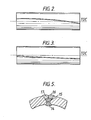
- the seam 3 is somewhat twisted and misaligned with respect to the centre line of the tube wall immediately beneath the beam 2.
- the line of the seams may lie to one side of and subtend a single angle with the welder beam centre line.At times it is possible for example as shown in Figure 2,that the extreme ends of the line at the tube ends lie to the left and right of the welder beam centre line respectively and the weld line is curved.
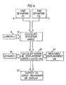
- variable m can be expressed for any pipe as: where D 2 is the distance of the seam from the welder at a predetermined distance L from the end of the tube.
- the distance L can be the tube's length.
- a linear motion transducer such as a linear potentiometer is fitted to the welder head travelling sub-beam 5 to provide a measure of the displacement of the welder head, and hence the weld seam, in a direction at right angles to the axis of the beam (2).
- a second linear transducer which may be a line or wire connected to the periphery of a resiliently urged drum carrying a pulse generator, is fitted to the welder head sub-beam 5, so that the longitudinal position of the welding head along the tube can be determined.
- Optical sighting means (not shown) are provided for the operator to accurately align the welding equipment with the weld seam.
- Welding then commences with the laying down of a weld bead within the weld seam from one end of the tube to the other.
- the difference between the actual position 11 of the welding head from the datum line in relation to its theoretical desired position in accordance with the deviation factor for that tube is computed at 12 and arranged to provide an error signal from which is calculated and initiated at 13, necessary corrective action to bring the welder head into line with the weld seam.
- the computed output can be applied to any suitable form of servo mechanism to provide fully automatic control to the welder head.
- any suitable form of servo mechanism to provide fully automatic control to the welder head.
- the amount and direction of corrective action required to keep the welder head accurately in line above the welder line can be displayed for information of an operator.
- Such an operator display can be in the form of a movable pointer, a digital readout, a graphic display, a line printer, a moving pen recorder or other suitable known means of electronic or electrical visual display.
- the invention can be applied to the operation and control of welding transversely of the tube where, for example, the tube is formed of more than one plate butted together to the configuration of the tube and welded together both along and transversely of the tube by the submerged arc system, for example.
- Figure 5 shows in cross section how a typical multipass weld would be laid down.
- the prewelded inner bead is shown at 14, and 15 represents the first external bead to be applied.
- welding control of external seam welding can be provided substantially overcoming the difficulties hereinbefore referred to.
- the arrangement of the present invention can be used for internal seam welding control. In this latter context the arrangement would be advantageous in overcoming difficulties of providing accurate weld head location at the extreme ends of the tube to be welded, as mentioned previously hereinabove.
Landscapes
- Engineering & Computer Science (AREA)
- Physics & Mathematics (AREA)
- Plasma & Fusion (AREA)
- Mechanical Engineering (AREA)
- Butt Welding And Welding Of Specific Article (AREA)
- Arc Welding In General (AREA)
Applications Claiming Priority (2)
| Application Number | Priority Date | Filing Date | Title |
|---|---|---|---|
| GB8226689 | 1982-09-20 | ||
| GB8226689 | 1982-09-20 |
Publications (1)
| Publication Number | Publication Date |
|---|---|
| EP0104862A1 true EP0104862A1 (fr) | 1984-04-04 |
Family
ID=10533025
Family Applications (1)
| Application Number | Title | Priority Date | Filing Date |
|---|---|---|---|
| EP83305495A Withdrawn EP0104862A1 (fr) | 1982-09-20 | 1983-09-19 | Production de tubes soudés |
Country Status (2)
| Country | Link |
|---|---|
| EP (1) | EP0104862A1 (fr) |
| GB (1) | GB2127178B (fr) |
Cited By (3)
| Publication number | Priority date | Publication date | Assignee | Title |
|---|---|---|---|---|
| US7984579B2 (en) | 2008-04-30 | 2011-07-26 | Taser International, Inc. | Systems and methods for electronic weaponry that detects properties of a unit for deployment |
| CN110385347A (zh) * | 2018-04-16 | 2019-10-29 | 福特汽车公司 | 对用于车身部件的挤压管进行径向定向的系统和方法 |
| CN112222690A (zh) * | 2020-09-30 | 2021-01-15 | 中石化第四建设有限公司 | 一种管道焊缝管理信息建立方法 |
Citations (7)
| Publication number | Priority date | Publication date | Assignee | Title |
|---|---|---|---|---|
| FR2059203A5 (fr) * | 1969-08-25 | 1971-05-28 | Smith Corp A O | |
| DE2647290A1 (de) * | 1976-10-20 | 1978-04-27 | Daimler Benz Ag | Verfahren und vorrichtung zur selbststeuerung eines werkzeuges entlang einer werkstueckgebundenen kontur |
| DE2741728A1 (de) * | 1977-09-16 | 1979-03-22 | Karlsruhe Augsburg Iweka | Verfahren zum identifizieren und optimieren mechanischer groessen |
| DE2840351A1 (de) * | 1977-09-20 | 1979-03-29 | Jean Peiffert | Verfahren und vorrichtung zum steuern bzw. regeln eines sich drehenden stuecks |
| EP0017167A1 (fr) * | 1979-03-28 | 1980-10-15 | Messer Griesheim Gmbh | Machine à souder pour joindre deux pièces métalliques |
| US4288020A (en) * | 1979-07-02 | 1981-09-08 | The Babcock & Wilcox Company | Tracking type welding apparatus |
| DE3143834A1 (de) * | 1980-11-17 | 1982-06-24 | Kabushiki Kaisha Komatsu Seisakusho, Tokyo | "korrektursystem fuer die bahnsteuerung eines schweissroboters" |
-
1983
- 1983-09-19 EP EP83305495A patent/EP0104862A1/fr not_active Withdrawn
- 1983-09-19 GB GB08324987A patent/GB2127178B/en not_active Expired
Patent Citations (7)
| Publication number | Priority date | Publication date | Assignee | Title |
|---|---|---|---|---|
| FR2059203A5 (fr) * | 1969-08-25 | 1971-05-28 | Smith Corp A O | |
| DE2647290A1 (de) * | 1976-10-20 | 1978-04-27 | Daimler Benz Ag | Verfahren und vorrichtung zur selbststeuerung eines werkzeuges entlang einer werkstueckgebundenen kontur |
| DE2741728A1 (de) * | 1977-09-16 | 1979-03-22 | Karlsruhe Augsburg Iweka | Verfahren zum identifizieren und optimieren mechanischer groessen |
| DE2840351A1 (de) * | 1977-09-20 | 1979-03-29 | Jean Peiffert | Verfahren und vorrichtung zum steuern bzw. regeln eines sich drehenden stuecks |
| EP0017167A1 (fr) * | 1979-03-28 | 1980-10-15 | Messer Griesheim Gmbh | Machine à souder pour joindre deux pièces métalliques |
| US4288020A (en) * | 1979-07-02 | 1981-09-08 | The Babcock & Wilcox Company | Tracking type welding apparatus |
| DE3143834A1 (de) * | 1980-11-17 | 1982-06-24 | Kabushiki Kaisha Komatsu Seisakusho, Tokyo | "korrektursystem fuer die bahnsteuerung eines schweissroboters" |
Non-Patent Citations (1)
| Title |
|---|
| Patent Abstracts of Japan Vol. 6, no. 48, 27 March 1982 & JP-A-56 163864 * |
Cited By (4)
| Publication number | Priority date | Publication date | Assignee | Title |
|---|---|---|---|---|
| US7984579B2 (en) | 2008-04-30 | 2011-07-26 | Taser International, Inc. | Systems and methods for electronic weaponry that detects properties of a unit for deployment |
| CN110385347A (zh) * | 2018-04-16 | 2019-10-29 | 福特汽车公司 | 对用于车身部件的挤压管进行径向定向的系统和方法 |
| CN112222690A (zh) * | 2020-09-30 | 2021-01-15 | 中石化第四建设有限公司 | 一种管道焊缝管理信息建立方法 |
| CN112222690B (zh) * | 2020-09-30 | 2022-08-30 | 中石化第四建设有限公司 | 一种管道焊缝管理信息建立方法 |
Also Published As
| Publication number | Publication date |
|---|---|
| GB8324987D0 (en) | 1983-10-19 |
| GB2127178A (en) | 1984-04-04 |
| GB2127178B (en) | 1986-06-25 |
Similar Documents
| Publication | Publication Date | Title |
|---|---|---|
| EP1077785B2 (fr) | Appareil et procede de soudage de tuyaux | |
| US4577796A (en) | Method and apparatus for tracking seam welds on pipes and the like | |
| EP2507006B1 (fr) | Poste de soudure et procédé permettant de poser des canalisations, les sections de tuyau étant soudées ensemble par un soudage interne et externe | |
| EP1335809B1 (fr) | Syst me automatique de pr sentation et de guidage de la t te de soudage et proc d correspondant | |
| US5534676A (en) | System for automatically controlling weld material beading in orbital welding processes for medium- and large-size pipes | |
| KR101220751B1 (ko) | 탠덤 아크 용접 시스템을 제어하는 로봇 컨트롤러, 그것을 이용한 아크 트래킹 제어 방법 및 탠덤 아크 용접 시스템 | |
| JP3079485B2 (ja) | 角鋼管の自動溶接装置 | |
| WO2007017306A1 (fr) | Procede de soudage a fente etroite sous flux en poudre au moyen d'une electrode oscillante | |
| CN108655537B (zh) | 一种机器人自动补偿焊接方法 | |
| GB2127178A (en) | Improvements in or relating to the production of welded tube | |
| JP4341172B2 (ja) | 多層盛溶接におけるトーチ位置の制御方法 | |
| EP1647350B1 (fr) | Installation et procédé de soudage laser ainsi que soudure laser | |
| JPH1058139A (ja) | 管交差部溶接方法 | |
| US20260138201A1 (en) | Adaptive welding | |
| EP0049037B1 (fr) | Méthode et dispositif pour le soudage à gorge étroite de tubes épais | |
| ITMI971511A1 (it) | Procedimento di inseguimento automatico del cianfrino per la saldatura di testa di tubi e apparecchiatura per la realizzazione | |
| EP1399287B1 (fr) | Procede de coupe au rayonnement laser de pieces a assembler | |
| JPH0866770A (ja) | 固定管の片面突合せ溶接における初層溶接方法 | |
| JPH0910938A (ja) | 固定鋼管の自動溶接方法 | |
| DE102012204207B4 (de) | Verfahren zum Laserstrahlschweißen | |
| JPH0459993B2 (fr) | ||
| JPH07328766A (ja) | 横向自動溶接方法 | |
| JPH03180275A (ja) | 片面溶接工法 | |
| JPS62259673A (ja) | 固定管の円周溶接方法 | |
| JPH05245636A (ja) | 消耗電極式アーク溶接方法 |
Legal Events
| Date | Code | Title | Description |
|---|---|---|---|
| PUAI | Public reference made under article 153(3) epc to a published international application that has entered the european phase |
Free format text: ORIGINAL CODE: 0009012 |
|
| AK | Designated contracting states |
Designated state(s): BE DE FR IT NL SE |
|
| 17P | Request for examination filed |
Effective date: 19841001 |
|
| STAA | Information on the status of an ep patent application or granted ep patent |
Free format text: STATUS: THE APPLICATION IS DEEMED TO BE WITHDRAWN |
|
| 18D | Application deemed to be withdrawn |
Effective date: 19851212 |
|
| RIN1 | Information on inventor provided before grant (corrected) |
Inventor name: PARKER, MICHAEL JOHN Inventor name: PROUTEN, STEPHEN |