EP0104867B1 - Bauelemente zur Abschirmung gegen Strahlung - Google Patents
Bauelemente zur Abschirmung gegen Strahlung Download PDFInfo
- Publication number
- EP0104867B1 EP0104867B1 EP83305518A EP83305518A EP0104867B1 EP 0104867 B1 EP0104867 B1 EP 0104867B1 EP 83305518 A EP83305518 A EP 83305518A EP 83305518 A EP83305518 A EP 83305518A EP 0104867 B1 EP0104867 B1 EP 0104867B1
- Authority
- EP
- European Patent Office
- Prior art keywords
- core
- panel
- flanges
- panels
- cores
- Prior art date
- Legal status (The legal status is an assumption and is not a legal conclusion. Google has not performed a legal analysis and makes no representation as to the accuracy of the status listed.)
- Expired
Links
- 230000005855 radiation Effects 0.000 title claims abstract description 16
- 239000003365 glass fiber Substances 0.000 claims abstract description 13
- 239000000945 filler Substances 0.000 claims abstract description 9
- 239000000463 material Substances 0.000 claims description 11
- 239000000835 fiber Substances 0.000 claims description 4
- 230000014759 maintenance of location Effects 0.000 claims description 2
- 239000011162 core material Substances 0.000 claims 12
- 229920005989 resin Polymers 0.000 abstract description 5
- 239000011347 resin Substances 0.000 abstract description 5
- 239000011152 fibreglass Substances 0.000 abstract 1
- 230000006378 damage Effects 0.000 description 2
- 239000004033 plastic Substances 0.000 description 2
- 229920003023 plastic Polymers 0.000 description 2
- 239000004793 Polystyrene Substances 0.000 description 1
- 208000027418 Wounds and injury Diseases 0.000 description 1
- 239000002131 composite material Substances 0.000 description 1
- 238000010276 construction Methods 0.000 description 1
- 150000002118 epoxides Chemical class 0.000 description 1
- 208000014674 injury Diseases 0.000 description 1
- 238000000034 method Methods 0.000 description 1
- 230000004048 modification Effects 0.000 description 1
- 238000012986 modification Methods 0.000 description 1
- 229920002223 polystyrene Polymers 0.000 description 1
- 229920003002 synthetic resin Polymers 0.000 description 1
- 239000000057 synthetic resin Substances 0.000 description 1
Images

Classifications
-
- G—PHYSICS
- G21—NUCLEAR PHYSICS; NUCLEAR ENGINEERING
- G21C—NUCLEAR REACTORS
- G21C19/00—Arrangements for treating, for handling, or for facilitating the handling of, fuel or other materials which are used within the reactor, e.g. within its pressure vessel
- G21C19/02—Details of handling arrangements
- G21C19/06—Magazines for holding fuel elements or control elements
-
- G—PHYSICS
- G21—NUCLEAR PHYSICS; NUCLEAR ENGINEERING
- G21C—NUCLEAR REACTORS
- G21C11/00—Shielding structurally associated with the reactor
- G21C11/02—Biological shielding ; Neutron or gamma shielding
- G21C11/028—Biological shielding ; Neutron or gamma shielding characterised by the form or by the material
-
- G—PHYSICS
- G21—NUCLEAR PHYSICS; NUCLEAR ENGINEERING
- G21F—PROTECTION AGAINST X-RADIATION, GAMMA RADIATION, CORPUSCULAR RADIATION OR PARTICLE BOMBARDMENT; TREATING RADIOACTIVELY CONTAMINATED MATERIAL; DECONTAMINATION ARRANGEMENTS THEREFOR
- G21F3/00—Shielding characterised by its physical form, e.g. granules, or shape of the material
-
- E—FIXED CONSTRUCTIONS
- E04—BUILDING
- E04B—GENERAL BUILDING CONSTRUCTIONS; WALLS, e.g. PARTITIONS; ROOFS; FLOORS; CEILINGS; INSULATION OR OTHER PROTECTION OF BUILDINGS
- E04B1/00—Constructions in general; Structures which are not restricted either to walls, e.g. partitions, or floors or ceilings or roofs
- E04B1/62—Insulation or other protection; Elements or use of specified material therefor
- E04B1/92—Protection against other undesired influences or dangers
- E04B2001/925—Protection against harmful electro-magnetic or radio-active radiations, e.g. X-rays
-
- Y—GENERAL TAGGING OF NEW TECHNOLOGICAL DEVELOPMENTS; GENERAL TAGGING OF CROSS-SECTIONAL TECHNOLOGIES SPANNING OVER SEVERAL SECTIONS OF THE IPC; TECHNICAL SUBJECTS COVERED BY FORMER USPC CROSS-REFERENCE ART COLLECTIONS [XRACs] AND DIGESTS
- Y02—TECHNOLOGIES OR APPLICATIONS FOR MITIGATION OR ADAPTATION AGAINST CLIMATE CHANGE
- Y02E—REDUCTION OF GREENHOUSE GAS [GHG] EMISSIONS, RELATED TO ENERGY GENERATION, TRANSMISSION OR DISTRIBUTION
- Y02E30/00—Energy generation of nuclear origin
- Y02E30/30—Nuclear fission reactors
Definitions
- This invention relates generally to a radiation shielding assembly of the type comprising a plurality of panels each comprising a core of radiation shielding material, and fibre layers surrounding said core, the panels being located in edge to edge contact with their respective flanges releasably connected by fastener means.
- each panel has at least one flange extending in a plane generally normal to the plane of the core, the flanges being in contact and connected by said fastener means
- each panel includes a filler sheet extending generally parallel to and in sandwiched relation to the core and the fibre layers, which are glass fibre layers, the filler sheet being of a smaller area than the core and disposed on the opposite side thereof to the flanges so as to leave a recess in the face of the panel around the edge thereof and overlying the core, an auxiliary panel incorporating a core of radiation shielding materials being located in the depression formed by adjacent edgewise recesses so as to be substantially flush with the face of the panels, whereby said auxiliary panel overlaps the junction of the cores of adjacent panels.
- such components typically may have flanges formed of the same glass fibre material as is used adjacent the cores, and such flanges are interconnected as by removable fasteners, to bring the shielding cores of adjacent units into proximity to one another.
- an auxiliary panel or panels including radiation shielding material, is then attached in bridging relation with the flange connected units to provide a flush surface wall or enclosure.
- filler material such as plastics may be sandwiched in each unit, to provide a recess or recesses to receive the auxiliary panel.
- the auxiliary panel may have L-shaped cross section to provide a corner for the enclosure.
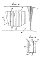
- a radiation shielding structural component comprises a longitudinally elongated body 10 having portion or portions of L-shaped cross section in lateral planes normal to the longitudinal direction. As is clear in Fig. 1, there may be two such L-shaped cross section portions associated with each body 10, one at each lateral end portion thereof.
- Each body 10 includes a panel or sheet shaped core 11 of radiation shielding material such as lead, the radiation to be protected against being a, 13 or y radiation. Core 11 extends both laterally (see arrows 12) and longitudinally (see arrows 13, and has thickness "t,".
- the body 10 also includes glass fiber layers surrounding the core and attached thereto as by suitable synthetic resins (epoxide, for example), such resins also impregnating the glass fiber material.
- layers 14 and 15 extend at the inner and outer sides of the core, with sub-layers 15a extending adjacent the outer side of core lateral end extents 11a, merging with layer 14 at the lateral ends 16 (see Fig. 2).
- the glass fiber layers are applied to the core in such a manner as to also provide glass fiber flanges 17 extending in planes generally normal to the plane of core 11, the like flanges located at laterally opposite ends of the core and merging with layers 14 and 16.
- a rigid laminate is formed, with the flanges rigidly attached.
- Figs. 2 and 5 show the use of the flanges of adjacent units, which abut one another at 19 and are laterally bored at 18 to receive removable fasteners such as bolts 20 having heads 20a and shanks 20b, and nuts on the threaded shanks.
- This brings the cores 11 of adjacent units in lateral end proximity, but separated by the glass fiber ends 16.
- an auxiliary panel 24 is located in bridging relation to the core end extents 11a, and adjacent glass fiber sub-layers 15a, i.e. at the outer sides of the bodies 10.
- Panel 24 also contains a laterally and longitudinally extending core sheet 25 of radiation shielding material, such as lead, which bridges the core and extents 11a, so that radiation cannot pass through the assembly.
- Glass fibre and resin layers 26 and 27 are bonded to opposite sides of core 25, providing a composite of thickness "t 2 " which approximates the depth of a recess 29 that receives the auxiliary panel.
- Recess 29 is formed by the inter-connected bodies, so that the outer surface of the auxiliary panel is substantially flush with the surfaces of the glass fiber sub-layers 15b associated with bodies 10.
- Sub-layers 15b are spaced outwardly from the cores 11 to cover and attach to filler sheets 31 extending in parallel sandwiched relation to or with the cores 11.
- Filler sheets 31 typically consists of lightweight plastics material such as polystyrene, for example.
- Sub-layers 15b merge with sub-layers 15a, at the stepped locations 15c adjacent the ends of filler sheets 31.
- Auxiliary panel 24 may be pressed into position, with slight interference with the shoulders 15d, or may be bonded to those shoulders or to sub-layers 15a.
- Fig. 3 is similar to Fig. 2, but shows an alternative method of retaining the auxiliary panel 24 in position.
- Panel 24 incorporates a web 38 that projects between the flanges 16, for removable fastener retention.
- Web 38 may consist of molded glass fibers and resin.
Landscapes
- Engineering & Computer Science (AREA)
- Physics & Mathematics (AREA)
- High Energy & Nuclear Physics (AREA)
- General Engineering & Computer Science (AREA)
- Plasma & Fusion (AREA)
- Biomedical Technology (AREA)
- General Health & Medical Sciences (AREA)
- Molecular Biology (AREA)
- Life Sciences & Earth Sciences (AREA)
- Health & Medical Sciences (AREA)
- Laminated Bodies (AREA)
- Materials For Medical Uses (AREA)
- Radiation-Therapy Devices (AREA)
- Building Environments (AREA)
Claims (4)
Priority Applications (1)
| Application Number | Priority Date | Filing Date | Title |
|---|---|---|---|
| AT83305518T ATE31992T1 (de) | 1982-09-28 | 1983-09-20 | Bauelemente zur abschirmung gegen strahlung. |
Applications Claiming Priority (2)
| Application Number | Priority Date | Filing Date | Title |
|---|---|---|---|
| US425724 | 1982-09-28 | ||
| US06/425,724 US4514640A (en) | 1982-09-28 | 1982-09-28 | Radiation shielding structures |
Publications (2)
| Publication Number | Publication Date |
|---|---|
| EP0104867A1 EP0104867A1 (de) | 1984-04-04 |
| EP0104867B1 true EP0104867B1 (de) | 1988-01-13 |
Family
ID=23687766
Family Applications (1)
| Application Number | Title | Priority Date | Filing Date |
|---|---|---|---|
| EP83305518A Expired EP0104867B1 (de) | 1982-09-28 | 1983-09-20 | Bauelemente zur Abschirmung gegen Strahlung |
Country Status (4)
| Country | Link |
|---|---|
| US (1) | US4514640A (de) |
| EP (1) | EP0104867B1 (de) |
| AT (1) | ATE31992T1 (de) |
| DE (1) | DE3375343D1 (de) |
Families Citing this family (23)
| Publication number | Priority date | Publication date | Assignee | Title |
|---|---|---|---|---|
| US4729869A (en) * | 1986-08-04 | 1988-03-08 | Combustion Engineering, Inc. | Modular radiation shielding system |
| NL1001051C2 (nl) * | 1995-08-24 | 1997-02-25 | Intos Interieurmakers B V | Afschermwand. |
| US6051185A (en) * | 1996-12-18 | 2000-04-18 | Sterigenics International | Apparatus for performing gamma irradiation |
| US6448571B1 (en) | 2000-08-15 | 2002-09-10 | James A. Goldstein | Radiation protection system |
| US20040176668A1 (en) * | 2000-08-15 | 2004-09-09 | Goldstein James A. | Support and sensing apparatus |
| FR2813702B1 (fr) * | 2000-09-01 | 2002-12-20 | Lemer Pax | Materiau de construction de structure radioprotectrice, structure radioprotectrice obtenue et procede de realisation |
| RU2192056C2 (ru) * | 2001-03-28 | 2002-10-27 | Тюняев Владимир Николаевич | Устройство для защиты от излучения (варианты) |
| EP1477991B1 (de) * | 2003-05-12 | 2008-03-26 | GE Inspection Technologies GmbH | Strahlenschutzkabine für eine Röntgenvorrichtung |
| FR2865571B1 (fr) * | 2004-01-23 | 2006-04-28 | Cogema Logistics | Dispositif de rangement prevu pour etre place dans un emballage destine au transport de matieres radioactives |
| DE102004004842B4 (de) * | 2004-01-30 | 2009-01-15 | Siemens Ag | Einrichtung zum Aufbau und zur Systemprüfung von Röntgenanlagen |
| US7057194B2 (en) * | 2004-04-07 | 2006-06-06 | Eco Cath-Lab Systems, Inc. | Radiation barrier |
| US7291854B2 (en) * | 2005-07-18 | 2007-11-06 | Trinity Health Corporation | Radiation attenuation corridor |
| US7829873B2 (en) * | 2006-07-28 | 2010-11-09 | Eco Cath-Lab Systems, Inc. | Lower shield for radiation protection system |
| US20100212243A1 (en) * | 2009-02-20 | 2010-08-26 | David Allen Lesoine | Lead sheet suspension stud |
| US20110272605A1 (en) * | 2010-05-10 | 2011-11-10 | Cohen Todd J | Shielded surgical garment |
| CN102733542A (zh) * | 2012-06-06 | 2012-10-17 | 中国电子科技集团公司第二十八研究所 | 一种x射线防护复合大板及其制成的机动式防护方舱 |
| JP6614633B2 (ja) * | 2013-12-27 | 2019-12-04 | 積水樹脂プラメタル株式会社 | 放射線遮蔽パネル及びそれを用いた塀 |
| JP6370078B2 (ja) * | 2014-03-26 | 2018-08-08 | 株式会社熊谷組 | 放射線遮蔽目地構造 |
| JP6384713B2 (ja) * | 2014-07-01 | 2018-09-05 | 清水建設株式会社 | 放射線遮蔽壁 |
| US10600522B2 (en) * | 2017-04-10 | 2020-03-24 | United States Of America As Represented By The Administrator Of Nasa | Method of making thin atomic (Z) grade shields |
| US11274464B2 (en) * | 2018-09-13 | 2022-03-15 | Baker Engineering & Risk Consultants, Inc. | Fragment-, overpressure-, radiation-, and toxic-resistant emergency safety shelter |
| EP4189187A4 (de) * | 2020-07-30 | 2025-06-18 | Lefkus, John | Bauelemente und strukturen mit materialien mit abschirmeigenschaften |
| CN113323173B (zh) * | 2021-05-26 | 2022-09-20 | 中国建筑第八工程局有限公司 | 泄压洞口错位防护装置 |
Family Cites Families (12)
| Publication number | Priority date | Publication date | Assignee | Title |
|---|---|---|---|---|
| US2858451A (en) * | 1955-03-07 | 1958-10-28 | Herman I Silversher | Laminar ray shielding materials |
| US3134020A (en) * | 1961-01-24 | 1964-05-19 | Shoenfeld Harold | Radiation protective panels |
| US3299270A (en) * | 1965-11-18 | 1967-01-17 | Avella Benjamin A D | Radiation-proof strip for wall and ceiling panel having a groove formed by two bifurcations |
| US4041872A (en) * | 1971-09-10 | 1977-08-16 | The United States Of America As Represented By The Secretary Of The Army | Wrapper, structural shielding device |
| DE2327939A1 (de) * | 1973-06-01 | 1974-12-19 | Byggmekanisering Ab | Plattenbauelement zur herstellung einer abschirmung gegen strahlung sowie daraus hergestellte abschirmungen |
| US4006362A (en) * | 1975-11-17 | 1977-02-01 | Brooks & Perkins, Incorporated | Shroud for storing radioactive spent nuclear fuel cells |
| FR2443121A1 (fr) * | 1978-02-09 | 1980-06-27 | Pillot Alain | Cloisons modulaires autoprotegees |
| EP0027290A3 (de) * | 1979-10-10 | 1982-04-14 | Baeten N.V. | Hochfrequenz-Abschirmplatte, Aufbau mit solchen Platten und Verfahren zu deren Herstellung |
| US4342620A (en) * | 1980-04-21 | 1982-08-03 | Combustion Engineering, Inc. | Box insert for storage of spent nuclear fuel assembly |
| US4382060A (en) * | 1980-05-22 | 1983-05-03 | Joseph Oat Corporation | Radioactive fuel cell storage rack |
| US4400623A (en) * | 1981-01-02 | 1983-08-23 | Nuclear Power Outfitters | Radiation attenuation system |
| DE3270164D1 (en) * | 1981-12-22 | 1986-04-30 | Westinghouse Electric Corp | Storage rack for spent bwr fuel assemblies |
-
1982
- 1982-09-28 US US06/425,724 patent/US4514640A/en not_active Expired - Fee Related
-
1983
- 1983-09-20 AT AT83305518T patent/ATE31992T1/de not_active IP Right Cessation
- 1983-09-20 EP EP83305518A patent/EP0104867B1/de not_active Expired
- 1983-09-20 DE DE8383305518T patent/DE3375343D1/de not_active Expired
Also Published As
| Publication number | Publication date |
|---|---|
| EP0104867A1 (de) | 1984-04-04 |
| ATE31992T1 (de) | 1988-01-15 |
| US4514640A (en) | 1985-04-30 |
| DE3375343D1 (en) | 1988-02-18 |
Similar Documents
| Publication | Publication Date | Title |
|---|---|---|
| EP0104867B1 (de) | Bauelemente zur Abschirmung gegen Strahlung | |
| EP0059735B1 (de) | Hybride zusammengesetzte strukturen | |
| EP0695232B1 (de) | Ineinandergreifende gerippte bauelemente | |
| US4910065A (en) | Reinforced honeycomb core sandwich panels and method for making same | |
| US4806703A (en) | Panel system for EMI shielded enclosures | |
| JPH0239920A (ja) | 特に航空機胴体用フレーム及びその製造方法 | |
| EP0373729A3 (de) | Verfahren zur Verstärkung einer Platte | |
| DE3774014D1 (de) | Thermoplastisches verbundmaterial. | |
| EP0389978A3 (de) | Mehrschichtplatte | |
| US3868297A (en) | A structural panel including a honeycomb core and a foamed polymer composition | |
| EP0584041A1 (de) | Profilkantleiste | |
| EP1573141B1 (de) | Grosse verbundkonstruktionen und verfahren zur herstellung grosser verbundkonstruktionen | |
| NZ229367A (en) | Composite laminated structures (e.g. trays) comprising a thermoplastic core layer with at least one outer layer on each side of the core comprising polyethylene terephthalate containing 10-60% of glass flake | |
| US3299270A (en) | Radiation-proof strip for wall and ceiling panel having a groove formed by two bifurcations | |
| US7700174B2 (en) | Laminate with fill layer | |
| US6668515B2 (en) | Composite joint for fitting at least one external member to a sandwich panel and panel integrating at least one such joint | |
| CA2107710A1 (en) | Method of producing a corrugated board as well as a corrugated board | |
| JPH05116267A (ja) | インサート付サンドイツチ板の製造方法 | |
| FI854015A0 (fi) | Laettkonstruktionskaerna, samt med denna laettkonstruktionskaerna utrustad kompositkonstruktionsdetalj, saerskilt en skida. | |
| CA2484393A1 (en) | Flat wall panel at least substantially made of cellulose material | |
| JPH0885178A (ja) | ハニカムサンドイッチパネル | |
| EP0027290A2 (de) | Hochfrequenz-Abschirmplatte, Aufbau mit solchen Platten und Verfahren zu deren Herstellung | |
| PT1303003E (pt) | Cobertura de protecção para sistemas de rádio, componentes para a mesma, assim como o respectivo processo de produção | |
| GB2117964A (en) | Radiation shielding bricks | |
| DE3042644A1 (de) | De- und remontierbare waermedaemmung, insbesondere fuer nukleare anlagen |
Legal Events
| Date | Code | Title | Description |
|---|---|---|---|
| PUAI | Public reference made under article 153(3) epc to a published international application that has entered the european phase |
Free format text: ORIGINAL CODE: 0009012 |
|
| AK | Designated contracting states |
Designated state(s): AT BE CH DE FR GB IT LI NL SE |
|
| 17P | Request for examination filed |
Effective date: 19840928 |
|
| GRAA | (expected) grant |
Free format text: ORIGINAL CODE: 0009210 |
|
| AK | Designated contracting states |
Kind code of ref document: B1 Designated state(s): AT BE CH DE FR GB IT LI NL SE |
|
| PG25 | Lapsed in a contracting state [announced via postgrant information from national office to epo] |
Ref country code: NL Effective date: 19880113 Ref country code: LI Effective date: 19880113 Ref country code: IT Free format text: LAPSE BECAUSE OF FAILURE TO SUBMIT A TRANSLATION OF THE DESCRIPTION OR TO PAY THE FEE WITHIN THE PRESCRIBED TIME-LIMIT;WARNING: LAPSES OF ITALIAN PATENTS WITH EFFECTIVE DATE BEFORE 2007 MAY HAVE OCCURRED AT ANY TIME BEFORE 2007. THE CORRECT EFFECTIVE DATE MAY BE DIFFERENT FROM THE ONE RECORDED. Effective date: 19880113 Ref country code: CH Effective date: 19880113 Ref country code: BE Effective date: 19880113 Ref country code: AT Effective date: 19880113 |
|
| REF | Corresponds to: |
Ref document number: 31992 Country of ref document: AT Date of ref document: 19880115 Kind code of ref document: T |
|
| PG25 | Lapsed in a contracting state [announced via postgrant information from national office to epo] |
Ref country code: SE Effective date: 19880131 |
|
| REF | Corresponds to: |
Ref document number: 3375343 Country of ref document: DE Date of ref document: 19880218 |
|
| REG | Reference to a national code |
Ref country code: CH Ref legal event code: PL |
|
| ET | Fr: translation filed | ||
| NLV1 | Nl: lapsed or annulled due to failure to fulfill the requirements of art. 29p and 29m of the patents act | ||
| PLBE | No opposition filed within time limit |
Free format text: ORIGINAL CODE: 0009261 |
|
| STAA | Information on the status of an ep patent application or granted ep patent |
Free format text: STATUS: NO OPPOSITION FILED WITHIN TIME LIMIT |
|
| 26N | No opposition filed | ||
| PG25 | Lapsed in a contracting state [announced via postgrant information from national office to epo] |
Ref country code: GB Effective date: 19890920 |
|
| GBPC | Gb: european patent ceased through non-payment of renewal fee | ||
| PG25 | Lapsed in a contracting state [announced via postgrant information from national office to epo] |
Ref country code: FR Effective date: 19900531 |
|
| REG | Reference to a national code |
Ref country code: FR Ref legal event code: ST |
|
| PG25 | Lapsed in a contracting state [announced via postgrant information from national office to epo] |
Ref country code: DE Effective date: 19910101 |