EP0104919B1 - Méthodes d'enregistrement thermomagnétiques - Google Patents
Méthodes d'enregistrement thermomagnétiques Download PDFInfo
- Publication number
- EP0104919B1 EP0104919B1 EP19830305715 EP83305715A EP0104919B1 EP 0104919 B1 EP0104919 B1 EP 0104919B1 EP 19830305715 EP19830305715 EP 19830305715 EP 83305715 A EP83305715 A EP 83305715A EP 0104919 B1 EP0104919 B1 EP 0104919B1
- Authority
- EP
- European Patent Office
- Prior art keywords
- layer
- point
- magnetic field
- recording
- bit
- Prior art date
- Legal status (The legal status is an assumption and is not a legal conclusion. Google has not performed a legal analysis and makes no representation as to the accuracy of the status listed.)
- Expired
Links
Images




Classifications
-
- G—PHYSICS
- G11—INFORMATION STORAGE
- G11C—STATIC STORES
- G11C19/00—Digital stores in which the information is moved stepwise, e.g. shift registers
- G11C19/02—Digital stores in which the information is moved stepwise, e.g. shift registers using magnetic elements
- G11C19/08—Digital stores in which the information is moved stepwise, e.g. shift registers using magnetic elements using thin films in plane structure
- G11C19/0858—Generating, replicating or annihilating magnetic domains (also comprising different types of magnetic domains, e.g. "Hard Bubbles")
-
- G—PHYSICS
- G11—INFORMATION STORAGE
- G11C—STATIC STORES
- G11C13/00—Digital stores characterised by the use of storage elements not covered by groups G11C11/00, G11C23/00, or G11C25/00
- G11C13/04—Digital stores characterised by the use of storage elements not covered by groups G11C11/00, G11C23/00, or G11C25/00 using optical elements ; using other beam accessed elements, e.g. electron or ion beam
- G11C13/06—Digital stores characterised by the use of storage elements not covered by groups G11C11/00, G11C23/00, or G11C25/00 using optical elements ; using other beam accessed elements, e.g. electron or ion beam using magneto-optical elements
Definitions
- thermomagnetic recording methods This invention relates to thermomagnetic recording methods.
- thermomagnetic recording methods make use of bit recording methods in which recording is carried out by focussing a laser beam.
- bit recording methods include the Curie temperature recording method and the temperature compensation point recording method. With these methods, bits can be formed when the laser beams are incident on a recording medium.
- the bits are unstable and recorded bits may disappear if the - magnetic wall coercive force is low. Therefore, a high magnetic wall coercive force is required to retain the recorded information bits.
- the publication also reports that the bits were stable even if an external magnetic field of 0 Oe or a relatively intense magnetic field, such as 280 to 350 Oe, was applied to an amorphous GdCo thin film prepared by this method.
- an amorphous GdCo thin film stable bit information cannot be held unless the film has a relatively high coercive force. Since the magnetic wall coercive force is relatively high and the film quality is not uniform, the formation of bits of uniform diameter is difficult.
- the output of the laser must be controlled, as a result of which the laser has to have a complex structure.
- MnBi is most preferable since the recording density is high and the angle of magnetic polarisation is great.
- MnBi has a Curie temperature as high as 360°C and requires more energy for recording.
- the decomposition temperature is as low as 450°C, providing only a slight difference from the Curie temperature.
- MnBi thin film has low weathering or weather resistance and is easily damaged by a humid atmosphere.
- MnBi has a coercive force of 1.5 kOe and requires a magnetic field of 700 Oe for erasing the information.
- a separate device is required to induce such a high magnetic field for erasing the recorded information. This adversely affects the size of the device.
- an Mn-Cu-Bi alloy having a low Curie temperature of 200°C has a coercive force as high as 1.5 kOe.
- the diameter of the bit varies with the output of the laser. In other words, the greater the pulse width of the laser beam, the greater the diameter of the bit. This results in degradation in recording sensitivity and impairs high-density recording.
- thermomagnetic recording method comprising the steps of:
- Thermomagnetic recording methods embodying the invention and described hereinbelow incorporate the following advantageous features. They use a magnetic recording layer of low coercive force, a recording signal bit is recorded at a desired position on a magnetic recording layer and is held therein stably, a high density recording can be achieved independently of laser power, laser beam diameter or pulse width, and the recorded bits are formed with low power.
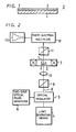
- a magnetic record or recording medium 3 comprises a film or layer 2 epitaxially grown on a crystal substrate 1 which is, for example, of non-magnetic rare-earth gallium garnet such as gadolinium gallium garnet (GGG).
- the film or layer 2 is made of soft magnetic material, has a strong uniaxial magnetic anistropy normal to. the surface of the layer, and has an axis of easy magnetisation normal to the surface of the layer.
- the layer 2 may, for example, comprise a YSmCaFeGe-system garnet layer such as (YSmCa) 3 (FeGe) 5 0 12 .
- a soft characteristic of the soft magnetic material layer 2 having an easy axis of magnetisation normal to the surface of the layer should be selected so as to allow the diameter of a recorded bit to be determined in practice only by a bias magnetic field when the layer is applied to the substrate 1 to form the magnetic record medium 3. It is desirable for the coercive force thereof to be selected to be lower than about 3 Oe and, more preferably still, lower than about 1 Oe.
- thermomagnetic recording using the above-described layer 2 of soft magnetic material having an easy axis of magnetisation normal to the layer can be carried out as follows. First, a bias magnetic field of predetermined strength is applied to the layer 2 of soft magnetic material having an easy axis of magnetisation normal to the layer so as to cause the layer to adopt a state in which the whole surface thereof has a single magnetic domain and, also, magnetisation is generated in a direction perpendicular to the surface of the layer. While the layer 2 is in this state, an optical or light beam is focussed on the surface of the layer and the light beam thus absorbed is converted to heat so that the temperature rises locally, thereby to form a magnetic domain of opposite direction to the bias magnetic field. A bit is thus written therein or recorded thereon. The recorded bit is a bubble domain and has a predetermined diameter. Also, the direction of magnetisation is opposite to that of the bias magnetic field.
- the strength of the bias magnetic field applied to put the layer of soft magnetic material into the state having a single magnetic domain over the whole visual field may vary in accordance with the nature of the layer of soft magnetic material employed, but it is sufficient that the strength thereof is selected to be in a range between a run-out field (the magnetic bubble domain tends to adopt a linear shape) H 2 and a collapse field (no magnetic bubble domain appears) H o .
- the strength of the bias magnetic field is selected to be in a range from 57 Oe to 73 Oe.
- the selected bias magnetic field to be applied may naturally be small.
- a compact-sized bias magnetic field generating apparatus may be sufficient, whereby a solenoid coil, a rubber magnet and so on can be used.
- the intensity of the incident light of the optical beam pulse may be selected to be in the range of from approximately 1 to about 100 mW, and the pulse width may be selected to be in a range of from approximately 0.1 to about 100 microseconds. Then, if an optical beam having the above incident light intensity and pulse width is introduced into the layer, the form of the recorded bit can be made substantially perfectly cylindrical.
- the bit information once recorded, can be erased by applying to the layer 2 a magnetic field which has a strength greater than the collapse magnetic field H o . And, since the collapse magnetic field H o of the layer of soft magnetic material, having an easy axis of magnetisation normal to the layer, is quite small, there is then an advantage that the recorded bit information can be erased with ease.
- the signal thus recorded can be read out or reproduced by using a magneto-optical effect.
- An example of a method of reproducing the recorded signal will now be described.
- Light such as Ar (argon) laser light and so on is polarised by a polariser to become linearly polarised light.
- the linearly polarised light is passed through a beam splitter and then converged or focussed by an objective lens onto the layer of soft magnetic material in which the recorded signal is written.
- the converged light beam is supplied through the layer to an analyser or reflected by a reflective film or layer deposited on the layer of soft magnetic material, refracted perpendicularly by the beam splitter and then supplied to the analyser.
- the linearly polarised light beam is subjected to Faraday rotation in a clockwise or anticlockwise direction in response to the magnetisation direction of the magnetic bubble domains existing in the layer of soft magnetic material.
- the light beam derived from an output side of the analyser is modulated in pulse width in response to the distance between the bits.
- the modulated light signal thus obtained is supplied to a photo-electric conversion device, such as a photodiode and so on, converted to an electrical signal, and supplied to (for example) a frequency modulated (FM) reproducing apparatus and reproduced.
- Reproduction is also possible according to a method involving coding at equal intervals.
- thermomagnetic recording method embodying the present invention the temperature of the layer of soft magnetic material is raised by irradiation by an optical beam pulse and a magnetic bubble domain having a direction opposite to the bias magnetic field is formed in the layer of the demagnetising field. Further, in order to effect a more stable recording, a layer of soft magnetic material having an easy axis of magnetisation normal to the surface of the layer is selected.
- the heating due to the irradiating light beam causes a temperature gradient in which the temperature is a maximum at the centre of the beam and becomes gradually lower as the periphery of the optical beam is approached.
- the magnetic characteristic of the layer has temperature dependency, the magnetic characteristic has a gradient corresponding to the temperature gradient.
- the direction of the force which the bit recieves is the direction along which the saturation magnetisation M s becomes large while the magnetic domain wall energy ⁇ w becomes small. If the temperature coefficients of the saturation magnetisation M s and the magnetic domain wall energy, ⁇ W are negative, the bit is moved to the low temperature side by the first term in the right hand side of Equation (1) and is moved to the high temperature side by the second term in Equation
- thermomagnetic recording material is selected such that the value of the second term of the right hand side of Equation (1) is larger than that of the first term of the right hand side thereof so that the bit is moved to the centre of the beam spot.
- the material used for the layer of soft magnetic material having an easy axis of magnetisation normal to the surface of the layer to be used as the record medium in a recording method embodying the present invention is thus selected to be of such a nature that it can satisfy Equation (2).
- photomagnetic recording can be carried out stably by the heat generated in the layer. That is, a material in which the condition expressed by the Equation (2) is satisfied is chosen by selecting the characteristic length I, the thickness h, the coercive force He and the saturation magnetisation M s .
- thermomagnetic recording method embodying the invention it is desirable for the thermomagnetic recording method embodying the invention to have particularly high recording sensitivity or to have a reduced requirement for recording power.
- the magnetised layer is formed of a garnet layer such as magnetic garnet containing bismuth Bi, (TmBi) 3 (FeGa) 5 0 12 , (TmBiSm) 3 (FeGa) 5 0 12 or (LuBiSm) 3 (FeGa) 5 0 12 , it has been found that the recording power can be lowered when a relationship between the anisotropy magnetic field H k and the film thickness h thereof is specified.
- the relationship between the anisotropy magnetic field H k and the film thickness h thereof may be selected in such a manner that a coordinate point (x, y) representing the relationship, in a coordinate system in which the film thickness h is indicated on the abscissa thereof and the anisotropy magnetic field H k is indicated on the ordinate thereof, falls within a region or range formed by connecting a point A (0.5, 0), a point B (0.5, 3000), a point C (1.0, 3000), a point D (1.5,1800), a point E (3.0, 800), a point F (6.0, 400), a point G (6.0, 0) and the point A sequentially to one another by straight lines, the thermomagnetic recording being carried out by irradiating the layer with the optical beam from the side of the layer of soft magnetic material.
- the relationship between the anisotropy magnetic field H k and the film thickness h may be selected in such a manner that a coordinate point (x, y) represents the relationship, in a coordinate system in which the film thickness h is indicated on the abscissa thereof and the anisotropy magnetic field H k is indicated on the ordinate thereof, falls within a region or range formed by connecting a point A' (0.5, 0), a point B' (0.5, 3000), a point C' (1.75, 3000), a point D' (2.0, 1400), a point E' (4.0, 0) and the point A' sequentially to one another by straight lines, the thermomagnetic recording being carried out by irradiating the optical beam on the layer through the GGG substrate.
- a film or layer 2 of soft magnetic material having an easy axis of magnetisation normal to the surface of the layer and made of (Gd, Sm, Lu) 3 (Fe, AI) 5 0 12 , was formed on a GGG substrate 1 according to a liquid phase epitaxial growth technique to provide a record medium 3.
- the substrate 1 had a thickness of 500 microns and the thickness h of the film or layer 2 was 5.8 microns.
- the recording and readout on or from the record medium 3 was performed by a recording and reproducing apparatus shown in Figure 2, which includes a light generating means or source 4 such as an Ar (argon) laser having wavelength of 488 nm and so on.
- the light from the source 4, namely argon laser light is introduced into an optical modulator 5 from which an optical pulse or beam modulated in response to the information to be recorded is derived.
- a two-step optical pulse generator 6 is connected to the optical modulator 5.
- an electromagnet or coil 7 In order to apply the bias magnetic field H b to the record medium 3 from the outside thereof in the direction of its thickness, there is provided, for example, an electromagnet or coil 7. Pulsed light 8 modulated by the optical modulator 5 is linearly polarised by a polariser 9 and then focussed on the layer 2 of the record medium 3 by a convergent lens 10. Thus, in response to the modulated laser beam light, a desired item of information is recorded on the layer 2 of the record medium 3 as a cylindrical magnetic domain (bubble domain). In order to read out the information recorded on the record medium 3, the laser light from, for example, the laser beam generating means 4 is passed through the record medium 3 by way of the polariser 9.
- the plane of polarisation of the linearly polarised light passed through the polariser 9 is rotated by the bit recorded on the layer 2 of the record medium 3, namely the bubble domain, and then delivered therefrom.
- the light derived from the record medium 3 is supplied through an analyser 11 to a photo detecting means, for example a photo electron multiplier 12.
- the output therefrom is introduced into an observing means, for example an oscilloscope 13, which enables the information bit on the record medium 3 to be observed.
- the record medium 3 is supplied with the bias magnetic field generated, for example, by the bias magnetic field generating coil 7 surrounding the record medium 3, during and after the recording mode without fail so that the recorded bubble domain is maintained in its recorded state.
- Example 1 The record medium 3 in Example 1 is taken as a sample number 1 and recording for various other materials (sample numbers 2 to 12) was performed by the apparatus shown in Figure 2.
- the symbol 0 indicates cases in which a bubble domain is locally caused on the portion irradiated by the light beam
- the symbol X indicates cases in which reversed magnetisation occurs in portions except the portion irradiated by the light beam or no reversed magnetisation occurs at all
- the symbol A indicates a state in which a bubble domain sometimes occurs in the portion irradiated by the light beam or in another portion than the portion irradiated by the light beam.
- the record media 3 having different compositions of the layer 2 are taken as sample numbers 1 to 12, respectively, and shown in the table of Figure 3. The compositions in these samples 1 to 12 are properly selected, respectively.
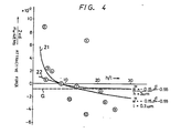
- Figure 4 is a graph in which the attractive force calculated by Equation (2) above, namely the force by which the bit is attracted to the high temperature side at the centre of the radiated beam, is plotted against the function or ratio h/l.
- reference numerals 1 to @ are respectively plots of examples of the samples 1 to 12 having the characteristics shown in Figure 3.
- the record medium having the sample number 8 is slightly displaced from the region which allows stable recording (hereinbelow referred to as the stable recording region).
- the sample 8 permits recording in practice, but the bit being recorded is sometimes displaced from the radiation position of the light beam. This coincides with the fact that the sample 8 is disposed on the border of the stable recording region. From the graph of Figure 4, it can be understood that the sample media having the sample numbers 9 to 12 are positioned far away from the stable recording region.
- the recording bit was always generated at a position distant from the radiation position of the light beam.
- the sample media 10 to 12 no recording was carried out at all. As a result, it was confirmed that whether stable recording at the centre of the light beam spot is possible or not depends on whether Equation (2) above can be satisfied.
- FIG. 5 is a graph in which, instead of the attractive forces as in the graph of Figure 4, the temperature coefficient of the collapse magnetic field H o is plotted against the function h/I.
- the above measurement was carried out on the basis of the fact that, when the collapse magnetic field H o is given by the relationship (see "Magnetic Bubble" page 28, issued by Maruzen Co., Ltd. in 1977).
- layers 2 of soft magnetic material having an easy axis of magnetisation normal to the surface of the layer 2 and made of (TmBi) 3 (FeGa) 5 0 12 , (TmBiSm) 3 (FeGa) 5 0 12 and (LuBiSm) 3 (FeGa) 5 0 12 were formed on a GGG substrate 1 of 500 microns thickness according to a liquid phase epitaxial growth technique to form a plurality of record media 3. Bit recording was carried out on the record media 3 and the bits thus formed were observed.
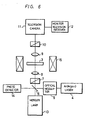
- laser light emitted from an Ar (argon) laser 4 is passed through an optical modulator 5 and thereby converted into the form of a pulsed light beam having a pulse width of 5.0 microseconds.
- the pulsed light beam is passed through a half mirror 6, a polariser 7 and a convergent lens 8 and then focussed on the magnetised layer 2 of the record medium 3 as a beam spot having a diameter of 1.0 microns.
- the intensity of the incident light beam on the record medium 3 was measured by a photo detector 14 and corrected. Then, whether or not the bit was formed or recorded on the magnetized layer 2 as described above was investigated as follows.
- Reference numeral 15 designates a bias magnetic field generating means by means of which the magnetised layer 2 of the record medium 3 is subjected to a magnetic field of 1/2 (H o +H 2 ), where H o is its collapse magnetic field and H 2 is its run-out magnetic field.
- H o is its collapse magnetic field
- H 2 is its run-out magnetic field.
- the values of the anisotropy magnetic field H k and the film thickness h of the magnetized film or layer 2 which allow recording with a recording power of lower than 10 mW lie within a region or range which is such that, in the coordinate system shown in Figure 7, in which the film thickness h is indicated on the abscissa thereof in micrometers and the anisotropy magnetic field H k is indicated on the ordinate thereof in Oersteds, the region is defined by connecting a point A (0.5, 0), a point B (0.5,3000), a point C (1.0, 3000), a point D (1.5,1800), a point E (3.0,800), a point F (6.0,400), a point G (6.0, 0) and the point A sequentially to one another by straight lines.
- the relationship between the anisotropy magnetic field H k and the film thickness h is selected so as to fall within the region which is formed by connecting the points A, B, C, D, E, F and A by straight lines.
- Example 2 the recording power Pw of the recording laser light for the anisotropy magnetic field H k which allows the formation of a bit was measured for a record medium having a thickness h of 2.3 ⁇ 0.2 microns. The measured results are shown in the graph of Figure 8.
- Record media 3 were formed according to the same method as that of Example 2. In this case, the recording laser light was radiated onto the magnetised layer 2 of each record medium 3 from the side of the substrate 1.
- the anisotropy magnetic field H k and the film thickness h of the magnetised layer 2 which allow recording with a recording power of lower than 10 mW lie within a region or range which, in the coordinate system as shown in Figure 9 in which the film thickness h is indicated on the abscissa thereof in micrometres and the anisotropy magnetic field H k on the ordinate thereof in Oersteds, is defined by joining a point A' (0.5, 0), a point B' (0.5,3000), a point C' (1.75,3000), a point D' (2.0, 1400), a point E' (4.0, 0) and the point A' sequentially to one another by straight lines.
- the relationship between the anisotropy magnetic field H k and the film thickness h is selected so as to fall within the region which is formed by connecting the points A', B', C', D' and A' to one another by straight lines.
- Example 3 the power Pw of the recording laser light for the anisotropy magnetic field H k which allows the formation of a bit was measured for a record medium 3 having a thickness h of 2.3 ⁇ 0.2 microns. The measured results are shown in the graph of Figure 10.
- Example 3 The reason why the recording power according to Example 3 is higher than that of Example 2 may be explained as follows.
- the magnetised layer 2 of the record medium 3 is irradiated with recording laser light from the side of the substrate 1, the magnetised film 2 is greatly heated at its position adjacentto the substrate 1 with the result that the heat is radiated through the substrate 1.
- the substrate 1 Even when the magnetised layer 2 of the record medium 3 is irradiated with the laser light from the side of the substrate 1, the substrate 1 has a high transmissivity to the Ar laser light so that the influence of the film thickness of the substrate 1 is negligible.
- Thermomagnetic recording methods embodying the present invention have the following advantages.
- the layer of soft magnetic material having an easy axis of magnetisation normal to the surface of the layer used in the present invention prefferably has a magnetic wall coercive force selected to have a certain constant value, for example lower than 2 to 3 Oe. Further, the layer can be used even if its crystallinity is not uniform. Thus, manufacture of the layer of soft magnetic material having an easy axis of magnetisation normal to the surface of the layer can be carried out more easily than in the prior art. As described above, the magnetic wall coercive force is small so that the recorded bit information can be erased by using a small magnetic field, thus bringing about a practical advantage.
- the form of the recorded bit is substantially perfectly cylindrical, there is an advantage that the bit information can be read out with excellent readout sensitivity.
- the diameter of the bit being recorded is not dependent on the output power of the input laser light, but can easily be controlled by changing the bias magnetic field, which feature is quite advantageous. Accordingiy, correction of the diameter of the bit after it has been recorded, which was impossible due to the large coercive force in the prior art, becomes possible, leading to a significant advantage in practice.
- the layer of soft magnetic material having an easy axis of magnetisation normal to the surface of the layer has no critical temperature such as a temperature compensation point near room temperature and, also, its Curie temperature is, for example, around approximately 200°C, the layer can stably maintain the information against changes of temperature over a wide range.
- the recording bit can stably be recorded at the centre of the spot of recording light with low power and, accordingly, recording can be carried out with high resolution, high sensitivity and high density.
Claims (3)


Applications Claiming Priority (4)
| Application Number | Priority Date | Filing Date | Title |
|---|---|---|---|
| JP167321/82 | 1982-09-25 | ||
| JP16732182A JPS5956202A (ja) | 1982-09-25 | 1982-09-25 | 熱磁気光記録方式 |
| JP5565183A JPS59180804A (ja) | 1983-03-31 | 1983-03-31 | 熱磁気光記録方法 |
| JP55651/83 | 1983-03-31 |
Publications (3)
| Publication Number | Publication Date |
|---|---|
| EP0104919A2 EP0104919A2 (fr) | 1984-04-04 |
| EP0104919A3 EP0104919A3 (en) | 1986-08-13 |
| EP0104919B1 true EP0104919B1 (fr) | 1990-01-31 |
Family
ID=26396551
Family Applications (1)
| Application Number | Title | Priority Date | Filing Date |
|---|---|---|---|
| EP19830305715 Expired EP0104919B1 (fr) | 1982-09-25 | 1983-09-26 | Méthodes d'enregistrement thermomagnétiques |
Country Status (3)
| Country | Link |
|---|---|
| EP (1) | EP0104919B1 (fr) |
| CA (1) | CA1212757A (fr) |
| DE (1) | DE3381184D1 (fr) |
Families Citing this family (1)
| Publication number | Priority date | Publication date | Assignee | Title |
|---|---|---|---|---|
| KR920005087A (ko) * | 1990-08-17 | 1992-03-28 | 야마무라 가쯔미 | 광자기 기록 및 재생 방법과 장치 |
Family Cites Families (2)
| Publication number | Priority date | Publication date | Assignee | Title |
|---|---|---|---|---|
| US3624622A (en) * | 1969-08-15 | 1971-11-30 | Honeywell Inc | Optical information storage system |
| NL160659C (nl) * | 1972-01-08 | 1979-11-15 | Philips Nv | Magneto-optische inrichting. |
-
1983
- 1983-09-21 CA CA000437179A patent/CA1212757A/fr not_active Expired
- 1983-09-26 EP EP19830305715 patent/EP0104919B1/fr not_active Expired
- 1983-09-26 DE DE8383305715T patent/DE3381184D1/de not_active Expired - Lifetime
Also Published As
| Publication number | Publication date |
|---|---|
| CA1212757A (fr) | 1986-10-14 |
| EP0104919A3 (en) | 1986-08-13 |
| EP0104919A2 (fr) | 1984-04-04 |
| DE3381184D1 (de) | 1990-03-08 |
Similar Documents
| Publication | Publication Date | Title |
|---|---|---|
| EP0128960B1 (fr) | Procede d'enregistrement/reproduction optique thermomagnetique | |
| Hansen et al. | Media for erasable magnetooptic recording | |
| Meiklejohn | Magnetooptics: A thermomagnetic recording technology | |
| JPS5916358B2 (ja) | 磁性層の製造方法 | |
| US4310899A (en) | Thermomagnetic record carrier | |
| US4581717A (en) | Thermomagnetic recording method | |
| US4586161A (en) | Permanent thermo-magnetic recording of binary digital information | |
| US5793711A (en) | Composite magneto-optic memory and media | |
| Suits et al. | Lorentz microscopy of micron‐sized laser‐written magnetic domains in TbFe | |
| EP0104919B1 (fr) | Méthodes d'enregistrement thermomagnétiques | |
| US4670316A (en) | Thermo-magnetic recording materials supporting small stable domains | |
| Togami et al. | Amorphous thin film disk for magneto-optical memory | |
| US4333991A (en) | Magnetic garnet film and manufacturing method therefor | |
| US5695863A (en) | Magneto-optical recording medium | |
| EP0129605A1 (fr) | Procede d'enregistrement optique thermomagnetique | |
| US4642795A (en) | Thermomagnetic recording system | |
| EP0125536A2 (fr) | Matériaux thermomagnétiques d'enregistrement supportant de petits domaines stables | |
| JPS5857646A (ja) | 垂直磁気記録・再生方法 | |
| KR960016360B1 (ko) | 광자기 기록방법 | |
| JPS5857645A (ja) | 垂直磁気記録用デイスク状媒体 | |
| JPH0614416B2 (ja) | 光磁気記録再生方法 | |
| EP0139021A1 (fr) | Procede d'enregistrement optique thermomagnetique | |
| KR100306975B1 (ko) | 준안정성합금을포함하는자성물질및그제조방법 | |
| JPH0440761B2 (fr) | ||
| Dekker et al. | Temperature dependence of the coercive force of MnBi films |
Legal Events
| Date | Code | Title | Description |
|---|---|---|---|
| PUAI | Public reference made under article 153(3) epc to a published international application that has entered the european phase |
Free format text: ORIGINAL CODE: 0009012 |
|
| AK | Designated contracting states |
Designated state(s): DE FR GB NL |
|
| PUAL | Search report despatched |
Free format text: ORIGINAL CODE: 0009013 |
|
| AK | Designated contracting states |
Kind code of ref document: A3 Designated state(s): DE FR GB NL |
|
| 17P | Request for examination filed |
Effective date: 19861219 |
|
| 17Q | First examination report despatched |
Effective date: 19880118 |
|
| GRAA | (expected) grant |
Free format text: ORIGINAL CODE: 0009210 |
|
| AK | Designated contracting states |
Kind code of ref document: B1 Designated state(s): DE FR GB NL |
|
| ET | Fr: translation filed | ||
| REF | Corresponds to: |
Ref document number: 3381184 Country of ref document: DE Date of ref document: 19900308 |
|
| PLBE | No opposition filed within time limit |
Free format text: ORIGINAL CODE: 0009261 |
|
| STAA | Information on the status of an ep patent application or granted ep patent |
Free format text: STATUS: NO OPPOSITION FILED WITHIN TIME LIMIT |
|
| 26N | No opposition filed | ||
| PGFP | Annual fee paid to national office [announced via postgrant information from national office to epo] |
Ref country code: GB Payment date: 19930924 Year of fee payment: 11 |
|
| PGFP | Annual fee paid to national office [announced via postgrant information from national office to epo] |
Ref country code: FR Payment date: 19930929 Year of fee payment: 11 |
|
| PGFP | Annual fee paid to national office [announced via postgrant information from national office to epo] |
Ref country code: NL Payment date: 19930930 Year of fee payment: 11 |
|
| PGFP | Annual fee paid to national office [announced via postgrant information from national office to epo] |
Ref country code: DE Payment date: 19931130 Year of fee payment: 11 |
|
| PG25 | Lapsed in a contracting state [announced via postgrant information from national office to epo] |
Ref country code: GB Effective date: 19940926 |
|
| PG25 | Lapsed in a contracting state [announced via postgrant information from national office to epo] |
Ref country code: NL Effective date: 19950401 |
|
| NLV4 | Nl: lapsed or anulled due to non-payment of the annual fee | ||
| GBPC | Gb: european patent ceased through non-payment of renewal fee |
Effective date: 19940926 |
|
| PG25 | Lapsed in a contracting state [announced via postgrant information from national office to epo] |
Ref country code: FR Effective date: 19950531 |
|
| PG25 | Lapsed in a contracting state [announced via postgrant information from national office to epo] |
Ref country code: DE Effective date: 19950601 |
|
| REG | Reference to a national code |
Ref country code: FR Ref legal event code: ST |